1
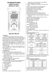
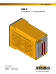
TABLE OF CONTENTS
MODEL “SBG”
PowerMaster
SINGLE ARM BARRIER GATE OPERATOR
Important Safety Information……………..…………….......3
System Designer Safety Instructions……...…….……..........4
Installer Safety Instructions …………...………………....….. 5
End User Safety Warnings …….….…………………….8-10
Installation & Setup Procedure
Before Installing Operator……..…………..……...………11
Installation of Cement Pad………......………..…………...12
Installation of Operator………………..……….…....13-14
Installation of Barrier Arm…...………………………..15-16
Electrical Connections………………..………………16-17
Clutch Adjustment……………..………….……………....18
Manual Operation………………….…..………….……....19
Limit Adjustment Procedure ………… …….…….…..19-20
Accessory Connections
Connection of a 2 Button……….………..…….……….…21
Connection of a 1 Button……….….……….……….…….21
Connection of a Radio………….….………………...….…22
Timer To Close……….…………………….…….….……23
External Timer Defeat Switch ………….…………………24
Auxiliary Limit Switch ……..…….…...………….………24
Master/Slave Operation………..……………..…..........25-27
Installation of Edge Sensor or Photo Eyes…….….…..…...28
Installation Manual
SINGLE ARM BARRIER GATE OPERATOR
UL 325 AND UL 991 LISTED
UL
Loop Detector Systems and Installation
Loop Layout Diagram….………….…..……….…….…….29
Standard Loop Layout Size Chart…………….....................30
Loop Installation………………………..……..………..….30
Cutting The Required Groove………...………...................31
Loop Detector Connections…………………….…………....32-34
Barcon Board Overview…………………………………...35
Wiring Diagram………………………………..…..............36
Notes/Maintenance Log…….………….………..................37
Warranty……………………………..…………………….38
R
2
IMPORTANT!
FOR BARRIER GATE OPERATING SYSTEMS
SAFETY IS EVERYONE’S BUSINESS
Automatic gate operators provide convenience and security to
users. However, because these machines can produce high
levels of force, it is important that all gate operator system
designers, installers, and end users be aware of the potential
hazards associated with improperly designed, installed, or
maintained systems. Keep in mind that the gate operator is a
component part of a total gate operating system.
The following information contains various safety precautions
and warnings for the system designer, installer and end user.
These instructions provide an overview of the importance of
safe design, installation, and use.
Warnings are identified with the ▲ symbol. This symbol will
identify some of the conditions that can result in serious injury or
death. Take time to carefully read and follow these precautions
and other important information provided to help ensure safe
system design, installation and use.
SYSTEM DESIGNER SAFETY INSTRUCTIONS
▲ 1. Familiarize yourself with the precautions and
warnings for the installer. Users are relying on your
design to provide a safe installation. The installation
should have an entrapment protection system
installed such as photoelectric sensors or an electric
edge.
▲ 2. When designing a system that will be entered from a
highway or main thoroughfare be sure the system is
placed far enough away from the road to eliminate
traffic backup. Distance from the road, size of the
gate, usage levels, and gate cycle/speed must be
considered to eliminate potential traffic hazards.
▲ 3. Design the gate system so a person cannot be
trapped between the arm and any other fixed
structure. All rigid objects must be at least 2 feet
from gate arm.
2
FEET
▲ WARNING: Gate operators are only one part of a
TOTAL GATE OPERATING SYSTEM.
It is the
responsibility of purchaser, designer, and installer to ensure
that the total system is safe for its intended use. All
secondary
entrapment
safety
devices
must
be
RECOGNIZED by U/L to ensure the safety of the complete
operating system.
3
4
INSTALLER SAFETY INSTRUCTIONS
BEFORE INSTALLATION
▲ 1. Check to see that the operator is proper for this
type and size of opening and its frequency of use.
If you are not sure, consult factory.
▲ 2. Check to see that there are no structures
adjacent to the area, which may pose a risk of
entrapment when gate is opening or closing.
DURING INSTALLATION
▲ 1. Be aware of all moving parts and avoid close
proximity to any pinch points.
▲ 2. Disconnect power at the control panel before making
any electric service connections.
Connection
location for controls and safety equipment can be
found on the wiring diagram, and in this manual.
▲ 3. Locate the controls at least 10 feet from the moving
gate so that the user can observe the gate operation,
but is not able to come in contact with the gate while
operating the controls.
▲ 3. Safety equipment such as electric edges or
photocell sensors must be installed to provide
personnel, equipment, and property protection.
For assistance in selecting the correct type of
safety equipment, consult the factory.
▲ 4. You must install a pushbutton control or key
switch to allow for normal operation of the gate if
the automatic controls do not work. Locate the
pushbutton or key switch and small warning
placard within sight of the gate in a secured area
at least 10 feet or more from the gate and fence
to keep users away from the moving gate and
fence.
▲ 5. Outdoor or easily accessed gate controls should
be of the security type to prohibit unauthorized
use.
10 FEET
5
6
AFTER INSTALLATION
END-USER SAFETY WARNINGS
▲ You are responsible for ensuring that the end
user understands the basic operations and
safety systems of the unit, including the proper
way to disengage and manually operate this
unit.
▲ Point out that the safety instructions in this
brochure are the responsibility of the end user,
and then LEAVE THIS BROCHURE WITH
THE END USER
Be sure you’ve been fully instructed on the sequence of
operation for your specific gate system(s). Keep the gate
properly maintained and have a qualified service person
make repairs.
▲ 1. Be sure the following safety instructions are
distributed to all persons authorized to use your
gate.
▲ 2. KEEP GATEWAY CLEAR AT ALL TIMES. Your
automatic gate is not for pedestrian use. No one
should ever cross the path of the moving gate.
7
8
▲ 3. DO NOT allow children to play near your gate, or
to operate the gate.
▲ 7. Be sure the gate arm DOES NOT come within 2
feet of any rigid object, therefore causing an entrapment
situation.
2
FEET
10 FEET
▲ 4. DO NOT operate your gate system unless you can
see it when the gate moves.
▲ 5. Be sure a pushbutton or key switch has been
installed for manual electric operation in the event
your radio or card does not work. Any mounted
control station should be located a minimum of 10
feet from the gate so the gate cannot be touched.
Any pushbutton located in a building should be
installed within sight of the gate.
▲ 6. DO NOT operate any controls without watching the
movement of the gate.
9
▲ 8. If your gate closes automatically, loop detectors
should be installed to detect the presence of a vehicle.
▲ 9. If a contact or non-contact safety system has been
installed check for proper operation at least once per
month. If these functions are observed to operate
improperly, discontinue use and have it serviced
immediately!
▲ 10. To ensure safe operation of this equipment, you
must read this safety manual and keep it for reference.
10
INSTALLATION INSTRUCTIONS
WARNING: DO NOT APPLY POWER UNTIL TOLD TO DO
SO! RISK OF ELECTRICAL SHOCK OR INJURY MAY
RESULT!
INSTALLATION OF CEMENT PAD
1. Install a mounting pad as shown below.
WARNING – Install operator mounting pad so moving
arm will always be at least 2 feet from any fixed object.
BEFORE INSTALLING OPERATOR
15-1/2"
IMPORTANT:
13-3/4"
(MOUNTING BOLTS)
1. Operator should always be mounted inside the gate.
2. All controls are to be mounted at least 10’ from the
gate arm.
16"
MIN.
2
FEET
8"
ELECTRICAL
ACCESS
9-3/4" (MOUNTING BOLTS)
ELECTRICAL
CONDUIT FOR
POWER SUPPLY
ELECTRICAL
ACCESS
24"
MIN.
1/2" ANCHOR BOLTS
GROUND LEVEL
4" MIN.
1-1/2" MIN.
2"
24" MIN.
10 FEET
ELECTRICAL
CONDUIT FOR
POWER SUPPLY
3. Allow at least 2 feet clearance from rigid objects to
gate arm.
11
Note: Let cement cure for two days before proceeding.
12
INSTALLATION OF OPERATOR
1. Remove top cover as follows:
•
•
•
Insert key provided and unlock top cover
lift cover from lock side and slide forward
lift off cover
3. Mount operator on pad so that mounting bolts locate
in operator base frame mounting holes and operator
is parallel to fence line. (See diagram below.)
4. Secure operator to cement using ½” flat washers, lock
washers and hex nuts as shown in diagram.
2. Remove side door of operator by reaching inside
operator and unscrewing retaining knob at top of
door. After removing retaining knob, push out top of
door and lift away from operator. See diagram below.
TOP COVER
EXTERIOR
COVER
KEY
1/2" HEX NUT (4)
1/2" LOCK WASHER (4)
SIDE COVER
RETAINING KNOB
1/2" FLAT WASHER (4)
DRIVE FRAME
ANGLE
SIDE DOOR
(4) 3/8" NUTS
CEMENT PAD
(4) 3/8"
LOCK WASHERS
(4) 3/8"
FLAT WASHERS
POWER HEAD
2" U-BOLTS
MOUNTING
BOLTS
NOTE: REDUCER AND MOTOR
NOT SHOWN FOR CLARITY.
2" PIPE
13
14
INSTALLATION OF BARRIER ARM
For 8’, 10’, or 12’ Arms
1. Install arm cap using (4) ½ x 1-1/2” long hex bolts,
lock washers and nuts as shown below. Do not
tighten until told to do so.
4. Mount counter weight on weight carrier bracket using
(2) ½” x 4” long hex bolts, lock washers and nuts as
shown in diagram. Be sure to use holes in weight
carrier bracket as shown in diagram for proper arm
balance.
OPERATOR
OUTPUT SHAFT
ARM MOUNTING
FLANGE
2. Insert large end of wood arm into arm cap until flush
with opposite edge of arm mounting flange.
3. Adjust arm to the desired horizontal position and
secure by tightening the 1/2” mounting hardware.
ARM
1/2" NUT (4)
OPERATOR
OUTPUT SHAFT
ARM MOUNTING
FLANGE
1/2" x 1-1/2"
HEX BOLT (4)
1/2" LOCK WASHER (4)
ARM
1/2" NUT (4)
1/2" LOCK WASHER (4)
1/2" x 1-1/2"
HEX BOLT (4)
1/2" NUT (2)
1/2" LOCK WASHER (2)
WEIGHT CARRIER
BRACKET
ARM CAP
1/2" X 4" LONG
HEX BOLT (2)
COUNTER
WEIGHT
NOTE: USE MOUNTING HOLES SHOWN ABOVE TO
MOUNT COUNTER WEIGHT FOR PROPER
BALANCE OF 14 FOOT OR 16 FOOT ARMS.
Electrical Connections
For 14’, and 16’ Arms
1. Install weight carrier bracket using (4) 1/2 x 1-1/2”
long hex bolts, lock washers and nuts as shown
below. Do not tighten until told to do so.
2. Insert large end of wood arm into weight carrier
bracket until it hits stop.
3. Adjust arm to the desired horizontal position and
secure by tightening the 1/2” mounting hardware.
15
WARNING- DO NOT APPLY POWER UNTIL TOLD TO DO
SO. RISK OF SHOCK OR INJURY MAY RESULT!
NOTE: Wiring to operator must use watertight materials in
accordance with local electric code.
See wire
gauge/distance charts for proper sizing.
Master/Slave
installations should have SEPARATE power supply wiring or
length of wire runs should be figured at half that shown on
the chart. This unit must be grounded in accordance with
N.E.C. and local codes.
16
Before connecting the operator, use a voltmeter to determine
that the electrical service is 115V. THIS OPERATOR
CANNOT BE CONNECTED TO 230 VOLTS. Damage will
result which is not covered under warranty.
CLUTCH ADJUSTMENT
Note: The clutch is set to the lightest setting at the
factory and will require adjustment for proper operation.
1. Remove top cover and side door.
Line
Voltage
HP
14
AWG
12
AWG
10
AWG
8
AWG
6
AWG
115
VAC
1/2
150’
250’
400’
500’
650’
Note: Before starting clutch adjustment, turn off power
switch on electrical panel, and set all four adjusting nuts
on clutch to the same position.
2. To tighten clutch, turn the four adjustment nuts, as shown
below, 1/4 turn at a time, in a clockwise direction.
1. Be sure power switches at source and in operator are OFF.
2. Connect incoming power lines and ground wire as shown
below.
Hot leg (black) to BLACK; Neutral (white) to White:
Ground to GREEN
OPERATOR
UTILITY BOX
BLK
BLK
WHT
WHT
GRN
GND
INSIDE UTILITY BOX,
CONNECT AS SHOWN
L O W V O L T A G E W IR E
G A U G E /D IS T A N C E C H A R T
24 AW G :
20 A W G :
18 AW G :
U p to 1 5 0 '
150' - 200'
2 5 0 ' - 1 ,5 0 0 '
INCOMING
POWER
115V - 1Ø
CLUTCH
ADJUSTMENT
NUTS
CLUTCH
ADJUSTMENT
NUTS
3. Replace side door to activate power interlock.
4. Turn on power switch on electrical panel.
5. Test barrier gate operation using the OPEN/CLOSE control
switch located on the electrical panel.
TIMER TO CLOSE
ON/OFF SWITCH
OPEN/CLOSE
CONTROL SWITCH
24 VOLT
OVERLOAD
110 VOLT
OVERLOAD
ON/OFF
POWER SWITCH
C o n tr o l w ir in g s h o u ld b e r u n a s tw is t e d
p a ir s . D O N O T r u n c o n t r o l w ir e s in t h e
s a m e c o n d u it a s p o w e r w ir e s . te le p h o n e
w ir e s , o r lo o p d e t e c t o r le a d s .
17
18
6. Observe clutch during the start of the OPEN cycle to
determine if clutch is slipping.
7. Repeat adjustment procedure, step #1 - #4 until there is no
clutch slippage when operator starts the OPEN cycle.
1. In order to achieve 90 degree arm movement from the
drive linkage, the limit cams must be set to obtain the
linkage positions shown below.
UPPER
CONTROL ARM
UPPER
CONTROL ARM
DRIVE
LINK
MANUAL OPERATION
1. Remove top cover, and side door.
DRIVE
LINK
▲ WARNING: TO AVOID INJURY, TURN OFF POWER
LOWER
CONTROL
ARM
SUPPLY SWITCH TO OPERATOR BEFORE MAKING ANY
ADJUSTMENTS.
2. Loosen adjustment nuts on drive clutch. Turn clutch to
raise or lower gate arm.
3. To return to powered operation re-adjust clutch as shown
in clutch adjustment section.
4. Turn on supply power to operator. Replace side door and
top cover.
LIMIT ADJUSTMENT PROCEDURE
LOWER
CONTROL
ARM
DRIVE LINKAGE IN
HORIZONTAL ARM POSITION
(DRIVE LINK AND LOWER
CONTROL ARM STRAIGHT
IN LINE)
DRIVE LINKAGE IN
VERTICAL ARM POSITION
(DRIVE LINK AND LOWER
CONTROL ARM FOLDED
TOGETHER IN LINE)
2. To set limit cam, loosen set screw and rotate to desired
position then tighten set screw.
ACTUATING
SCREW
WARNING: TURN OFF POWER SUPPLY BEFORE
MAKING ANY ADJUSTMENTS.
LIMIT SWITCH
NOTE: The drive linkage geometry prevents more than a 90 Degree
gate arm movement. (Horizontal to Vertical position.)
SET
SCREW
LIMIT CAMS
LIMIT CAM
SIDE VIEW
CLOSE
LIMIT SWITCH
VERTICAL
90o
OPEN
LIMIT SWITCH
AUX. LIMIT
SWITCH
HORIZONTAL
Note: Limits are set for 90 degree arm movement at
factory.
19
20
3. If a shorter stroke than 90 degrees is desired at either end,
limits may be reset to achieve this.
4. If the limit cams are adjusted correctly and the operator is
maintaining 90 degree rotation but the arm is not horizontal
in the down position; loosen the (4) mounting bolts, adjust
arm and retighten mounting bolts.
RADIO CONTROL INSTALLATION
1. Mount radio receiver in cabinet of operator. A mounting
bracket has been provided which may be used to directly
attach many commonly used radio receivers as shown
below.
CONNECTION OF A 2 BUTTON STATION
NOTE: All Control contacts must be NORMALLY OPEN.
•
•
•
Connect “COMMON” to Terminal #5.
Connect “OPEN” button to Terminal #6.
Connect “CLOSE” button to Terminal #7.
1
2
COMMON
OPEN
CLOSE
3
4
5
NOTE: For radios supplied with a coax cable and antenna, longer
radio range may be obtained by drilling a 3/8” diameter hole
through the operator cabinet and mounting antenna outside the
operator.
6
7
8
9
10
A Three or Four wire radio control receiver can be installed on this
operator. See the diagrams below for the correct connections to
match your installations equipment and desired functions.
CONNECTION OF A 1 BUTTON STATION
NOTE: If your radio’s connecting wires are not color coded as
shown, see the radio’s installation manual to determine which
wires are for the normally open contacts and which require the 24
VAC Power Supply.
NOTE: Control contacts must be NORMALLY OPEN.
1. Connect one wire from the single button control to terminal
#1 on the operator terminal strip.
2. Connect the second wire
from the single button
control to terminal #2 on
the operator terminal strip.
4 WIRE RADIO
CONNECTION
1
2
1
3
4
N.O.
CONTACT
4 WIRE
RADIO
24 VAC
21
3 WIRE RADIO
CONNECTION
GY
GY
BK
R
2
3
1
4
R1
N.O.
CONTACT
3 WIRE
RADIO
R2
R3
POWER
R4
22
2
3
4
TIMER TO CLOSE OPTION
The operator is equipped with a timer to close option for use with
other control devices such as a radio control, or card key control.
EXTERNAL TIMER DEFEAT SWITCH CONNECTION
1. Connect the two wires from the normally open terminal of
the external ”Timer Defeat Switch” to terminals #9 and #10
as shown in diagram.
TIMER TO CLOSE
ON/OFF SWITCH
TIMER TO CLOSE
ON/OFF SWITCH
OPEN/CLOSE
CONTROL SWITCH
24 VOLT
OVERLOAD
OPEN/CLOSE
CONTROL SWITCH
24 VOLT
OVERLOAD
110 VOLT
OVERLOAD
7
110 VOLT
OVERLOAD
ON/OFF
POWER SWITCH
ON/OFF
POWER SWITCH
8
ON
9
OFF
10
10
EXTERNAL TIMER
DEFEAT SWITCH
12
NOTE:
TIMER IS TURNED OFF WHEN SWITCH IS
CLOSED BETWEEN TERMINALS #9 AND #10.
The AUTO RECLOSE TIMER adjustment screw is located on the
printed circuit board. The operator is shipped from the factory with
this timer preset to the “MIN.” position; fully counter clockwise, and
the “TIMER TO CLOSE” toggle switch in the “OFF” position. As
the timer adjustment screw is rotated clockwise, the closing of the
gate can be delayed from 1 second to 10 seconds.
1. To activate the AUTO-RECLOSE TIMER, put the “TIMER
TO CLOSE” toggle switch located on the electrical control
panel, to the “ON” position.
2. The desired length of time before closing may be selected by
turning the timer adjustment on the printed circuit board as
shown below. A timing option between 0 – 10 seconds is
available.
2. Move the “Timer To Close” switch on the operator control
panel to the “ON” position.
AUXILIARY LIMIT SWITCH
There is an auxiliary limit switch available which provides a
normally open and normally closed set of contacts for use with
additional equipment. It can be connected through terminals #12,
#13, and #14 on the terminal strip as shown in the diagram, and
can be set to activate at any point during gate travel. Adjustment
is accomplished by rotating the Aux. Limit cam to the desired
position and securing that location with the set screw in the cam.
AUX. LIMIT CAM
TIMER TO CLOSE
ADJUSTMENT
MIN.
CLOSE
LIMIT SWITCH
MAX.
OPEN
M1
M2
W2 W1
23
12
OPEN
LIMIT SWITCH
L1
1
2
3
4
5
6
7
8
9
10
11
12
0-10 SEC.
L2
CLOSE
AUX. LIMIT
SWITCH
NC
13
NO
14
AUX. LIMIT
SWITCH
NOTE: This option is not available when a MASTER/SLAVE
installation is connected to a radio control.
24
MASTER - SLAVE OPERATION
CONNECTION FOR A 1 BUTTON STATION
W/ MASTER-SLAVE OPTION
CONNECTIONS FOR MASTER/SLAVE OPERATION
WHEN USING ONE BUTTON CONTROL
REMOVE AND ISOLATE RED WIRE TO
TERMINAL #2 IN MASTER ONLY
NOTE:
QUICK CLOSE FUNCTION CAN NOT BE USED WHEN
MASTER/SLAVE OPTION IS CONNECTED.
OPEN
M1
L2
CLOSE
M2
L1
1
W2 W1
1
2
3
4
5
6
7
8
9
10
11
12
W2 W1
MASTER CONTROL BOARD
MASTER
TERMINAL
STRIP
NOTE:
CONNECT ALL CONTROLS TO
MASTER TERMINAL STRIP.
RED
2
1
1
2
2
3
3
3
4
4
4
5
5
6
6
7
7
8
8
9
9
10
10
12
NC
13
NO
14
AUX. LIMIT
SWITCH
5
SLAVE
TERMINAL
STRIP
MASTER
TERMINAL
STRIP
NOTE:
CONNECT ALL CONTROLS TO
MASTER TERMINAL STRIP.
10
NOTE:
USE 22 GA. WIRE MINMUM
FOR CONNECTIONS
BETWEEN OPERATORS.
10
12
13
14
TURN OFF TIMER
TO CLOSE IN
SLAVE UNIT
6
7
8
9
10
ADD THESE THREE
JUMPERS WHEN
USING ONE BUTTON
CONTROL STATION
10
CLOSE
LIMIT SWITCH
12
OPEN
LIMIT SWITCH
AUX. LIMIT
SWITCH
NC
13
NO
14
1.
Remove red wire from terminal #2 on Master terminal strip.
2.
1. Connect terminal #5 on Master terminal strip to terminal
“W1” on Master Control Board.
Connect 1-Button Control to Master terminal strip terminals
#1 & #2 as shown in diagram.
3.
2. Connect terminal “W2” on Master Control Board to terminal
#7 on Slave terminal strip.
Insert a jumper between terminal #2 and terminal #12 on
Master terminal strip.
4.
Insert a jumper between terminal #6 and terminal #13 on
Master terminal strip.
5.
Insert a jumper between terminal #7 and terminal #14 on
Master terminal strip.
Adjust the auxiliary limit switch cam so the “Aux. Limit”
switch activates just before the “OPEN” limit switch.
CLOSE
LIMIT SWITCH
OPEN
LIMIT SWITCH
AUX. LIMIT
SWITCH
3. Connect terminal #5 on Master terminal strip to terminal #5
on Slave terminal strip.
4. Connect terminal #6 on master terminal strip to terminal #6
on Slave terminal strip.
5. Connect terminal #8 on Master terminal strip to terminal #8
on Slave terminal strip.
6.
NOTE: This adjustment is preset at the factory and should
not need adjustment unless disturbed.
6. Turn off “Timer To Close” switch on Slave control panel.
25
26
CONNECTION FOR RADIO CONTROL
W/ MASTER-SLAVE OPTION
WHEN USING RADIO REMOVE
AND ISOLATE RED WIRE TO
TERMINAL #2 IN MASTER ONLY
INSTALLATION OF EDGE SENSOR OR PHOTOEYES
REFLECTOR
RADIO
RECEIVER
1
RED
2
3
4
24 VAC
EDGE SENSOR
5
MASTER
TERMINAL
STRIP
NOTE:
CONNECT ALL CONTROLS TO
MASTER TERMINAL STRIP.
6
7
8
9
ADD THESE THREE
JUMPERS WHEN
USING RADIO
10
10
CLOSE
LIMIT SWITCH
12
OPEN
LIMIT SWITCH
AUX. LIMIT
SWITCH
NC
13
NO
14
PHOTOELECTRIC CELL
AUX. LIMIT
SWITCH
1.
Remove red wire from terminal #2 on Master terminal strip.
2.
Connect radio to Master terminal strip as shown in
diagram: Open contacts from radio to terminals #1 and #2,
24VAC power to radio from terminals #3 & #4.
3.
Insert a jumper between terminal #2 and terminal #12 on
Master terminal strip.
4.
Insert a jumper between terminal #6 and terminal #13 on
Master terminal strip.
5.
Insert a jumper between terminal #7 and terminal #14 on
Master terminal strip.
6. Adjust the auxiliary limit switch cam so the “Aux” limit
switch activates just before the “OPEN” limit switch.
This adjustment is preset at the factory but may need
a minor adjustment for certain radios.
27
NOTE: 24 VAC power is available between terminals 3 &
4 for devices such as photo eyes, wireless edges, etc. All
safety device contacts must be NORMALLY OPEN.
1. Install edge sensor or photoelectric eye system as
shown. Photocells should be installed at least 10”
above the ground.
▲ NOTE: All hard wiring to safety edges must be
installed so there is no threat of mechanical damage
to wiring between components, when the gate is
moving.
▲ NOTE: A separate pedestrian gate must be installed if
there is no other entry access but the vehicular gate.
2. Electrically connect sensing system to operator terminal
strip as shown below.
28
8
FROM EDGE SENSOR OR
PHOTOELECTRIC EYE
9
10
usually used for one way traffic. It can only be activated
when there is no input from an “Open” or “Close Safety”
device . Once activated it will disable any “Close Safety”
device and can only be overridden by an “Open” input.
Therefore, this option should only be used in secure
applications and a close warning device should be
connected.
LOOP DETECTOR SYSTEMS AND INSTALLATION
LOOP INSTALLATION
4'
4'
4'
4'
4'
4'
1. Layout the desired loop locations
per the diagram. The standard size
chart at right will give an
approximate length of wire required
for various loop dimensions and
number of turns required.
8'
4'
3 / 1 6 " T O 1 /4 "
SAW SLO T
RO AD SURFACE
M IN 1 "
SEALANT
L O O P W IR E S
1. The EXIT LOOP provides a signal to open the gate when a
vehicle enters the loop zone.
2. The REVERSING LOOP protects a vehicle in the loop
zone from being contacted with the gate by overriding any
close signal while the gate is open, and by reversing the
gate if closing, unless the “Quick Close” Anti-Tailgate loop
has been installed.
3. The CLOSE LOOP provides a signal to close the gate
when a vehicle exits the loop.
CAUTION: The Loop wires and
Lead-in
wires
must
be
a
continuous piece of wire without
splices. The chart at right shows
the amount of wire required for
the loop sizes shown. The length
of the lead-in should be added to
the loop wire length to get the
required amount of wire for the
application.
Only
use
wire
intended
for
this
type
of
application.
(Type
XHHW
insulation 16AWG)
NOTE: Buried steel from drains or
other systems may affect functioning
of the loop system. Check with the
factory for advice on any special
installations.
(1-800-243-4476).
4. The QUICK CLOSE LOOP (Anti-Tailgate feature) is
29
30
STANDARD LOOP LAYOUTS
For 36” High Detection
Loop Wire
(See Chart)
7. An accessory mounting bracket has been provided in
the operator for mounting two loop detectors. (See
diagram)
Lead In Wire
(Twisted At 6
Turns Per Foot)
1/2" Conduit
Conduit Cut
3/16" To 1/4"
8. Connect loop detector to the control board and the wire
loop as shown in the following diagrams.
1" To 2"
1" To 2"
2. Cut the required groove as shown in the diagram above
at the locations laid out in Step #1.
3. Leave enough wire for the LEAD IN, and insert the
specified number of turns of wire into the cut grooves.
(See chart on previous page.)
CAUTION: Be careful not to damage the wire insulation
during installation.
Note: The following diagrams show single loop
connections. For multiple loop connections consult the
loop detector’s instruction manual, or call the
PowerMaster Technical line at 1-800-243-4476.
1. The EXIT LOOP provides a signal to open the gate when a
vehicle enters the loop zone.
EXIT LOOP CONNECTION
V
OR
R
P
4. After completing the required number of loop turns,
twist the ends together at the rate of 6 turns per foot to
form the LEAD-IN.
1
2
3
4
5
6
7
5. Seal the LEAD-IN wire in the conduit to prevent
moisture seepage into the conduit.
6. Fill over the loop wires in the groove with a
recommended loop sealant. Contact your distributor for
available sealants.
31
Not Used
BL
BK
GR
WH
BR
GY
TO DRIVEWAY
LOOP
NOTE: TWIST LEADS APPOX.
6 TURNS PER FOOT.
Y
32
2. The REVERSING LOOP protects a vehicle in the loop
zone from being contacted with the gate by over riding any
close signal while the gate is open, and by reversing the gate if
closing.
QUICK CLOSE LOOP CONNECTION
V
BL
Y
P
Not Used
REVERSING LOOP CONNECTION
1
2
3
4
5
6
7
8
9
10
11 12
V
OR
R
P
1
2
3
4
5
6
7
8
9
10
Not Used
OR
TO
BR
DRIVEWAY
GY LOOP
R
11
GR
WH
NOTE: TWIST LEADS APPOX.
6 TURNS PER FOOT.
BK
BL
Y
BR
GY
GR
BK
TO
DRIVEWAY
LOOP
NOTE: TWIST LEADS APPOX.
6 TURNS PER FOOT.
WH
3. The CLOSE LOOP provides a signal to close the gate when
a vehicle exits the loop.
CLOSE WARNING CONNECTION
L2
OPEN
CLOSE
M1
M2
L1
W2 W1
CLOSE LOOP CONNECTION
WARNING LOOP DETECTOR MUST BE PROGRAMMED TO
ACTIVATE OPERATOR WHEN VEHICLE LEAVES LOOP.
(SEE LOOP DETECTOR INSTRUCTIONS OR CALL FACTORY TECHNICAL
HELP AT 1-800-243-4476)
1
2
3
4
5
6
7
8
W2 W1
V
Not Used
1
2
3
4
5
6
7
8
9
10
11
12
BL
Y
P
9
OR
R
GR
WH
BR
GY
TO
DRIVEWAY
LOOP
NOTE: TWIST LEADS APPOX.
6 TURNS PER FOOT.
BK
4. The QUICK CLOSE LOOP (Anti-Tailgate feature) is usually
used for one way traffic. It can only be activated when there is
no input from an “Open” or “Close Safety” device. Once
activated it will disable any “Close Safety” device and can only
be over ridden by an “Open” input. Therefore, this option
should only be used in secure applications and a close
warning device should be connected to terminals W1 and W2.
( See “Close Warning Connection Diagram”)
33
34
5 AMP, 250V NORMALLY OPEN
CONTACTS FOR USE WITH
WARNING DEVICES
BARCON CONTROL BOARD QUICK OVERVIEW
CLOSE
OPEN
M2
M1
L2
L1
"TIMER TO CLOSE"
ADJUSTMENT (0 TO 10 SEC.).
W2 W1
"CLOSE TIMER INHIBIT"
WHEN LIT INDICATES
THAT THE TIMER TO
CLOSE IS SWITCHED OFF.
NORMALLY OPEN
"CLOSE WARNING"
RELAY CONTACTS
(RATING 5A, 250 VAC).
NOTE:
CONTACTS CLOSE
WHEN EVER GATE IS
CLOSING.
WHEN LIT:
INDICATES (24 VAC) IS PRESENT.
CTI
"ACTIVE CLOSE SAFETY" WHEN LIT:
INDICATES THAT A CLOSE
SAFETY DEVICE IS ACTIVATED
AND ANY CLOSE CONTROLS
HAVE BEEN DISABLED.
POWER
ACS
CLO
OPEN
RC
WHEN LIT:
INDICATES A "CLOSE"
INPUT IS ACTIVE.
WHEN LIT:
INDICATES THAT A
"RADIO" OR SINGLE
BUTTON IS ACTIVE.
1 2 3 4 5 6 7 8 9 10 11 12
WHEN LIT:
INDICATES A "OPEN"
INPUT IS ACTIVE.
35
QC
WHEN LIT:
INDICATES THAT A
"QUICK CLOSE"
INPUT IS ACTIVE.
36
Operator Information
The end user should retain this information for their
records to obtain service for their unit.
Model SBG
Location Installed:
Date Installed____________ Address_____________________
Serial # ________________ Address _____________________
Address _____________________
Installer’s Information
Company Name _____________________________________
Company Address ___________________________________
Company Address ___________________________________
Company Address ___________________________________
Company Telephone # ________________________________
Company Contact ____________________________________
NOTES
______________________________________________
______________________________________________
______________________________________________
______________________________________________
______________________________________________
______________________________________________
______________________________________________
______________________________________________
______________________________________________
______________________________________________
______________________________________________
______________________________________________
______________________________________________
37
PowerMaster
Limited 5 Year Warranty
PowerMaster warrants all gate operators to be free of defects in
materials and workmanship for a period of Five (5) years from date
of purchase. If any part is found to be defective during this period,
new parts will be furnished free of charge. Failure of this product
due to misuse, improper installation, alterations, vandalism, or
lack of maintenance are not covered under this warranty, and voids
any other implied warranties herein.
PowerMaster is not responsible for any labor charges incurred in
connection with the installation of warranted parts.
In order to activate this warranty, the registration form below
MUST be completed and returned within THIRTY
CALENDER DAYS FROM DATE OF PURCHASE VIA
CERTIFIED MAIL, FAX (631-951-3934) or email to
[email protected]. If registration is not
activated, a one year warranty will apply.
Registration Information
Model SBG
Location Installed:
Date Installed____________ Address ______________________
Serial # ________________ Address ______________________
Address _______________________
Installer’s Information
Company Name ______________________________________
Company Address ____________________________________
Company Address ____________________________________
Company Address ____________________________________
Company Telephone # _________________________________
Company Contact _____________________________________
38
39
40