1
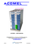
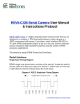
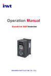
Technical description
Edition JAN12/2007
File: ACO5_Profibus_prod_spec_gb
Communication profile
PROFIBUS DP for the
Product Line ACO5000
PRELIMINARY
DANAHER MOTION S.A. La Pierreire 2, CH-1029 Villars-Ste-Croix
Telephone +41-21-631 33 33, Telefax +41-21-636 05 09
E-mail: [email protected]
www.danaher-motion.ch
Printed / Converted to PDF: 12.01.2007 / 10:01:21 /HJU
DANAHER MOTION SA
Edition
March 14, 2005
June 10, 2005
June 29, 2006
January 12, 2007
Comments
First PRELIMINARY version
Registration of GSD file, clarification of transmit and receiver buffer
• Completion of chap. 3.5.2.12 &13
• Correction of chap. 4.2.1 and completion of chap. 4.2.3
• Added PNU 1100.
• Added PNU 1301
• Added PNU 1302
Acknowledgements
Danaher Motion SA has made every effort to supply Trademark Company names, products and
services mentioned in this document. All brand names and product names are trademarks or
registered trademarks of the proprietors of the respective titles.
All rights reserved. This document remains the intellectual property of Danaher Motion SA, who
also owns the exclusive copyright.
No part of this document may be reproduced, transmitted, transcribed, stored in a retrieval system,
in any form or by any means, electronic, mechanical, optical, manual or otherwise, without
permission in writing form to copyright of Danaher Motion SA.
Pass on to third parties is only allowed if the explicit permission of Danaher Motion SA is obtained
beforehand.
Danaher Motion SA declines all claims for damages which arise from the application of
information that may be wrong or inadequate or missing in this document.
Danaher Motion SA reserves the right to change this document completely or partially without
prior notice.
Page 2 of 32 (PRELIMINARY)
PROFIBUS DP – product line ACO5000
DANAHER MOTION SA
TABLE OF CONTENT
1.
GENERAL ..................................................................................................................................... 5
1.1.
1.2.
1.3.
2.
INSTALLATION / SETUP ............................................................................................................. 6
2.1.
2.2.
3.
ABOUT THIS MANUAL .................................................................................................................... 5
REPRESENTATION CONVENTION .................................................................................................... 5
SAFETY INSTRUCTIONS ................................................................................................................. 5
HARD- AND SOFTWARE INSTALLATION ........................................................................................... 6
PARAMETERIZATION OF THE MASTER-INTERFACE MODULE .............................................................. 6
INTRODUCTION: PROFIDRIVE................................................................................................... 7
3.1. GENERAL DESCRIPTION ................................................................................................................ 7
3.1.1. Parameter / Service Channel (PKW channel)................................................................. 8
3.1.2. Process Data Channel (PZD channel) ............................................................................ 8
3.2. PARAMETER / SERVICE CHANNEL (PKW)...................................................................................... 8
3.2.1. Parameter ID (PKE) ........................................................................................................... 8
3.2.1.1.
Interpretation of the response IDs ............................................................................... 9
3.2.1.2.
Profile specific error numbers with response ID 7....................................................... 9
3.2.2. Subindex (IND) ................................................................................................................ 10
3.2.3. Parameter value (PWE) .................................................................................................. 10
3.3. THE PROCESS DATA CHANNEL (PZD)......................................................................................... 10
3.4. READ / WRITE AN AMPLIFIER PARAMETER ..................................................................................... 11
3.5. SUMMARY OF THE PARAMETER NUMBERS .................................................................................... 11
3.5.1. Profile parameters .......................................................................................................... 12
3.5.1.1.
PNU 904 / 911: PPO - type ....................................................................................... 12
3.5.1.2.
PNU 918: PROFIBUS – node address...................................................................... 12
3.5.1.3.
PNU 930: Selector for operating modes.................................................................... 12
3.5.1.4.
PNU 963: BAUDRATE .............................................................................................. 13
3.5.1.5.
PNU 965: PROFIDRIVE profile number.................................................................... 13
3.5.2. Manufacturer specific parameters (ACO5000) ............................................................ 13
3.5.2.1.
PNU 1000: Device name ........................................................................................... 14
3.5.2.2.
PNU 1001: Manufacturer-specific error..................................................................... 14
3.5.2.3.
PNU 1002: Manufacturer-specific status................................................................... 15
3.5.2.4.
PNU 1003 Embedded software version. ................................................................... 15
3.5.2.5.
PNU 1010 Delivery dates of drive. ............................................................................ 15
3.5.2.6.
PNU 1011 Serial number of drive.............................................................................. 15
3.5.2.7.
PNU 1012 Running time............................................................................................ 16
3.5.2.8.
PNU 1013 Time during which power is applied. ....................................................... 16
3.5.2.9.
PNU 1050 Value of actual motor current................................................................... 16
3.5.2.10. PNU 1052 Mirror of analog output “SAN1”. .............................................................. 16
3.5.2.11. PNU 1053 Mirror of analog output “SAN2”. .............................................................. 16
3.5.2.12. PNU 1054 Meaning of displayed value on “SAN1”. .................................................. 16
3.5.2.13. PNU 1055 Meaning of displayed value on “SAN2”. .................................................. 16
3.5.2.14. PNU 1056 Value of actual motor power.................................................................... 17
3.5.2.15. PNU 1057 Value of actual motor voltage .................................................................. 17
3.5.2.16. PNU 1058 Value of actual main voltage ................................................................... 17
3.5.2.17. PNU 1059 Value of actual internal DC power voltage .............................................. 17
3.5.2.18. PNU 1060 Value of actual motor temperature (PTC style) ....................................... 17
3.5.2.19. PNU 1061 Value of actual drive temperature ........................................................... 17
3.5.2.20. PNU 1062 Value of actual motor temperature (KTY style) ....................................... 17
3.5.2.21. PNU 1070 Value of “MCM ABS 0” ............................................................................ 17
3.5.2.22. PNU 1071 Value of “MCM ABS 1” ............................................................................ 17
3.5.2.23. PNU 1072 Value of “MCM ABS 2” ............................................................................ 17
3.5.2.24. PNU 1073 Value of “MCM ABS 3” ............................................................................ 17
3.5.2.25. PNU 1080 Value of “MCM SH 0” .............................................................................. 18
3.5.2.26. PNU 1081 Value of “MCM SH 1” .............................................................................. 18
PROFIBUS DP – product line ACO5000 (PRELIMINARY)
Page 3 of 32
DANAHER MOTION SA
3.5.2.27.
3.5.2.28.
3.5.2.29.
3.5.2.30.
3.5.2.31.
3.5.2.32.
3.5.2.33.
3.5.2.34.
3.5.2.35.
3.5.2.36.
3.5.2.37.
3.5.2.38.
3.5.2.39.
3.5.2.40.
3.5.2.41.
3.5.2.42.
3.5.2.43.
3.5.2.44.
4.
PNU 1082 Value of “MCM SH 2” .............................................................................. 18
PNU 1083 Value of “MCM SH 3” .............................................................................. 18
PNU 1090 Value of “MCM DTO 0”............................................................................ 18
PNU 1091 Value of “MCM DTO 1”............................................................................ 18
PNU 1092 Value of “MCM DTO 2”............................................................................ 18
PNU 1093 Value of “MCM DTO 3”............................................................................ 18
PNU 1094 Selection of type of “MCM” ...................................................................... 18
PNU 1095 Selection of level of “MCM” ..................................................................... 18
PNU 1100 Value of active partition ........................................................................... 20
PNU 1200 Value of dynamic acceleration time......................................................... 20
PNU 1201 Value of dynamic deceleration time ........................................................ 20
PNU 1202 Value of low frequency stabilization “SBF”.............................................. 20
PNU 1204 Value of DC brake current ....................................................................... 20
PNU 1205 Value of time of DC brake current ........................................................... 20
PNU 1206 Value of permanent DC brake current..................................................... 20
PNU 1300 Value of set speed................................................................................... 20
PNU 1301 Value of maximum speed of partition ...................................................... 20
PNU 1302 Value of minimum speed of partition ....................................................... 20
PROCESS DATA CHANNEL ..................................................................................................... 21
4.1. INSTRUMENT CONTROL ............................................................................................................... 21
4.1.1. Control word (STW) ........................................................................................................ 22
4.1.2. Status word (ZSW).......................................................................................................... 23
4.2. OPERATING MODES .................................................................................................................... 25
4.2.1. Digital speed (operating mode 1) .................................................................................. 25
4.2.2. Analog speed (operation mode –1)............................................................................... 25
4.2.3. Example returned status................................................................................................ 25
5.
SAMPLE TELEGRAMS AND EXAMPLES ................................................................................ 30
5.1.
5.2.
5.3.
ZERO TELEGRAM ........................................................................................................................ 30
SETTING THE OPERATING MODE .................................................................................................. 30
ENABLE THE DRIVE................................................................................................................... 31
Page 4 of 32 (PRELIMINARY)
PROFIBUS DP – product line ACO5000
DANAHER MOTION SA
1.
GENERAL
1.1.
About this manual
This operating manual applies to the ACO5000 product line family. It describes the connections and
basic functions of the standard models.
For more general information about PROFIBUS, please visit the following web page www.profibus.com.
1.2.
Representation convention
Unless otherwise noted all data represented in this manual are in the so called “Little- Endian”
representation. See table 1 for in dissociable data bytes.
Along this manual, the word motor is used for both motor and spindle.
1.3.
Safety instructions
See ACO5000 User manual.
Never use ACO5000 Windows setup program when the ACO5000 is running with a PROFIBUS master.
This will cause unexpected result and/or crash of PROFIBUS functionality!
PROFIBUS DP – product line ACO5000 (PRELIMINARY)
Page 5 of 32
DANAHER MOTION SA
2.
INSTALLATION / SETUP
2.1.
Hard- and Software installation
2.2.
Parameterization of the master-interface module
The characteristic communication features of a PROFIBUS device are defined in the form of an
electronic device data sheet or device description file (GSD, in german "Geräte-Stamm-Datei").
Figure 1
GSD files expand open communication up to operator control level. GSD files can be loaded during
configuration. This means that integration of devices from different manufacturers into the PROFIBUS
system is simple and user-friendly.
Use our registered "ACO50992.GSD" file by PROFIBUS Nuetzerorganisation for this configuration.
Page 6 of 32 (PRELIMINARY)
PROFIBUS DP – product line ACO5000
DANAHER MOTION SA
3.
INTRODUCTION: PROFIDRIVE
3.1.
General Description
The PROFIBUS-profile “PROFIdrive” includes the following parameter process-data objects (PPO):
BYTE
1
2
3
4
5
6
7
PKW
8
9
10
11
12
13
14
PZD3
15
PZD1
PZD2
STW
HSW(*)
(*) not used
16
PZD4
17
18
PZD5
19
20
PZD6
PKE
IND
PWE
ZSW
HIW(*)
PZD34
PZD56
Data
block 1
Data
block 2
Data block 3
Data
block 4
Data
block 5
Data block 6
Data block 7
21
22
PZD7
23
24
PZD8
25
26
27
PZD9
28
PZD10
ABBREVIATIONS
Typ 1 : Octet-String 12
PKW
PKE
IND
PWE
Typ 2 : Octet-String 20 (Used by ACO5000)
STW
HSW
ZSW
HIW
PZD
Typ 3 : Octet-String 4
Parameter ID value
Parameter ID (1st and 2nd octet)
Index with PPO (3rd octet),
4th octet is reserved
Parameter value (5th to 8th
octet)
Main control word
Secondary control word
Main status word
Secondary control word
Process data
Typ 4 : Octet-String 12
Typ 5 : Octet-String 28
Table 1.
ACO5000 only uses the PPO-type 2 (with 4 words PKW-section and 6 words PZD-section).The PKWsection is used mainly for the transmission of parameters for the drive, the PZD-section is used
principally for handling motion functions. Furthermore, it means that the total amount of buffer size
needed for a write and read is equal to 2 "Octet-String 20" (40 octets, 20 for write and read).
The table 2 shows the buffer place requested for a write and read and meaning
Byte
1
2
3
4
5
6
7
Write from master to ACO5000
PKE
IND
PWE
Byte
21 22 23 24 25 26 27
Read from ACO5000 into master
PKE
IND
PWE
8
9
10
STW
28
29
ZSW
30
11
12
13
14
HSW
PZD34
31
33
32
HIW
Table 2.
PROFIBUS DP – product line ACO5000 (PRELIMINARY)
34
PZD34
15
16
17
18
19
20
39
40
PZD56
35
36
37
38
PZD56
Page 7 of 32
DANAHER MOTION SA
The instrument profile can be divided into two sections or data channels:
1. PKW-section (4 words)
2. PZD-section (6 words)
3.1.1.
Parameter / Service Channel (PKW channel)
The PKW data channel can also be called the service channel. The service channel only uses
confirmed communication services, and is used by ACO5000 as a parameter channel. This channel
has no real-time capability.
3.1.2.
Process Data Channel (PZD channel)
The PZD data channel can also be termed the process data channel. The process data channel uses
unconfirmed communication services. The response of the servo amplifier to an unconfirmed service
can only be seen in the reaction of the instrument (status word, actual values).This channel has realtime capability.
3.2.
Parameter / Service Channel (PKW)
The service channel PKW is subdivided in 3 categories that have the following meaning:
PKE (Parameter ID (1st and 2nd byte)
For meaning see "3.2.1."
3.2.1.
PKW (Parameter ID value)
IND (Index according PPO)
For meaning see "3.2.2."
Table 3.
Parameter ID (PKE)
Byte 1
15
14
PWE (Parameter value)
For meaning see "3.2.3."
13
12
11
ABBREVIATIONS
Byte 2
10
9
8
7
6
5
4
3
2
1
0
AK
SPM
PNU
AK
SPM
task / response ID
Toggle-Bit for spontaneous message
(not implemented at present)
Parameter number
PNU
Table 4.
Bold lines in the table are valid for the ACO5000
Task ID
0
1
2
3
4
5
6
7
8
9
10 – 15
Master —> Slave
Slave —> Master
Function
Response ID positive Response ID negative
no task
0
0
request parameter value
1,2
7
alter parameter value [W]
1
7/8
alter parameter value [DW]
2
7/8
request description element
3
7
alter description element
3
7/8
request parameter value [A]
4,5
7
alter parameter value [A/W]
4
7/8
alter parameter value
5
7/8
request number of array elements
6
7
Reserved
Table 5.
Page 8 of 32 (PRELIMINARY)
PROFIBUS DP – product line ACO5000
DANAHER MOTION SA
3.2.1.1. Interpretation of the response IDs
Response ID Interpretation
0
no task
1
transmit parameter value
2
transmit parameter value
3
transmit description element
4
transmit parameter value
5
transmit parameter value
6
transmit number of array elements
7
task is not possible (with error no.)
8
no operating authority for PKW interface
9
spontaneous message [W]
10
spontaneous message [DW]
11
spontaneous message [A/W]
12
spontaneous message [A/DW]
Table 6.
Abbreviations in the tables:
A: Array
W: Word
DW: Double-word
3.2.1.2. Profile specific error numbers with response ID 7
Error no.
0
1
2
3
4
5
6
7
8
9
10
11
12
13
14
15
16
17
18
19-100
101
102
103
104
105
106
107
108
Description
illegal PNU
parameter value cannot be changed
Lower or upper limit violated
Erroneous sub-index
no array
Incorrect data type
setting not allowed (can only be reset)
Descriptive element cannot be changed
PPO-write, requested in IR, not available
descriptive data not available
access group incorrect
No parameter change rights
Password incorrect
Text cannot be read in cyclic data transmission
Name cannot be read in cyclic data transmission
text array not available
PPO-write missing
task cannot be executed due to operating status
other error
reserved
faulty task ID
software error (command table)
only possible in disabled state
only possible in enabled state
BCC-error in the EEPROM data
only possible after task is stopped
wrong value [16,20]
wrong parameter (OCOPY x [- y] z)
Table 7.
PROFIBUS DP – product line ACO5000 (PRELIMINARY)
Page 9 of 32
DANAHER MOTION SA
Table 7 cont.
wrong motion block no. (0,1..180,192..255)
wrong parameter (PTEACH x [y])
EEPROM write error
wrong value
BCC-error in motion block
Object is read only or write only
Incompatible object (SDO channel only)
reserve
Table 7.
109
110
111
112
113
114
115
>115
3.2.2.
Subindex (IND)
Byte 3
15
14
13
12
11
Byte 4
10
9
8
7
6
RESERVED
5
4
3
2
1
0
RESERVED
Table 8.
Not used, reserved for future extension!
3.2.3.
Parameter value (PWE)
The data for the PNU-variable is contained in the PWE, which is a 4 byte data (double-word DW)
Commands are transferred with task ID 3. If a command cannot be executed, the response
identification AK = 7 signals the error, and an error number is given out. The error numbers are
described in chapter 3.2.1.2 in table 7.
3.3.
The Process Data Channel (PZD)
Cyclical data are exchanged across the PROFIBUS through the process data section of the 20-byte
telegram. Each PROFIBUS cycle triggers an interrupt in the ACO5000. This has the effect that new
process data are exchanged and processed. The interpretation of these process data depends on the
operating mode that is set. The operating mode is set through a PROFIBUS parameter (PNU 930).
In all operating modes, the data word 1 of the process data (PZD1) in the direction from control system
-> ACO5000 is used for instrument control, and in the direction from ACO5000 -> control system it has
the function of a status indicator for the drive.
Caution:
When the ACO5000 is switched on, the operating mode that is set is always –126 (safe state). Before
changing the operating mode, bit 10 of the control word STW must always be set to 0. The new
operating mode only becomes active when bit 10 of the control word is set to 1. Using the parameter
channel
The digital high frequency drives of the ACO5000 have to be adapted to the circumstances of your
machine. The parameters for the controllers are set using either the setup Software or via the
PROFIBUS.
Page 10 of 32 (PRELIMINARY)
PROFIBUS DP – product line ACO5000
DANAHER MOTION SA
3.4.
Read / write an amplifier parameter
Read (AK = 1) or write (AK = 3) amplifier parameters.
Telegram layout:
PKE/AK
PKE/PNU
Request
1 (read) / 3 (write)
see IV.2.1
for AK = 3 see 3.5 for data type
Response
2 (OK) / 7 (error)
as transmitted
for AK = 3 returns the PWE of the request
for AK = 1 data type irrelevant
Table 9.
for AK = 1 see 3.5 for data type
PWE
3.5.
Summary of the parameter numbers
All the parameter numbers for ACO5000 are listed in numerical order in the table 10, with a short
description.
• The parameter numbers in the range 900 – 999 are profile-specific for the PROFIBUS drive
profile PROFIDRIVE.
• Parameter numbers > 999 are manufacturer specific.
List of the parameter numbers
PNU
Data type
Access Description
Profile parameter
904
911
918
930
963
965
UINT32
UINT32
UINT32
UINT32
UINT32
Octet-String2
ro
ro
ro
r/w
ro
ro
Number of the supported PPO-write, always 2
Number of the supported PPO-read, always 2
Participant address on PROFIBUS
Selector for operating mode
PROFIBUS baud rate
Number of the PROFIDRIVE profile (0302H)
Manufacturer-specific parameters for ACO5000
1000
1001
1002
1003
Visible string4
UINT32
UINT32
Visible string4
ro
ro
ro
ro
Device name
Manufacturer-specific error register
Manufacturer-specific status register
Embedded software version
1010
1011
1012
1013
UINT32
UINT32
TFLIEEE
TFLIEE
ro
ro
ro
ro
Delivery date of drive
Serial number of drive
Running time [hours]
Time power applied [hours]
1050
TFLIEE
ro
Actual motor current [A]
1052
1053
1054
1055
1056
1057
1058
1059
1060
1061
1062
TFLIEE
UBYTE
TUCHAR
TUCHAR
TFLIEEE
TFLIEEE
TFLIEEE
TFLIEEE
TFLIEEE
TFLIEEE
TFLIEEE
ro
ro
r/w
r/w
ro
ro
ro
ro
ro
ro
ro
Mirror of SAN 1 [0..10.0 V]
Mirror of SAN 2 [0..10.0 V]
Meaning of SAN1
Meaning of SAN2
Actual motor power [W]
Actual motor voltage [V]
Actual main voltage [V]
Actual chopper voltage [V]
Actual motor temperature [ºC] (PTC style)
Actual drive temperature [ºC]
Actual motor temperature [ºC] (KTY style)
Table 10.
PROFIBUS DP – product line ACO5000 (PRELIMINARY)
Page 11 of 32
DANAHER MOTION SA
Table 10 cont.
1070
1071
1072
1073
TFLIEE
TFLIEE
TFLIEE
TFLIEE
r/w
r/w
r/w
r/w
MCM Abs0 value [A]
MCM Abs1 value [A]
MCM Abs2 value [A]
MCM Abs3 value [A]
1080
1081
1082
1083
TFLIEE
TFLIEE
TFLIEE
TFLIEE
r/w
r/w
r/w
r/w
MCM SH0 value [A]
MCM SH1 value [A]
MCM SH2 value [A]
MCM SH3 value [A]
1090
1091
1092
1093
TFLIEE
TFLIEE
TFLIEE
TFLIEE
r/w
r/w
r/w
r/w
MCM DTO0 value
MCM DTO0 value
MCM DTO0 value
MCM DTO0 value
1100
TUCHAR
r/w
Active partition
1200
1201
1202
1203
1204
1205
TFLIEE
TFLIEE
TSHORT
TFLIEE
TFLIEE
TFLIEE
r/w
r/w
r/w
r/w
r/w
r/w
Acceleration time [s]
Deceleration time [s]
Low frequency stabilization
DC braking value [A]
DC braking duration [s]
Permanent DC braking value [A]
1300
1301
1302
UINT32
UINT32
UINT32
ro
ro
ro
3.5.1.
Profile parameters
Set speed [RPM]
Maximum speed of selected partition [RPM]
Minimum speed of selected partition [RPM]
Table 10.
3.5.1.1. PNU 904 / 911: PPO - type
These parameters describe the numbers of the supported PPO-types write und read. Since only PPOtype 2 is supported, this parameter is always set to 2.
3.5.1.2. PNU 918: PROFIBUS – node address
With this parameter the PROFIBUS - node address of the drive can be read.
You can alter the node address (station address in a PROFIBUS network) by using the ACO5000
“Windows” commissioning software.
Caution: If the address has been changed, then to take effect, the ACO5000 has to be switched off and
on again!
In order to be able to run the converter with the PROFIBUS option then both option and enabling of it
are mandatory. (See also settings in the “Windows” commissioning software)
All drives are shipped with address 126.
3.5.1.3. PNU 930: Selector for operating modes
The “Selector for operating modes” is defined by the drive profile, and mirrors the operating modes of
the drive profile to the operating modes of the DRIVE. The following table 11 shows a summary of the
operating modes:
Page 12 of 32 (PRELIMINARY)
PROFIBUS DP – product line ACO5000
DANAHER MOTION SA
Caution!
If process data are exchanged across the PROFIBUS, then the operating modes of the drive
profile must only be selected with PNU 930.
Operating mode
of drive profile
Operating mode
ACO5000
1
-1
-126
0
1
-
Description
Digital speed control according to PROFIDRIVE profile
Analog speed control (In preparation)
Initial settings when instrument is switched on
Table 11.
The individual operating modes are described in Table 11. Change of operating mode can only be
undertaken in connection with the control word.
The operating mode must be changed according to the following sequence:
1.
2.
3.
4.
Inhibit set points and process data
Bit 10 in the control word is set to 0, so that no new set points will be accepted by the ACO5000
and no new control functions can be initiated. A new operating mode can, however, be selected
while a motion function is being performed. The control word is only inhibited to the extent that
the ACO5000 can always be switched into a safe state.
Select the new operating mode with PNU 930
The new operating mode is selected with parameter 930 through the parameter channel, but not
yet accepted.
Set/receive the set points and actual values
Enter the corresponding set points in the set point area of the process data. The interpretation of
the actual values is also altered. The user program must respond accordingly.
Enable the set points
Bit 10 of STW is set to 1. The set points are immediately accepted and processed. The new
actual values are output with the appropriate normalization and data format.
Caution
In the safe operating mode (-126), no motion functions can be initiated via the PROFIBUS.
However, it is possible to perform motion functions with the aid of the setup Software. If the
operating mode is changed, then motion functions can only be operated via the PROFIBUS
3.5.1.4. PNU 963: BAUDRATE
This parameter defines the index of the baud rate that is used for PROFIBUS communication, and can
only be read. The baud rate is given out by the PROFIBUS-master. The table 12 shows the indices with
the according baud rates:
0
Indices
Baud rate
12000
(kbps)
1
2
3
4
5
6
7
8
9
6000
3000
1500
500
187,5
93,75
45,45
19,2
9,6
Table 12.
3.5.1.5. PNU 965: PROFIDRIVE profile number
This parameter can be used to read out the number of the PROFIDRIVE profile. Profile Number 3,
Version 2 is used.
3.5.2.
Manufacturer specific parameters (ACO5000)
PROFIBUS DP – product line ACO5000 (PRELIMINARY)
Page 13 of 32
DANAHER MOTION SA
3.5.2.1. PNU 1000: Device name
The device name consists of four ASCII characters with the contents “ACOx” whereby x stands for the
power level of the ACO5000. The table 13 shows the indices with the according power level:
Drive
label
Indices
ACO5005
1
ACO5008
2
Table 13.
ACO5012
ACO5020
3
4
3.5.2.2. PNU 1001: Manufacturer-specific error
Bit
0
1
2
3
4
5
6
7
8
9
10
11
12
13
14
15
16
17
18
19
20
21
22
23
24
25
26
27
28
29
30
31
Comment
Reserved for future extensions
Converter overload
Earth default
Input over voltage
Main supply out of tolerance
Supply voltage fail
External trip
Motor temperature too high
Converter temperature too high
External braking resistor temperature too high
Motor overload
Reserved for future extensions
Reserved for future extensions
Reserved for future extensions
Reserved for future extensions
Reserved for future extensions
Reserved for future extensions
Reserved for future extensions
Reserved for future extensions
Reserved for future extensions
Reserved for future extensions
Reserved for future extensions
Reserved for future extensions
Reserved for future extensions
Reserved for future extensions
Reserved for future extensions
Reserved for future extensions
Reserved for future extensions
Reserved for future extensions
Reserved for future extensions
Reserved for future extensions
Reserved for future extensions
Table 14.
Page 14 of 32 (PRELIMINARY)
PROFIBUS DP – product line ACO5000
DANAHER MOTION SA
3.5.2.3. PNU 1002: Manufacturer-specific status
Bit
0
1
2
3
4
5
6
7
8
9
10
11
12
13
14
15
16
17
18
19
20
21
22
23
24
25
26
27
28
29
30
31
Comment
State of (Input) Terminal block number 24
State of (Input) Terminal block number 23
State of (Input) Terminal block number 22
State of (Input) Terminal block number 21
State of (Input) Terminal block number 20
State of (Input) Terminal block number 19
State of (Input) Terminal block number 18
State of (Input) Terminal block number 17
State of (Output) Terminal block number 26
State of (Output) Terminal block number 27
State of (Output) Terminal block number 28
State of (Output) Terminal block number 29
No meaning
State of STOP input
State of RESET input
No attribution
Software interlock
STOP in progress
Rotation direction change in progress
DC Braking in progress
Permanent DC braking in progress
Actual speed reduction in progress
No attribution
No attribution
Physical rotation direction
No attribution
Safety relay ON
No attribution
Internal DC Bus discharge in progress
Software fault latent
Software fault
Fatal error
Table 15.
3.5.2.4. PNU 1003 Embedded software version.
The embedded software version consists of four ASCII characters.
3.5.2.5. PNU 1010 Delivery dates of drive.
The delivery date is a “TLONG” data type and is formatted as in the following example:
Returned value: 20050222
Value
2005
Meaning
Year
Table 16.
02
Month
22
day
3.5.2.6. PNU 1011 Serial number of drive.
See user manual for meaning.
PROFIBUS DP – product line ACO5000 (PRELIMINARY)
Page 15 of 32
DANAHER MOTION SA
3.5.2.7. PNU 1012 Running time.
See user manual for meaning.
The value is represented according the IEEE standard for 32bits float values.
3.5.2.8. PNU 1013 Time during which power is applied.
See user manual for meaning.
The value is represented according the IEEE standard for 32bits float values.
3.5.2.9. PNU 1050 Value of actual motor current.
Representation of actual motor current [A]
3.5.2.10. PNU 1052 Mirror of analog output “SAN1”.
This parameter reflects the analog signal of “SAN1”. The returned value is in Volt (0...10V). 10 Volts
corresponds always to maximum of displayed value (see PNU 1054).
The value is represented according the IEEE standard for 32bits float values.
3.5.2.11. PNU 1053 Mirror of analog output “SAN2”.
This parameter reflects the analog signal of “SAN2”. The returned value is in Volt (0...10V). ). 10 Volts
corresponds always to maximum of displayed value (see PNU 1055).
The value is represented according the IEEE standard for 32bits float values.
3.5.2.12. PNU 1054 Meaning of displayed value on “SAN1”.
This parameter defines what is represented at the analog output “SAN1”. As in the “ACO5000
“Windows” commissioning software, it is impossible to select the same indice on “SAN1” and “SAN2”.
The last selected “SAN..” will reset to zero the first one.
Example:
If on “SAN1” the indice 1 (Fs) and then on “SAN2” also indice 1 (Fs) then the output “SAN1” will be set
to zero!
The table 17 shows the indices with the according meaning:
Indices
Meaning
1
Fs
(output freq.)
2
Im
3
N
(total motor current) (Motor speed) (*)
4
Pw
5
Iw
(motor power) (motor current)
6
Us
(motor voltage)
Table 17.
(*) The output is set to zero if there is no speed feedback. Furthermore speed measurement should be
selected with the ACO5000 “Windows” commissioning software.
3.5.2.13. PNU 1055 Meaning of displayed value on “SAN2”.
This parameter defines what is represented at the analog output “SAN1” The table 18 shows the indices
with the according meaning: (See PNU 1054 for complete explanation)
Indices
Meaning
1
Fs
2
Im
3
N
4
Pw
5
Iw
6
Us
(Output freq.)
(total motor current)
(Motor speed) (*)
(Motor power)
(motor current)
(Motor voltage)
Table 18.
(*)The output is to zero if there is no speed feedback. Furthermore speed measurement should be
selected with the ACO5000 “Windows” commissioning software.
Page 16 of 32 (PRELIMINARY)
PROFIBUS DP – product line ACO5000
DANAHER MOTION SA
3.5.2.14. PNU 1056 Value of actual motor power
See user manual for meaning.
The value is represented according the IEEE standard for 32bits float values.
3.5.2.15. PNU 1057 Value of actual motor voltage
See user manual for meaning.
The value is represented according the IEEE standard for 32bits float values.
3.5.2.16. PNU 1058 Value of actual main voltage
See user manual for meaning.
The value is represented according the IEEE standard for 32bits float values.
3.5.2.17. PNU 1059 Value of actual internal DC power voltage
See user manual for meaning.
The value is represented according the IEEE standard for 32bits float values.
3.5.2.18. PNU 1060 Value of actual motor temperature (PTC style)
See user manual for meaning.
The value is represented according the IEEE standard for 32bits float values.
3.5.2.19. PNU 1061 Value of actual drive temperature
See user manual for meaning.
The value is represented according the IEEE standard for 32bits float values.
3.5.2.20. PNU 1062 Value of actual motor temperature (KTY style)
See user manual for meaning.
The value is represented according the IEEE standard for 32bits float values.
3.5.2.21. PNU 1070 Value of “MCM ABS 0”
See user manual for meaning.
The value is represented according the IEEE standard for 32bits float values.
3.5.2.22. PNU 1071 Value of “MCM ABS 1”
See user manual for meaning.
The value is represented according the IEEE standard for 32bits float values.
3.5.2.23. PNU 1072 Value of “MCM ABS 2”
See user manual for meaning.
The value is represented according the IEEE standard for 32bits float values.
3.5.2.24. PNU 1073 Value of “MCM ABS 3”
See user manual for meaning.
The value is represented according the IEEE standard for 32bits float values.
PROFIBUS DP – product line ACO5000 (PRELIMINARY)
Page 17 of 32
DANAHER MOTION SA
3.5.2.25. PNU 1080 Value of “MCM SH 0”
See user manual for meaning.
The value is represented according the IEEE standard for 32bits float values.
3.5.2.26. PNU 1081 Value of “MCM SH 1”
See user manual for meaning.
The value is represented according the IEEE standard for 32bits float values.
3.5.2.27. PNU 1082 Value of “MCM SH 2”
See user manual for meaning.
The value is represented according the IEEE standard for 32bits float values.
3.5.2.28. PNU 1083 Value of “MCM SH 3”
See user manual for meaning.
The value is represented according the IEEE standard for 32bits float values.
3.5.2.29. PNU 1090 Value of “MCM DTO 0”
See user manual for meaning.
The value is represented according the IEEE standard for 32bits float values.
3.5.2.30. PNU 1091 Value of “MCM DTO 1”
See user manual for meaning.
The value is represented according the IEEE standard for 32bits float values.
3.5.2.31. PNU 1092 Value of “MCM DTO 2”
See user manual for meaning.
The value is represented according the IEEE standard for 32bits float values.
3.5.2.32. PNU 1093 Value of “MCM DTO 3”
See user manual for meaning.
The value is represented according the IEEE standard for 32bits float values.
3.5.2.33. PNU 1094 Selection of type of “MCM”
The table 18. below shows the available indices
Caution
In order to use the “MCM” it is mandatory to assign a programmable output to the “MCM” function. This
can be done exclusively through the ACO5000 “Windows” commissioning software!
The selection of type of “MCM” is not memorized in the drive and has therefore to be re-entered at
every power up.
Indices
MCM type
0
ABS (absolute)
1
SH (sample hold)
Table 19.
2
DTO (auto gap)
3.5.2.34. PNU 1095 Selection of level of “MCM”
See user manual for meaning.
Page 18 of 32 (PRELIMINARY)
PROFIBUS DP – product line ACO5000
DANAHER MOTION SA
The selection of level of “MCM” is not memorized in the drive and has therefore to be re-entered at
every power up.
PROFIBUS DP – product line ACO5000 (PRELIMINARY)
Page 19 of 32
DANAHER MOTION SA
3.5.2.35. PNU 1100 Value of active partition
See user manual for meaning.
Programming of partition through "PNU1100" will take precedence over terminal block settings.
3.5.2.36. PNU 1200 Value of dynamic acceleration time
See user manual for meaning.
The value is represented according the IEEE standard for 32bits float values.
3.5.2.37. PNU 1201 Value of dynamic deceleration time
See user manual for meaning.
The value is represented according the IEEE standard for 32bits float values.
3.5.2.38. PNU 1202 Value of low frequency stabilization “SBF”
See user manual for meaning.
3.5.2.39. PNU 1204 Value of DC brake current
See user manual for meaning.
The value is represented according the IEEE standard for 32bits float values.
3.5.2.40. PNU 1205 Value of time of DC brake current
See user manual for meaning.
The value is represented according the IEEE standard for 32bits float values.
3.5.2.41. PNU 1206 Value of permanent DC brake current
See user manual for meaning.
The value is represented according the IEEE standard for 32bits float values.
3.5.2.42. PNU 1300 Value of set speed
The returned value is an image of data written in PZD34
3.5.2.43. PNU 1301 Value of maximum speed of partition
See user manual for meaning.
3.5.2.44. PNU 1302 Value of minimum speed of partition
See user manual for meaning.
Page 20 of 32 (PRELIMINARY)
PROFIBUS DP – product line ACO5000
DANAHER MOTION SA
4.
PROCESS DATA CHANNEL
The process data channel is used for real-time communication. This channel can effectively be divided
into two telegram portions:
PZD1:
Control word (STW) /Status word (ZSW) – instrument control
The control word and the status word are used to control the instrument and monitor the
status of the instrument.
PZD2-6:
Set point / actual values depending on the operating mode.
Set points and actual values such as position, velocity and current are exchanged in this
section.
The availability of a process data channel is determined in the PROFIDRIVE drive profile. The
significance of the process data is defined according to the operating mode. The process data that are
used are determined in such a way that the real-time capability of this channel is optimally used. A
central role is played by the parameter
In the following, the instrument control is described first, and then the significance and functioning of the
operating modes.
4.1.
Instrument control
The control of the instrument is described with the aid of a status machine. The status machine is
defined in the drive profile by a flow diagram for all operating modes. The following diagram shows the
possible instrument states for the DRIVE.
The following table describes the instrument states and the transitions.
States of the status machine:
State
Not ready for switchon
Switch-on inhibited
Ready for switch-on
Ready for operation
Operation enabled
Fast stop activated
Error response
active/error
Description
The ACO5000 is not read for switch-on. Internal initialization not full filed
The ACO5000 is ready for switch-on. Parameters can be transferred,
motion cannot be carried out yet
Parameters can be transferred, motion cannot be carried out yet
Parameters can be transferred, motion cannot be carried out yet
No error present. Motion is enabled
Drive has been stopped using the emergency stop. Output stage is
switched off. Motion is enabled
If an error occurs in the ACO5000, then the ACO5000 changed to the
“Error response active” In this state, the power stage is switched off
immediately (disabled). This state can only be terminated by the bitcommand “Error-reset”
To do this, the error cause must have been removed
Table 20.
Transitions of the status machine:
Transition
Event
0
Action
Event
1
Action
Description
Reset / Internal power supply switched on
Initialization started
Initialization successful. ACO5000 switch-on inhibit
None
Table 21.
PROFIBUS DP – product line ACO5000 (PRELIMINARY)
Page 21 of 32
DANAHER MOTION SA
2
3
4
5
6
7
8
9
10
11
12
13
14
15
16
17
Event
Action
Event
Action
Event
Action
Event
Action
Event
Action
Event
Action
Event
Action
Event
Action
Event
Action
Event
Action
Event
Action
Event
Action
Event
Action
Event
Action
Event
Action
Event
Action
Table 21 cont.
Bit 1 (inhibit voltage) and Bit 2 (fast stop) are set in the control word
none
Bit 0 (switch-on) is also set
None
Bit 3 (operation enabled) is also set
Motion is enabled, depending on the operation mode
Bit 3 is canceled
Drive is braked using the standard ramp
Bit 0 is canceled
Output stage is switched off
Bit 1 or bit 2 is canceled
Fast stop
Bit 0 is canceled
Output stage is switched off
Bit 1 is canceled
Output stage is switched off
Bit 1 or bit 2 is canceled
Output stage is switched off
Bit 4 is canceled
Fast stop
Bit 1 is canceled
Output stage is switched off
Error response active
Output stage is switched off
Error
None
Bit 7 is set
Acknowledge error
Bit 4 is set
Motion is enabled
Bit 2 is canceled
Output stage is switched off
Table 21
The state transitions are affected by internal events (e.g. switching off the DC-link voltage) and by the
flags in the control word (Bits 0, 1, 2, 3, 7).
4.1.1.
Control word (STW)
With the aid of the control word, you can switch from one instrument state to another. In the diagram for
the state machine you can see which instrument states can be reached by which transitions. The
momentary instrument state can be taken from the status word.
Several states may be passed through during a telegram cycle (e.g. Ready for switch on -> Ready for
operation -> Operation enabled).
The bits in the control word can be (operating-) mode-dependent or mode-independent.
The following table describes the bit assignment in the control word.
Bit
0
1
2
3
4
5
6
Name
Switch on
Inhibit voltage
Fast stop, switch-on inhibited
Operation enabled
Fast stop
Pause
Set point enable
Commentary
1 → 0 drive brakes using normal ramp
(*)
1 → 0 drive brakes using normal ramp
Freezes the actual speed
Table 22.
Page 22 of 32 (PRELIMINARY)
PROFIBUS DP – product line ACO5000
DANAHER MOTION SA
7
8
9
10
11
12
13
14
15
Table 22 cont.
only effective with errors 0 → 1
Not implemented
Not implemented
Reset Fault
Inching 1
Inching 2
PZD (enable/inhibit)
Manufacturer-specific
Manufacturer-specific
Manufacturer-specific
Manufacturer-specific
Manufacturer-specific
Hold current value for MCM SH mode (**)
Reserved
Physical rotation direction (***)
Table 22.
(*) In order to be able to start the ACO5xxx, It is mandatory to wire the "Stop" and "Reset" Terminal
blocks according the user manual via the ACO5000 “Windows” commissioning software (see picture 1).
Picture 1.
(**) See PNU 1094.
(***) In order to be able to change the physical rotation of the motor through PROFIBUS, it is mandatory
to enable it (see picture 2) and to assign a programmable input to the “ISR” function via the ACO5000
“Windows” commissioning software (see picture 3).
Picture 2.
Picture 3 (example of assignment).
Depending on the bit combination in the control word, a corresponding control command is defined.
The following table shows the bit combinations and also determines the priorities of the individual bits,
in case several bits are altered in one telegram cycle.
Command
Shutdown
Switch-on
Inhibit voltage
Fast stop (disable)
Fast stop (enable)
Inhibit operation
Enable operation
Reset error
Acknowledge warnings
Bit 7
X
X
X
X
X
X
X
1
X
Bit 4
X
X
X
X
0
X
1
X
X
Bit 3 Bit 2
X
1
X
1
X
X
X
0
1
1
0
1
1
1
X
X
X
X
Table 23.
Bit 1
1
1
0
1
1
1
1
X
X
Bit 0
0
1
X
X
1
1
1
X
X
Transitions
2, 6, 8
3
7, 9, 10, 12
7, 10,11->12
11
5
4, 16
15
-
Bits labelled with X are irrelevant.
4.1.2.
Status word (ZSW)
With the aid of the status word, the instrument state can be represented and the transmitted control
word can be verified. If an unexpected condition is reported, as the result of a transmitted control word,
then first of all the boundary conditions for the expected instrument state must be clarified (e.g. enable
of the output stage – hardware + software).
PROFIBUS DP – product line ACO5000 (PRELIMINARY)
Page 23 of 32
DANAHER MOTION SA
The following table describes the bit assignment in the status word.
Bit
0
1
2
3
4
5
6
7
8
9
Name
Ready for switch-on
Switched on
Operation enabled
Fault / Error
Voltage inhibited
Quick stop
Switch-on inhibit
Warning
Set point monitoring
Remote
Page 24 of 32 (PRELIMINARY)
Commentary
Not reached = 0, Reached = 1
Not supported, fixed to 1
Table 24.
PROFIBUS DP – product line ACO5000
DANAHER MOTION SA
10
11
12
13
14
15
Table 24 cont.
Not implemented
Reserved
Reserved
Reserved
Reserved
Reserved
Table 24.
Set point reached
Manufacturer-specific
Manufacturer-specific
Manufacturer-specific
Manufacturer-specific
Manufacturer-specific
State of the status machine:
State
Not ready for switch-on
Switch-on inhibit
Ready for switch-on
Ready for operation
Operation enabled
Error
Error response
Quick stop active
4.2.
Bit 6
0
1
0
0
0
0
0
0
Bit 5
X
X
1
1
1
X
X
0
Bit 4
X
X
X
X
X
X
X
X
Table 25.
Bit 3
0
0
0
0
0
1
1
0
Bit 2
0
0
0
0
1
X
0
1
Bit 1
0
0
0
1
1
X
0
1
Bit 0
0
0
1
1
1
X
0
1
Operating modes
The selection of a new operating mode is described in detail in the chapter on the parameter channel.
This procedure must be observed and adhered to.
WARNING
Appropriate precautionary measures against damage caused by faulty representation of data
formats or normalization of the set points must be taken by the user.
The possible operating modes are described below. Operating modes with a positive number (1,2) are
defined in the drive profile. Operating modes with a negative number (-1,-2...) are labeled in the drive
profile as being manufacturer-specific modes.
4.2.1.
Digital speed (operating mode 1)
PZD 1
PZD 2
STW
-
ZSW
-
PZD 3
PZD 4
Speed set point Speed set point
(MSB little endian)
(LSB little endian)
Actual speed
Actual speed
(MSB little endian)
(LSB little endian)
PZD 5
PZD 6
-
-
Drive status
Drive status
Table 26.
4.2.2.
Analog speed (operation mode –1)
In preparation.
4.2.3.
Example returned status
The table 28 shows the returned state of the drive depending on the action done in the table 27.
Indice
1
2
Action
Drive reaction without PROFIBUS part
Power ON with enable relay ON
Nothing
Start with wrong OP mode or not set (STW =
Nothing
0x047F) desired speed set in PZD34
Table 27.
PROFIBUS DP – product line ACO5000 (PRELIMINARY)
Page 25 of 32
DANAHER MOTION SA
3
4
5
6
7
8
9
10
11
12
13
14
15
16
17
18
19
20
21
22
23
24
25
26
27
28
29
30
31
32
33
34
35
36
37
38
39
Talbe 27 cont.
Write correct OP mode with (STW = 0x047F) Error 17
Write correct OP mode with (STW = 0x007F) Nothing
Switch ON disable (STW = 0x047E)
Nothing
Switch ON enable (STW = 0x047F)
Drive starts and ramps up
Switch ON enable (STW = 0x047F)
Drive reaches set point in PZD34
Operation enable → 0
Drive stops and ramps down
Operation enable → 0
Drive reaches zero frequency
Operation enable → 1
Drive starts and ramps up to set point
Drive stops and ramps down and reaches
Switch ON → 0
zero speed
Switch ON → 1
Drive starts and ramps up to set point
Drive stops and ramps down and reaches
Disable voltage → 0
zero speed
Disable voltage → 1
Nothing
Switch ON → 0
Nothing
Switch ON → 1
Drive starts and ramps up to set point
Quick stop enable → 0
Drive stops and ramps down
Quick stop enable → 0
Drive reaches zero frequency
Quick stop → 1, Switch ON → 0
Nothing
Switch ON → 1
Drive starts and ramps up to set point
Drive stops and ramps down and reaches
Quick stop → 0
zero speed
Quick stop → 1
Drive starts and ramps up to set point
Freeze → 0
Drive does not respond to new set point
Freeze → 1, new set point
Drive ramps up or down to new set point
Drive stops and ramps down and reaches
Release val → 0
zero speed
Release val → 1
Drive starts and ramps up to set point
Drive goes in inhibit mode and displays error
External Interlock → 0
on 7 segment display
External Interlock → 1
Nothing
Fault reset → 1
Drive starts and ramps up to set point
Fault reset → 0
Nothing
Rotation direction change
Drive ramps down
Drive reaches zero frequency and changes
Same stat as before
rotation direction
Same stat as before
Drive ramps up to set point
Read of PNU 930 at power up
Write data of "255" into PNU 930 with STW
set (0x0400)
Write data of "1" into PNU 930 with STW not
set (0x0000)
Read of PNU 904
Write data of "1" into PNU 904
Read of PNU 1000
Table 27
Page 26 of 32 (PRELIMINARY)
See table 29 for answer
See table 29 for answer
See table 29 for answer
See table 29 for answer
See table 29 for answer
See table 29 for answer
PROFIBUS DP – product line ACO5000
DANAHER MOTION SA
Table 28
PROFIBUS DP – product line ACO5000 (PRELIMINARY)
Page 27 of 32
DANAHER MOTION SA
Table 28 cont.
Table 28
Page 28 of 32 (PRELIMINARY)
PROFIBUS DP – product line ACO5000
DANAHER MOTION SA
Table 29.
PROFIBUS DP – product line ACO5000 (PRELIMINARY)
Page 29 of 32
DANAHER MOTION SA
5.
SAMPLE TELEGRAMS AND EXAMPLES
5.1.
Zero telegram
At the beginning of communication via the parameter channel and after communication errors a zero
telegram should be sent:
Byte 1
2
3
4
5
6
7
8
0000 0000 0000 0000 0000 0000 0000 0000 0000 0000 0000 0000 0000 0000 0000 0000
PKE
IND
PWE
Table 30.
The DRIVE answers, by likewise setting the first 8 byte of the telegram to zero.
5.2.
Setting the operating mode
After switch-on or a reset the DRIVE is in the operating mode -126, in which it cannot perform any
motion functions. To be able to carry out motion, it must be set to the speed control mode 1.
The procedure to do this is as follows:
a)
Set the control word Bit 10 (PZD1, Bit 10) to 0.
This invalidates the process data for the DRIVE.
Byte 9
10
11
12
xxxx x0xx xxxx xxxx xxxx xxxx xxxx xxxx
STW
HSW
Table 31.
b)
Transmit a parameterization telegram for the operating mode setting.
Byte 1
2
0011 0011 1010 0010
PKE
3
4
5
6
7
8
xxxx xxxx xxxx xxxx 0000 0000 0000 0000 0000 0000 0000 0001
IND
PWE
Table 32.
The bits in the PKE section have the following significance:
Bit 0 to 10 = PNU 930, Bit 12 to 15 = AK 3
The DRIVE sends a response telegram with AK = 2 and mirrors (identical) the values for PNU and
PWE.
c)
Switch on the new operating mode by setting the control word Bit 10 to 1. This validates the
process data.
If, for example, point a) is not observed, the DRIVE transmits a negative answer: (response ID=7)
Byte 1
2
3
4
5
6
7
8
0111 0011 1010 0010 0000 0000 0000 0000 0000 0000 0000 0000 0000 0000 0001 0001
PKE
IND
PWE
Table 33.
The number that is transferred in the PWE section represents the error number, and can be
looked up in the table 7 in Chapter 3.2.1.2. In this case, error no. 17, “Task impossible because
of operating mode” will be signaled.
Page 30 of 32 (PRELIMINARY)
PROFIBUS DP – product line ACO5000
DANAHER MOTION SA
5.3.
Enable the DRIVE
The enable can be made by setting the bit combination for the “Operation enabled” state in the control
word.
Byte 9
10
11
12
xxx0 x1xx 0011 1111 xxxx xxxx xxxx xxxx
STW
HSW
Table 34.
The DRIVE then reports back the corresponding state in its status word, or indicates a warning or
error message.
Byte 9
10
11
12
xxxx xx1x 0010 0111 xxxx xxxx xxxx xxxx
ZSW
HSW
Table 35.
PROFIBUS DP – product line ACO5000 (PRELIMINARY)
Page 31 of 32
DANAHER MOTION SA
Danaher Motion SA
ACO5_Profibus_prod_spec_gb / printed in Switzerland ©
03/2005
Subject to change without prior notice
Page 32 of 32 (PRELIMINARY)
La Pierreire 2
CH-1029 Villars-Ste-Croix
Switzerland
Tel +41 (0) 21 631 33 33
Fax +41 (0) 21 636 05 09
E-mail [email protected]
Internet www.DanaherMotion.net
PROFIBUS DP – product line ACO5000