1
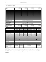
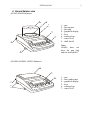
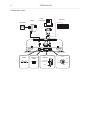
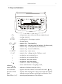
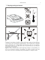
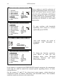
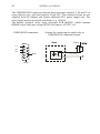
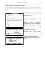
USER MANUAL 1 ____________________________________________________________________________________________________________________ AG600, AGZ600 AG100-AG500, AGZ100-AGZ500 AG1000-AG4000 AGZ1000-AGZ4000,AGZ10 USER MANUAL AG and AGZ series File: 2014-11-18 AG-100 AG0M95 GB 2 USER MANUAL ____________________________________________________________________________________________________________________ Contents: 1. General description.................................................................................................. 3 2. Completeness .......................................................................................................... 3 3. Technical data ......................................................................................................... 4 4. General balance view .............................................................................................. 5 5. Keys and indicators ................................................................................................. 7 6. Safety rules.............................................................................................................. 8 7. Preparing working environment ............................................................................... 9 8. Preparing balance to work ..................................................................................... 10 9. General operation principles .................................................................................. 11 10. Start-up .................................................................................................................. 12 11. Internal calibration ................................................................................................. 12 12. Checking the balance ............................................................................................ 14 13. Connecting a computer, printer or label printer ...................................................... 14 14. Special functions.................................................................................................... 19 14.1 Autotaring function ............................................................................................... 20 14.2 Pieces counting function....................................................................................... 21 14.3 Unit selection function .......................................................................................... 23 14.4 Percent function ................................................................................................... 24 14.5 Function for calibration with external weight / calibration options.......................... 25 14.6 Function for setting serial port .............................................................................. 29 14.7 Print settings function ........................................................................................... 31 14.8 Time and date setting function.............................................................................. 34 14.9 LCD settings function ........................................................................................... 35 14.10 Recipe function ................................................................................................... 36 14.11 Animals weighing function .................................................................................. 37 14.12 Tare setting function ........................................................................................... 38 14.13 Force unit function .............................................................................................. 39 14.14 Maximum and minimum value indication function ............................................... 40 14.15 Anti-disturbance filter function............................................................................. 41 14.16 Language selection function ............................................................................... 42 14.17 Function of comparing with preset threshold values ........................................... 43 14.18 Funkcja sumowania ważeń TOTAL .................................................................... 47 14.19 Statistical calculations function ........................................................................... 48 14.20 Funkcja wyliczenia gramatury papieru ................................................................ 50 14.21 Density measurement function (option) .............................................................. 50 14.21.1 Solid body density determination ..................................................................... 52 14.21.2 Liquid density determination ............................................................................ 54 14.21.3 Density measurement report ........................................................................... 56 15. Procell program description (demo version)........................................................... 57 16. Troubleshooting and maintenance ......................................................................... 58 Declaration of Conformity USER MANUAL 3 ____________________________________________________________________________________________________________________ 1. General description AG and AGZ series balances are destined for high accuracy weighing in laboratory practice. AG series balances are equipped with internal calibration system for accuracy control during balance operation. AGZ series balances do not have internal calibration system and can be used when legal verification is not required. All balances are metrologically tested. According to an order balances can be calibrated or legally verified. Balances with legal verification are marked with the following legal and securing items: - green metrological mark placed on the balance name plate, - notified body stamp (number of notified body) on the balance name plate, - protective seals placed on: an edge of balance name plate, the casing mounting screw and in the place of access to adjustment switch, Renewing of balance legal verification is required when protective seal is violated or after period of 3 years starting from 1 st December of year when first legal verification was performed. In order to renew legal verification please contact AXIS authorised service centre. In AGZ series balances all functions connected with internal calibration are removed (chapter 11 and 14.5). Balance classification according to PKWiU: 33.20.31. Certificates: Certificate of ISO quality system DIN EN ISO 9001:2000 Certificate of balance type approval TCM 128/06-4428 2. Completeness A standard set consist of: 1. Balance 2. Pan elements: - for balances with round pan (AG100-AG600): a pan support and a pan, - for balances with rectangular pan, AG8 (AG1000-AG4000, AGZ10): gum nuts (4pcs) and a pan, 3. Draft shield with cover (AG100-AG500), 4. Feeder 12V / 1,2A 5. User manual, guarantee card USER MANUAL 4 ____________________________________________________________________________________________________________________ 3. Technical data AG100 AGZ100 Type Capacity (Max) Min load (Min) Reading unit (d) Verification unit (e) Tare range Accuracy class Working temperature Weighing time Pan dimension Balance dimension (with legs) Balance weight Power supply Recommended external calibration weight (OIML) Type Capacity (Max) Min load (Min) Reading unit (d) Verification unit (e) Tare range Accuracy class Working temperature Weighing time Pan dimension Balance dimension (with legs) Balance weight Power Recommended external calibration weight (OIML) 100g 0,02g 0,001g 0,01g -100g AG200 AGZ200 AG300 AGZ300 AG500 AGZ500 200g 300g 0,02g 0,02g 0,001g 0,001g 0,01g 0,01g -200g -300g II +18 ÷ +33°C <3s 115mm 215(235 with legs)x345x90mm 500g 0,02g 0,001g 0,01g -500g 5kg ~230V 50Hz 6VA / =12V 800mA F2 100g F2 200g AG600 AG1000 AG2000 AGZ600 AGZ1000 AGZ2000 600g 1000g 2000g 0,5g 0,5g 0,5g 0,01g 0,01g 0,01g 0,1g 0,1g 0,1g -600g -1000g -2000g F2 200g AG3000 AGZ3000 3000g 0,5g 0,01g 0,1g -3000g F1 500g AG4000 AGZ4000 AGZ10 4000g 0,5g 0,01g 0,1g -4000g 10kg 5g 0,1g 1g -10kg II +18 ÷ +33°C <3s 150mm 165x165mm 195x180mm 215(235 with legs)x345x90mm 5kg ~230V 50Hz 6VA / =12V 800mA F2 500g F2 1000g F2 2000g F2 5000g Caution: F1 and F2 are international symbols of calibration weight classes according to O.I.M.L. Some requirements for weight accuracy are connected with those classes. USER MANUAL 5 ____________________________________________________________________________________________________________________ 4. General balance view AG100-AG600 balances: 8 1 2 3 4 5 7 1 – pan 2 – pan support 3 – pan ring 4 – graphical display 5 – keys 6 – rotating legs 7 – water level 8 – draft shield Note: AG600 does not have the pan ring and the draft shield. 6 AG1000-AG4000, AGZ10 balances: 1 2 4 5 7 6 1 – pan 2 – nuts (under pan) 4 – graphical display 5 – keys 6 – rotating legs 7 – water level USER MANUAL 6 ____________________________________________________________________________________________________________________ Connectors view: Printer or computer Feeder Keyboard ~230V/50Hz Feeder Adjustment switch ON OFF PS2 RS232C Clock 1 RxD (receiver) TxD (transmitter) 2 6 7 3 8 4 5 GND +5V 6 5 4 3 2 1 GND 9 Data Case USER MANUAL 7 ____________________________________________________________________________________________________________________ 5. Keys and indicators T 0 ENTER . 1/F1 ... 5/F5 6 / 0 7/ 8/ 9 / MENU 0/ ∧ ∨ > < I/ indicator linear indicator OFF indicator decrease of last digit - taring (enter mass subtracted from weighed mass) - zeroing (option), - confirmation / choosing an option, decimal point, numeric key / functional key, numeric key / zeroing (only for balances for direct sale), numeric key / result printout (transmission), numeric key / internal calibration, numeric key / enter menu, numeric key / change mode of balance work, navigation: go to option above, navigation: go to option below, navigation: enter into option, navigation: exit from option, switch on / switch off (standby), shows stabilization of weighing result, - indicator of balance load (0-100%), - appears after the balance is switched off with I / key, - informs that reading unit value is lower than acceptable indication error (balances with legal verification, de) Max, Min, d, e, II - metrological parameters of the balance. USER MANUAL 8 ____________________________________________________________________________________________________________________ 6. Safety rules It is necessary to follow safety rules of work with the balance shown below. Obeying those rules is the condition to avoid electrical shock or damage of the balance or connected peripheral devices. Repairs and necessary regulations can be done by authorised personnel only. To avoid fire risk use a feeder of an appropriate type (supplied with the balance) and supply voltage have to be compatible with specified technical data. Do not use the balance when its cover is opened. Do not use the balance in explosive conditions. Do not use the balance in high humidity environment. If the balance seems not to operate properly, switch it off and do not use until checked by authorised service centre. AG series balances are not allowed for use in house holds. According to current acts of low about protection of natural environment, wasted balances should not be put into waste containers together with ordinary waste. Wasted balance after operation period can be delivered to units authorised for gathering wasted electronic devices or to the place where it was bought. USER MANUAL 9 ____________________________________________________________________________________________________________________ 7. Preparing working environment +33°C +18°C Location for the balance should be chosen with care in order to limit influence of the factors that can interrupt working balance. This location has to maintain proper temperature for working balance and necessary space for its operating. The balance should stay on stable table made of material that does not influence magnetically on the balance. Rapid air blast, vibrations, dust, rapid temperature changes or air humidity over 90% are not allowed in balance surrounding. The balance should be far from heat sources and devices emitting strong electromagnetic or magnetic fields. USER MANUAL 10 ____________________________________________________________________________________________________________________ 8. Preparing balance to work 1. Take the balance, the feeder and mechanical elements of the pan out. It is recommended to keep the original scale package in order to transport the balance safely in future. 2. Place the balance on a stable ground not affected by mechanical vibrations and airflows. 3. Level the balance with 1 2 3 rotating legs 6 so that the air bubble in water level 7 at the back of the balance is in the middle. 4. (for AG100-AG600) Gently insert the mandrel of pan support 2 into balance mechanism socket through the pan ring 3 and the pan 1 on (AG600 balances have not the pan ring). 7 6 1 2 5. (for AG1000-AG4000) Place nuts 2 on mandrels that are visible in balance cover holes, put the pan 1 on nuts. 7 6 6. If the balance was taken from a lower temperature surrounding to a room with higher temperature, e.g. in winter, moisture can liquefy on the balance casing. Do not connect power supply to the balance, because this can cause damage or improper work of the balance. In this case leave the balance for at least 4 hours unplugged for acclimatization. USER MANUAL 11 ____________________________________________________________________________________________________________________ 9. General operation principles 1. Weighed sample should be placed in the centre of the pan. 2. In direct sale use (d=e), make sure that 0 zero indicator is displayed before sample is placed on the pan. If not, press 0 key and wait until the balance is zeroed and zero indicator appears. In other balances the key does not operate. 3. The balance allows taring in the whole measuring range. To tare the balance press T key (on the left or on the right). Taring does not extend measuring range, but only subtracts tare value from mass value of a sample placed on the pan. To make the control of pan load easier and to avoid crossing measurement range, the balance has a load indicator calibrated 0÷100% Max. 4. Weighing result should be read when the indicator " signalises stabilisation of a result. " lights, which 5. When the balance is not used but should be ready to work immediately, it can be switched off by pressing I/ key. The backlight of balance reading system is then switched off and the balance enters into "standby" mode, in which the balance maintains internal temperature and ability to start working with maximum accuracy. Standby mode is signalled by the OFF indicator. To switch the balance on press I/ key. 6. Balance mechanism is a precise device sensitive to mechanical shocks and strokes. Do not overload the balance more than 20% of maximum capacity. Do not press the pan with a hand. For transportation take off the pan and pan support (AG(Z)100AG(Z)600 balances) or nuts (AG(Z)1000-AG(Z)4000 and AGZ10 balances), on which the pan is placed. 7. The balance cannot be used to weigh ferromagnetic materials due to decrease of weighing accuracy. 8. After every change of balance position, level the balance and perform internal calibration. USER MANUAL 12 ____________________________________________________________________________________________________________________ 10. Start-up Plug feeder into 230V power supply socket and feeder output connector into 12V socket at back of the balance. INITIALIZATION model program version Processor test Reading EEPROM ... ... AUTOCALIBRATION . Internal calibration : please wait ... Max ... Min ... e= ... Afterwards the balance enters automatically into internal calibration mode, which is described with details in next chapter. Calibration can be terminated using CLR key. d= .. 0.000 g 0% After switching-on, the balance displays AXIS logo and performs automatic self-tests. In case of test failure balance displays tests list. Lack of mark means negative test result. 100% When internal calibration is finished, the balance enters into normal weighing mode. 11. Internal calibration The balance is equipped with internal calibration system, which general task is to maintain required measurement accuracy on the balance. Internal calibration is the process of putting internal weight on automatically by balance mechanism and correcting accuracy in balance firmware. The correction is necessary because of differences between values of gravitational acceleration in the place where the balance was manufactured and in the place where it is operated, as well as due to changes of balance level and temperature. Internal calibration is performed in the following situations: - when key is pressed, - after defined time interval (for legally verified balances - 2 hours), - after temperature change (for legally verified balances – more than 2oC). In legally verified balances time interval is set to 2 hours and defined temperature change is 2oC. In not legally verified balances those values can be set as calibration options. The reason of starting internal calibration is shown as an icon near weight picture. USER MANUAL 13 ____________________________________________________________________________________________________________________ In order to perform internal calibration proceed with the following: CALIBRATION Empty the pan. Press key twice (double pressing the key helps to avoid accidental starting calibration procedure). Internal calibration ? ( - to confirm) During calibration internal weight is put three times on and obtained results are compared. Discrepancy of results is signalled with a message and causes the balance being blocked. Until calibration process is finished do not perform any operation on the balance. Any vibrations and shocks interfere calibration process and may delay it or deteriorate accuracy of its result. CALIBRATION Internal calibration : taring ... CALIBRATION Internal calibration: internal load When internal calibration is performed successfully the balance indicates zero on the display at empty pan. Max ... Min ... e= ... d= ... 0.000 g 0% 100% Note: In order to terminate calibration process press CLR key and wait until balance mechanism is not settled in initial position. USER MANUAL 14 ____________________________________________________________________________________________________________________ 12. Checking the balance In order to confirm correctness of the balance during its operation, before starting and after finishing every measurement series it is advised to check weighing accuracy. It can be done by weighing external calibration weight or other object with exactly known mass. If exceeding of allowable measurement error is affirmed, the following things should be checked: - if the balance stands stable and it is levelled, - if the balance is exposed on rapid air blasts, vibrations, rapid temperature changes or air humidity, - if the balance is not affected directly by heat source, electromagnetic radiation or magnetic field. The cause of inaccuracy can be too low temperature of the balance as well, when it was unplugged from power supply. In this situation leave the balance switched on for several minutes in order to adjust its internal temperature. If none of above causes of inaccuracy occurs, calibration with external weight should be performed to the balance. Recommended external calibration weight (to buy for additional charge) is given in technical data table. In order to calibrate the balance with external weight in legally verified balances verification seals should be removed and another legal verification should be performed. In this case it is recommended to contact authorised service centre. Calibration with external weight is described in details in chapter 14.5. 13. Connecting a computer, printer or label printer The scale is equipped with RS232C, which can be used to connect external devices such as computer or a printer. RS232C 1 RxD (receive) TxD (transmission) 2 3 4 GND 5 6 7 8 9 housing +5V(option) When cooperating with computer, the scale sends weighing result after initialize signal from computer or after pressing key on the scale. When cooperating with a printer data is send automatically after result stabilisation, but next transmission is possible after removing previously weighted sample. When cooperating with label printer after pressing key, the scale sends instructions set for the label printer. Label number 0001, hour, data (if the clock USER MANUAL 15 ____________________________________________________________________________________________________________________ is installed and on) and nett weight. During transmission LabEL communicate is displayed. The way of sending data and transmission parameters is set using SErIAL special function. Set of send data is set using special function PrInt. The following data can be send: - Header (scale type, Max, d, e, serial number), - Operator identification number, - Successive printout number (measurement), - Identification number or product bar code, - Number of pcs (PCS function only), - Single detail mass (PCS function only), - Nett weight, - Tare (package mass), - Gross weight, - Total mass (Total function only). Computer must have a special program for cooperation with data from a scale. Dedicated programs are also offered by AXIS. Except RS232C joint, the scale can be equipped with USB or Wi-Fi interface. Needed controllers and instruction can be found on a CD supplied with Axis scales. Detailed protocol description LonG protocol Communication parameters: 8 bits, 1 stop bit, no parity, baud rate 4800bps, initialising signal (data send order) – correspond to press key ComputerScale: S I CR LF (53h 49h 0Dh 0Ah), ScaleComputer: scale response according to description below (16 bytes): Byte Byte Byte Byte Byte Byte Byte Byte Byte Byte Byte 1 2 34 5÷9 10 11 12 13 14 15 16 - sign „-” or space space digit or space digit, decimal point or space digit space k, l, c, p or space g, b, t, c or % space CR LF 16 USER MANUAL ____________________________________________________________________________________________________________________ Attention: Network number different than zero (Port/nr function) changes scale working mode: communication with a computer is possible after logging the scale in with 02h scale number command. To log the scale out use 03h command. For example: Using a program to test RS232 interface ( program is available in www.axis.pl / programy komputerowe ) for scale number 1 please write: $0201 to log in, then SI, and write: $03 to close communication. Asking about scale presence in system (testing scale connection with computer): ComputerScale: S J CR LF (53h 4Ah 0Dh 0Ah), ScaleComputer: M J CR LF (4Dh 4Ah 0Dh 0Ah), Displaying a inscription on scale’s display (text communicate from computer): ComputerScale: S N n n X X X X X X CR LF (53h 4Eh 0Dh 0Ah), nn-displaying time in seconds; XXXXXX-signs to display ScaleComputer: M N CR LF (4Dh 4Eh 0Dh 0Ah), Scale tarring (calling T key press) : ComputerScale: S T CR LF (53h 54h 0Dh 0Ah), ScaleComputer: without response, Scale zeroing (calling 0 key press): Computer Scale: S Z CR LF (53h 5Ah 0Dh 0Ah), Scale Computer: without response, Scale turning on / off (calling I/ key press): Computer Scale: S S CR LF (53h 53h 0Dh 0Ah), Scale Computer: without response, Entering to special function menu (calling MENU key press): Computer Scale: S F CR LF (53h 46h 0Dh 0Ah), Scale Computer: without response, Setting low threshold value (option): Computer Scale: S L D1...DN CR LF (53h 4Ch D1...DN 0Dh 0Ah) D1...DN – threshold value, maximum 8 characters („-” – negative value, digits, dot – decimal separator), number of digits after dot should be the same as on scale display, Scale Computer: without response, Example: in order to set low threshold 1000g in scale B1.5 (d=0.5g) the following order should be sent: S L 1 0 0 0 . 0 CR LF (53h 4Ch 31h 30h 30h 30h 2Eh 30h 0Dh 0Ah), USER MANUAL 17 ____________________________________________________________________________________________________________________ in order to set low threshold 100kg in scale B150 (d=50g) the following order should be sent: S L 1 0 0 . 0 0 CR LF (53h 4Ch 31h 30h 30h 2Eh 30h 30h 0Dh 0Ah),), Setting high threshold value (option): Computer Scale: S H D1...DN CR LF (53h 48h D1...DN 0Dh 0Ah), D1...DN – threshold value (see ) Scale Computer: without response. Connecting cable WK-1 (scale – computer / 9-pin interface): BALANCE COMPUTER Connecting cable WD-1 (scale with AXIS printer): BALANCE PRINTER Setting internal AXIS printer swithces: SW-1 on SW-2 off SW-3 SW-4 SW-5 SW-6 SW-7 SW-8 on off off on off off USER MANUAL 18 ____________________________________________________________________________________________________________________ ELtron protocol Transmission parameters: 8 bits, 1 stop bit, no parity, baud rate 9600bps, After using key in scale: ScaleLabel printer : set of instruction in EPL-2 language that initialize label printing: US FR"0001" ? mm:gg rrrr.mm.dd masa P1 - Steering instruction Label number define instruction Instruction that starts list of variable signs 5 signs: minutes:hour 10 signs: year.month.day 10 signs: scale indication+ mass unit Steering instruction Attention: 1. Except variable signs constant signs also can be inscribed for example factory name, product name and so on. 2. In standard one label pattern is possible to prinout (number 0001). Using bigger amount of patterns (other label numbers) is possible thanks to LAbEL special function. 3. To achieve label printout, label printer must have inscribed label pattern (label pattern is created on computer and using computer it is saved to label printer memory). Label pattern is designed by ZEBRA DESIGNER program which is supplied together with label printer. Scales parameters and transmission protocol must corespond to label printer type. USER MANUAL 19 ____________________________________________________________________________________________________________________ 14.Special functions All balances, beside basic metrological functions like weighing and taring, are equipped with set of special functions. Basic set of special functions is shown below. In respect of metrology calibration with external weight is important special function. To avoid showing too many functions in menu, user can choose which functions should be displayed in menu and should not. Menu settings function is used for this. USER FUNCTIONS&OPT. Menu settings Default settings Exit USER FUNCTIONS&OPT. / ENABLING Autotaring PCS counting Unit selection Percent Calibration Serial Port Print settings Time&Date settings LCD settings ... Exit USER FUNCTIONS&OPT. Autotaring PCS counting Serial Port Menu settings Default settings Exit When Menu key is pressed, the balance shows special functions menu. Function activation is performed with the cursor (dark background). In factory settings user can only choose from Menu setting and Default settings. In Menu settings window choose the functions, which should be currently used in menu. The choice is made by selecting a function with a cursor and pressing ENTER key. The functions selected to use in menu should be signified with mark. To quickly go from functions menu to Menu settings window press key. For moving the cursor, navigation keys ∨ and ∧ are used. - means the function is active - means the function is inactive Pressing ENTER key causes opening a window of function selected with the cursor. When < key is pressed, the balance returns to previous window USER MANUAL 20 ____________________________________________________________________________________________________________________ 14.1 Autotaring function This function automatically keeps zero indication when a pan is empty or zero indication was forced with T key. USER FUNCTIONS&OPT. Press Menu key to enter the user function menu, choose Autotaring and press ENTER key. Autotaring PCS counting . . . USER FUNCTIONS&OPT. \ AUTOTARING 1. Activate 2. Correction range: 3. Exit 2.0 d/sec Choose Correction range using ∨ and ∧ keys and press ENTER key. Enter maximum zero flow to be automatically corrected by Autotaring function. Allowed range is 0.5 ÷ 5 (in balance reading units per second). USER FUNCTIONS&OPT. \ AUTOTARING 1. Activate 2. Correction range: 3. Exit Max ... Min ... 2.0 d/sec e= ... d= .. AUT 0.000 g 0% 100% Choose Activate option with a cursor and press ENTER. Indications that are near to zero will be automatically corrected and zero indication will be maintained despite changing environmental conditions (temperature, air humidity, etc.) To stop the function press Menu key to enter user functions menu, choose Autotaring function and then choose Deactivate option. USER MANUAL 21 ____________________________________________________________________________________________________________________ 14.2 Pieces counting function Pieces counting function allows determining the number of items in weighed sample according to: 1. Reference sample with known number of pieces (unitary mass is not known), 2. Unitary mass of an item. 1. Unitary mass is not known but user has got a sample. Max ... Min ... e= ... d= .. II 2.000 g 0% Place a sample with known number of pieces on the pan. 100% USER FUNCTIONS&OPT. Autotaring PCS counting . . . Press Menu key to enter the user function menu, choose PCS counting with the cursor and press ENTER key. USER FUNCTIONS&OPT. \ PCS COUNTING 1.Activate 2.Sample quantity 3.Unit weight : 4.Exit none USER FUNCTIONS&OPT. \ PCS COUNTING 1.Activate 2. Sample quantity : 3. Unit weight 4. Exit Max ... Min ... Using numeric keys enter the quantity of pieces in the sample and press ENTER key. 12 e= ... d= .. PCS 12 pcs 0% Choose Sample quantity option and press ENTER key. 100% The balance calculates unitary mass of an item (unit weight) basing on given number of pieces and sample weight and then shows number of pieces on the display. If a change of sample parameters is not required during next use of the function, start the function choosing Activate option and pressing ENTER key. To stop the function press Menu key, choose PCS counting function and then choose Deactivate option. Note: In order to show mass value temporarily and return to pieces indication press key. USER MANUAL 22 ____________________________________________________________________________________________________________________ 2. Unitary mass of an item (unit weight) is well known. USER FUNCTIONS&OPT. Autotaring PCS counting Press Menu key to enter the user function menu, choose PCS counting with the cursor and press ENTER key. . . . USER FUNCTIONS&OPT. \ PCS COUNTING Choose Unit weight option with the cursor and press ENTER key. 1.Activate 2.Sample quantity 3.Unit weight : 4.Exit 0.198 g USER FUNCTIONS&OPT. \ PCS COUNTING 1.Activate 2.Sample quantity 3.Unit weight 4.Exit Max ... Min ... : 0.2 g e= ... d= .. 0 pcs 0% Enter unit weight value using numeric keys and press ENTER to accept it. The unit weigh value is stored in balance memory until switching the balance off. The balance displays pieces quantity. 100% Note: To correct wrong digits when entering unit weight, press < key to delete the last number or CLR to leave the function and proceed from the beginning. INSTRUKCJA OBSŁUGI 23 14.3 Unit selection function The function allows choosing the unit of mass indication. The following units can be selected: - gram (g) - kilogram (kg) - miligram (mg) - carat: 1ct=0,2g - pound: 1lb=453,592374g - grain: 1gr=0,06479891g - ounce: 1oz=28,349523g - ounce troy: 1ozt=31,1034763g - pennyweight: 1dwt=1,55517384g USER FUNCTIONS&OPT. Autotaring PCS counting Unit selection Press Menu key, choose Unit selection with the cursor and press ENTER key. . . . Exit USER FUNCTIONS&OPT. \ UNIT SELECTION 1. Unit 2. Exit : gram Press > key to enter unit field. g USER FUNCTIONS&OPT. \ UNIT SELECTION 1. Unit 2. Exit : < gram > g Using > and < keys choose proper unit and press ENTER key. Press < key or choose Exit option to return to weighing. USER MANUAL 24 ____________________________________________________________________________________________________________________ 14.4 Percent function The function allows replacing indication in mass units with percentage values according to assigned reference mass. Max ... Min ... e= ... d= .. II Put a mass referenced to 100% on the pan. 20.000 g 0% 100% USER FUNCTIONS&OPT. Press Menu key, choose Percent with the cursor and press ENTER key. Autotaring PCS counting Unit selection Percent . . . USER FUNCTIONS&OPT. \ PERCENT Choose Activate option with the cursor and press ENTER key to display percentage indication. 1. Activate 2. Exit % Max ... Min ... e= ... d= .. PRO 100.000 % 0% II To stop the function enter Percent function menu and use Deactivate option. 100% Comments: 1. In order to show mass value in grams temporarily and return to percentage indication press key. 2. According to a mass referenced to 100% percentage indications will be displayed in different formats. For reference mass in range 0÷3,5% of balance capacity, displayed result will be shortened of two decimal places, in range 3,5÷35% - shortened of one decimal place, above 35% - in full accuracy. USER MANUAL 25 14.5 Function for calibration with external weight / calibration options Calibration with external weight should be performed if balance accuracy after internal calibration is not satisfactory. Calibration weight stated in technical data table for the balance (or of better accuracy) with valid verification certificate should be used then. Calibration of legally verified balance requires violating a mark used to protect an access to adjustment switch and results in loosing legal verification. To renew legal verification of the balance, it is necessary to contact a service centre or notified body. Adjustment switch ON Mark OFF In legally verified balances performing calibration requires changing adjustment switch position, which is placed behind protecting mark (sticker) of a notified body. An access to the switch is possible only after removing the mark. Therefore, balance calibration causes lost of legal verification and, in consequence, the necessity of renew legal verification in the nearest notified body or in place where the balance is used. Before proceeding with calibration of legally verified balance, adjustment switch should be set to ON position using thin screwdriver (the balance will display the message Calibration switch ON! and generate a sound). When calibration process, described on next page, is finished, the balance will display the message Calibration switch ON!. Adjustment switch should be set to OFF position using thin screwdriver (the balance will move to weighing). USER MANUAL 26 ____________________________________________________________________________________________________________________ Steps during calibration with external weight: USER FUNCTIONS&OPT. Autotaring PCS counting Press Menu key, choose Calibration option with the cursor and press ENTER. . . . Calibration . . . USER FUNCTIONS&OPT. \ CALIBRATION 1. External calibration 2. External load 3. Time of calibration 4. Temp. of calibration 5. Report printout 6. Exit : 200g : 2h : 2.0oC Check if External load value matches the value of external weight used for calibration. If not, choose External load option and enter correct value. Choose External calibration option with the cursor and press ENTER. CALIBRATION Wait until taring process is finished. External calibration: taring ... CALIBRATION External calibration: Put external load _200.000 g Put calibration weight displayed value on. matching CALIBRATION External calibration: take off ext. load Take off the calibration weight. CALIBRATION Wait until internal calibration is finished. Internal calibration: please wait ... Max ... Min ... e= ... d= ... 0.000 g 0% 100% The balance is ready to work. USER MANUAL 27 Calibration options (internal and external): Except of Report printout, calibration options are available after changing position of adjustment switch. USER FUNCTIONS&OPT. Autotaring PCS counting Press MENU key, choose Calibration option with the cursor and press ENTER. . . . Calibration . . . USER FUNCTIONS&OPT. \ CALIBRATION 1. External calibration 2. External load 3. Time of calibration 4. Temp. of calibration 5. Report printout 6. Exit : 200g : 2h : 2.0oC USER FUNCTIONS&OPT. \ CALIBRATION 1. External calibration 2. External load 3. Time of calibration 4. Temp. of calibration 5. Report printout 6. Exit : 200g : 2h : 2.0oC USER FUNCTIONS&OPT. \ CALIBRATION 1. External calibration 2. External load 3. Time of calibration 4. Temp. of calibration 5. Report printout 6. Exit : 200g : 2h : 2.0oC External load option allows entering the value of external weight used for calibration. Choose External weight option with the cursor, press ENTER key and use > and < keys to select desired value. Several standard values are available, but it is advised to use as great weight value as possible. Time of calibration option allows defining the time, after which the balance performs internal calibration automatically. Temp. of calibration option allows to define the change of environment temperature, at which internal calibration will be performed automatically. Values of the options are selected as with external load above. If external printer is connected to the balance, Report printout option allows obtaining calibration data of the balance, which proofs that calibration process was performed correctly and may be useful for balance diagnostics. USER MANUAL 28 ____________________________________________________________________________________________________________________ The form of calibration report printout Date : ... Time: ... -----------Calibration report----------- Date of production: ... Scale type: Serial number: ... Program version: ... Adjustation no.: ... Date of adjustation: Temperature of adjust.: Factory external weight: ... - external weight value registered during factory calibration Factory internal weight: ... - internal weight value registered during factory calibration Current external weight: ... - external weight value registered during last calibration Current internal weight: ... - internal weight value registered during last external calibration Weight difference: ... - difference between internal weight values: factory value–current value USER MANUAL 29 14.6 Function for setting serial port To enable cooperation with a printer (or a computer), transmission parameters in both devices have to be the same. This function allows to set the following transmission parameters: - send and receive baud rate (1 200 115 200bps), - number of bits in single character (7 or 8 bit), - parity control (none, even, odd), - protocole type (default protocol is LONG), - transmission mode (after pressing key if result is stable, after pressing key independently of stable result, automatically after putting a load on the pan and weighing result stabilisation, continuous transmission every 0,1s). USER FUNCTIONS&OPT. Autotaring PCS counting Press MENU key, choose Serial Port with the cursor and press ENTER key. . . . Serial port . . . USER FUNCTIONS&OPT./SERIAL PORT 1. Port 1 2. Port 2 3. Wyjście SERIAL PORT \ PORT 1 1. Baudrate 2. Bits 3. Parity 4. Protocol 5. Sending mode 6. Exit : 4800 : 8-bit : none : LONG : button+stab. SERIAL PORT \ PORT 1 1. Baudrate 2. Bits 3. Parity 4. Protocol 5. Sending mode 6. Exit : <4800> : 8-bit : none : LONG : button+stab. Check if port interface settings are compliant with parameters of connected external device. If not, using ∨ and ∧ keys move the cursor on parameter that should be set and press ENTER key. Set proper value of parameter using < and > keys and press ENTER. Leave the function by pressing MENU key or using Exit option. USER MANUAL 30 ____________________________________________________________________________________________________________________ USER FUNCTIONS&OPT Autotaring PCS counting . . . Label Exit USER FUNCTIONS&OPT \ LABEL 1. Address 2. Exit : USER FUNCTIONS&OPT \ LABEL 1. Address 2. Exit : 2345 USER FUNCTIONS&OPT \ LABEL 1. Address 2. Exit : 2345 If the protocol is set to ELTRON (cooperation with label printer), in user function menu Label function activates. This protocol allows printing scale indication and optionally date and time on label printer, as variable texts. Other data, e.g. company address, product name, its bar code can appear on label as constant fields. Label forms used by user, named as a numeric value (max. 4 digits) should be previously stored in printer memory according to printer user manual. Choosing label form is performed by entering label number using LAbEL function. USER MANUAL 31 14.7 Print settings function This function allows to attach the following information to a printout: - numbers of succesive measurements, - date and time near each measurement. USER FUNCTIONS&OPT. Autotaring PCS counting . . . Press MENU, choose Print settings with the cursor and press ENTER key. Print settings . . . USER FUNCTIONS&OPT. \ PRINT SETTINGS Header Values Footer ID1 ID2 ID3 Exit Select desired options using ∨ and ∧ keys and pressing ENTER key. Use numeric keys to fill ID1-3 field values. To delete last character use < key. Header - the entrance to the printout header definition menu; least one option in the Header definition menu is checked. sign indicates if at Header definition menu \ PRINT SETTINGS \ HEADER Blank line Mode name Date & time Balance type Serial number ID1 ID2 ID3 Signature Exit An element is checked/unchecked if ENTER key is pressed. Checked element will appear in a printout header if the Header element in Values definition menu is checked as well. USER MANUAL 32 ____________________________________________________________________________________________________________________ An example of a full header printout: --------------- WEIGHING --------------Date : 2000-04-25 Time : 22:32 Scale type : AGNZ200 Serial number : 123456 ID1 string ID2 string ID3 string Signature ..................................... blank line mode name date and time balance type serial number ID1 ID2 ID3 signature Values - the entrance to printout values definition menu; least one option in Values definition menu is checked. sign indicates if at Values definition menu \ PRINT SETTINGS \ VALUES Header Blank line ID1 ID2 ID3 Measur. number Tare Net Gross LCD result Exit An element is checked/unchecked if ENTER key is pressed. Tare, Net and Gross values are always expressed in grams. The value LCD result always indicates display state with an active unit. An example of a full values printout (without header): ID1 string ID2 string ID3 string Measurement number : 1 T 0.0000 g N 66.7425 g B 66.7425 g LCD 333.7125 ct blank line ID1 ID2 ID3 measurement number tare net gross LCD result USER MANUAL 33 ____________________________________________________________________________________________________________________ Footer - the entrance to the printout footer definition menu; least one option in Footer definition menu is checked. sign indicates if at Footer definition menu \ PRINT SETTINGS \ FOOTER Blank line Mode name Date & time Balance type Serial number ID1 ID2 ID3 Signature Dash line 3 3 blank lines Exit An element is checked/unchecked if ENTER key is pressed. An example of a full printout footer : ------------ PCS COUNTING ------------Date : 2000-04-25 Time : 23:05 Scale type : AGNZ200 Serial number : 123456 ID1 string ID2 string ID3 string Signature ..................................... --------------------------------------- blank line mode name date and time balance type serial number ID1 ID2 ID3 signature separating line 3 empty lines ID1, ID2, ID2 - strings (max. 20 characters) typed using PS2 keyboard or balance numeric keypad, which works similarly to mobile keyboard (characters coupled with relevant key appear in first line of the display after the key is pressed); typed string is approved with ENTER key, last character can be deleted using < key. USER MANUAL 34 ____________________________________________________________________________________________________________________ 14.8 Time and date setting function The function allows to set current date and time, used in printouts: USER FUNCTIONS&OPT. Autotaring PCS counting . . . Press MENU, choose Time&date setting with the cursor and press ENTER key. Time&date setting . . . USER FUNCTIONS&OPT.\TIME&DATE SETTING 1. Time 2. Date 3. Code 4. 12/24 5. Form 6. Exit : : 09:11:03 2006-03-31 : : 24H YYYY-MM-DD USER FUNCTIONS&OPT.\TIME&DATE SETTING 1. Time: 2. Date 3. Code 4. 12/24 5. Form 6. Exit : 09:11:03 2006-03-31 : : 24H YYYY-MM-DD Select desired option using ∨ and ∧ keys and press ENTER. User can choose from: Time – entering time, Data – entering date, CODE – securing access for changing data, 12/24 – time format selection (12 hours or 24 hours), Form. – change data format (YYYY-MM-DD=year-month-day) Enter current values using numeric keys. Press ENTER to accept. USER MANUAL 35 ____________________________________________________________________________________________________________________ 14.9 LCD settings function This function allows to set contrast and backlight of balance display: USER FUNCTIONS&OPT. Autotaring PCS counting Press MENU, choose LCD settings with the cursor and press ENTER key. . . . LCD settings . . . USER FUNCTIONS&OPT. \ LCD SETTINGS 1. Contrast 2. Backlight 3. Exit : : 8 ON Choose Contrast option using ∨ and ∧ keys and press ENTER key. USER FUNCTIONS&OPT. \ LCD SETTINGS 1. Contrast 2. Backlight 3. Exit : : < ON > 12 Select desired contrast value using < and > keys. Press ENTER to accept. USER FUNCTIONS&OPT. \ LCD SETTINGS 1. Contrast 2. Backlight 3. Exit : : 12 ON Choose Backlight option using ∨ and ∧ keys and press ENTER key. USER FUNCTIONS&OPT. \ LCD SETTINGS 1. Contrast 2. Backlight 3. Exit : : 12 <OFF> Turn display Backlight on or off using ∨ and ∧ keys. Press ENTER to accept. USER MANUAL 36 ____________________________________________________________________________________________________________________ 14.10 Recipe function This function allows for weighing few ingredients in sequence in one vessel, with the possibility of continuous reading of summary mass value of all ingredients weighed so far. Press MENU key to enter the user functions menu, select Recipe with cursor and press ENTER. USER FUNCTIONS&OPT. Autotaring PCS counting . . . Using ∨ and ∧ keys, move cursor to Activation and press ENTER. Recipe USER FUNCTIONS&OPT. \ RECIPE 1. Activate 2. Reset 3. Exit Max ... =0.000g n=0 Min ... e= ... d= .. SUM 0.000 g 0% 100% The balance is ready for weighing the successive ingredients, and after each ingredient it is necessary to press T key. It will zero the balance indications. On the left side the sum of previously weighed ingredients () and their number (n) is displayed. To read the total mass of all weighed ingredients use key (pressing it again will cause return to ingredient weighing). USER RECIPE To finish the FUNCTIONS&OPT. function operation,\ press MENU to enter the user functions menu, select Recipe function, and select Deactivation option. 1. Deactivate 2. Reset 3. Exit Total weight: 0.000g Number of ingred.: 0 USER MANUAL 37 ____________________________________________________________________________________________________________________ 14.11 Animals weighing function This function allows for weighing of an animal, moving on the balance, by averaging of momentary values, measured by the balance. The samples number and sampling time, as well as operation mode are set by the balance operator. USER FUNCTIONS&OPT. Press MENU key to enter the user functions menu, select Animals weighing with cursor and press ENTER. Autotaring PCS counting . . . Animal weighing USER FUNCTIONS&OPT. \ ANIMAL 1. Activate 2. Number of samples: 1 3.Sampling time: 0.1 sek 4.Mode: autom. 5.Start treshold: 5.000g 6. Exit USER FUNCTIONS&OPT. \ ANIMAL 1. Activate 2. Number of samples: 1 3.Sampling time: 0.1 sek 4.Mode: <autom.> 5.Start treshold: 5.000g 6. Exit USER FUNCTIONS&OPT. \ ANIMAL 1. Activate 2. Number of samples: 1 3.Sampling time: 0.1 sek 4.Mode: autom. 5.Start treshold: 5.000g 6. Exit Max ... Result 0% Min ... e= ... Using ∨ and ∧ keys, move cursor to Samples number, press ENTER and type in the value with digital keys. Finish by pressing ENTER. In the same way set the sampling time (minimum time is 0.1 s). Move cursor to Operation mode and using < and > keys select the process beginning method: - manual – after pressing ENTER, - autom. – after exceeding Operation threshold. Confirm by pressing ENTER. As the Operation threshold value enter the value, which will be for sure exceeded after placing the animal on the balance, e.g. 50% of the smallest animal weight. Using ∨ and ∧ keys, move cursor to Activation and press ENTER. d= .. 10.123 g 100% To finish the function operation, press MENU to enter the user functions menu, select Animals weighing function, and select Deactivation option USER MANUAL 38 ____________________________________________________________________________________________________________________ 14.12 Tare setting function This function enables to measure gross weight of a sample placed in a container of a known weigh value (stored in the memory) and to display calculated net weight of the sample. Tare value may be entered using the keypad or by sampling container weight from the pan. Entering tare value using keys: USER FUNCTIONS&OPT.\ TARE SETTING 1. Activate 2. Tare from scale 3. Tare value: 4. Exit USER FUNCTIONS&OPT.\ TARE SETTING 1. Activate 2. Tare from scale 3. Tare value: 9.8 4. Exit USER FUNCTIONS&OPT.\ TARE SETTING 1. Activate 2. Tare from scale 3. Tare value: 9.800g 4. Exit Max ... Min ... e= ... d= .. NET This function enables to measure 10.123 g 0% 100% After pressing MENU key and choosing function Entering tare using ENTER key following options will display: - Activate –function activation (after entering tare from scale the option is automatically activated), - Tare from scale – scale takes actual weight from pan as tare, - Tare value – manual inserting tare value, - Out – out from function. Using keys ∨ and ∧ move coursor on positions Tare value and by pressing ENTER confirm choice. Insert tare value using numerical keys and confirm using ENTER key. To activate function choose Activate option. The balance will automatically come back to weighing and above weighing result a sign NET will show up. USER MANUAL 39 ____________________________________________________________________________________________________________________ 14.13 Force unit function Function activation causes displaying result in force units (N). USER FUNCTIONS&OPT.\ STRENGHT UNIT 1. Activate 2. Exit N Press MENU key. Using ENTER key choose Strenght unit function. Choose Activate option and confirm using ENTER. Attention: Units converting from mass (kg) to force (N) is made for acceleration of gravity (g=9,80665m/s2): 1N0,101971 kg USER MANUAL 40 ____________________________________________________________________________________________________________________ 14.14 Maximum and minimum value indication function This function allows for keeping the maximum value, indicated by the balance, on the display. Press MENU key to enter the user functions menu, select Maximum/minimal value with cursor and press ENTER. USER FUNCTIONS&OPT. Autotaring PCS counting . . . Maximal/minimal value USER FUNCTIONS&OPT. \ MAXIMAL VALUE 1. Activate 2. Reset 3. Mode 4. Exit Max ... The balance is ready for weighing, but the display keeps the highest (or minimal) value, measured since the function activation or use of Reset option. : MAX Min ... e= ... d= .. 0.000 g 0% Using ∨ and ∧ keys, move cursor to Activation and press ENTER. 100% To read the mass, currently placed on the balance, use key. Reuse of that key cause return to the maximum value. USER FUNCTIONS&OPT. \ MAXIMAL VALUE 1. Deactivate 2. Reset 3. Mode 4. Exit : MAX To finish the function operation, press MENU to enter the user functions menu, select Maximum value function, and select Deactivate option. USER MANUAL 41 ____________________________________________________________________________________________________________________ 14.15 Anti-disturbance filter function This function allows using digital filter with selected intensivity during weighing. Filter reduces the influence of mechanical vibrations (air blasts, base vibrations) on measurement result. USER FUNCTIONS&OPT\FILTER ACTIVATION 1. Activate 2. Filter type : <10> 3. Exit USER FUNCTIONS&OPT\FILTER ACTIVATION 1. Activate 2. Filter type : 10 3. Exit Press MENU key and choose Filter activation function. Choose Filter type position and choose (using key < and >) filter intensivity from weak (10) to strongest (40). Next to start scale working with filter on choose Activate position using ENTER key. USER MANUAL 42 ____________________________________________________________________________________________________________________ 14.16 Language selection function This function allows for language selection for messages and print purposes. USER FUNCTIONS&OPT. Autotaring PCS counting . . . Press MENU key, select Language selection with cursor and press ENTER. Language Exit USER FUNCTIONS&OPT. \ LANGUAGE Polish English German Russian Ukrainian Czech Spanish French Exit Using ∧ and ∨ keys, select proper language and press ENTER. . USER MANUAL 43 ____________________________________________________________________________________________________________________ 14.17 Function of comparing with preset threshold values This function allows to compare the weighing result with two, previously programmed values: upper and lower threshold. The comparison result is signalled with the messages MIN, OK or MAX on the display. If the weighing result is: - smaller than lower threshold – the balance signals MIN, - between thresholds – the balance signals OK and emits acoustic signal, - bigger than the upper threshold – the balance signals MAX. - smaller than zero threshold (no load) – none of above messages appears. USER FUNCTIONS&OPT. Autotaring PCS counting . . . Streshold signalisation Press MENU key to enter the user functions menu, select Threshold signalling with cursor and press ENTER. USER FUNCTIONS \ TRESHOLD SIGNAL. 1. Activate 2. Zero treshold : 3. Min treshold : 4. Max treshold : 5. Outputs mode : 6. Buzzer : 7. LCD flashing : 8. Exit none none none none none OFF Using ∨ and ∧ keys, move cursor to Zero threshold option and press ENTER. USER FUNCTIONS \ TRESHOLD SIGNAL. 1. Activate 2. Zero treshold : 3. Min treshold : 4. Max treshold : 5. Outputs mode : 6. Buzzer : 7. LCD flashing : 8. Exit 5 none none none none OFF Enter the indications value, below which the balance is considered unloaded (no signalisation) and press ENTER. In the same way enter the values for Min threshold and Max threshold. USER FUNCTIONS \ TRESHOLD SIGNAL. 1. Activate 2. Zero treshold : 3. Min treshold : 4. Max treshold : 5. Outputs mode : 6. Buzzer : 7. LCD flashing : 8. Exit 5g 90g 110g <signalling> stable OK OFF The Outputs mode option is used for setting the THRESHOLDS connection operation mode (see below). The appropriate mode is selected with < and > keys, confirmation – with ENTER key. USER MANUAL 44 ____________________________________________________________________________________________________________________ USER FUNCTIONS \ TRESHOLD SIGNAL. 1. Activate 2. Zero treshold : 3. Min treshold : 4. Max treshold : 5. Outputs mode : 6. Buzzer : 7. LCD flashing : 8. Exit 5g 90g 110g signalling <stable OK> OFF Buzzer option is used for selection of acoustic signalling method. Selection of Stable OK option means acoustic signal activation after indications stabilisation in range signalled as OK. It is possible to activate the signal immediately after exceeding the threshold, or total signal deactivation. USER FUNCTIONS \ TRESHOLD SIGNAL. 1. Activate 2. Zero treshold : 3. Min treshold : 4. Max treshold : 5. Outputs mode : 6. Buzzer : 7. LCD flashing : 8. Exit Max ... Min ... 5g 90g 110g signalling stable OK OFF e= ... To start working with thresholds signalling, move cursor to Activate option and press ENTER. d= .. After each loading, the result of comparing with thresholds is signalled. 3 2 1 100.000 g 0% 100% USER FUNCTIONS \ TRESHOLD SIGNAL. 1. Deactivate 2. Zero treshold : 3. Min treshold : 4. Max treshold : 5. Outputs mode : 6. Buzzer : 7. LCD flashing : 8. Exit 5g 90g 110g signalling stable OK OFF To finish the function operation, press MENU to enter the user functions menu, select Threshold signalling function, and select Deactivation option. If the balance is equipped with THRESHOLDS control connection, the comparison result may be used to control the external optical signalling device, or other external devices. On the outputs P1 and P2 the short-circuit states appear, which depend on comparison results of balance indications with threshold values. The available operation modes are shown on the states chart. INSTRUKCJA OBSŁUGI 45 ____________________________________________________________________________________________________________________ THRESHOLDS outputs states chart (with increasing balance load): 1. Signalling device mode: Outputs: P1 zero treshold Min thresholdI P2 Min threshold Max thresholdI P3 Max threshold 2. Impulse mode (approx. 2 sec.): Outputs: 2s. P1 Min threshold 2s. P2 Max threshold P3 zero treshold 3. Level mode: Outputs: P1 zero treshold Min threshold P2 Min threshold Max threshold P3 Max treshold INSTRUKCJA OBSŁUGI 46 ____________________________________________________________________________________________________________________ The THRESHOLDS connection contains three transoptor outputs P1, P2 and P3 of open collector type, with load capacity 25mA/24V. The connected relays are not supplied from the balance and require additional 24V power supply unit. The relays inputs must be protected with diodes, e.g. 1N4148. The balance producer offers ready electronic PCB MS3K/P, which contains RM96P relays with input voltage DC24V and output: AC250V, 8A. THRESHOLD connection Scheme for connecting the single relay to THRESHOLDS connection output Scale Relay P1 P2 P3 GND Shield Imax < 25mA INSTRUKCJA OBSŁUGI 47 ____________________________________________________________________________________________________________________ 14.18 Funkcja sumowania ważeń TOTAL The function allows calculating total weight for series of measurements, which can be greater than scale capacity. It allows calculating total weight as well as average value. Press MENU key to enter user functions, choose Total calculation and press ENTER. USER FUNCTIONS Autotaring PCS counting . . . Total calculation USER FUNCTIONS \ TOTAL CALCULATION 1. Activate 2. Reset 3. Mode: 4. Printout: 5. Exit Max ... =0.000g n=0 Min ... e= ... d= .. TOT 0.000 g 0% 100% TOTAL REPORT 2011-09-21 9:20 TOTAL = Number of meas. = Average value = F1 PRINT F3 DONE F5 EXIT Using ∨ and ∧ keys move cursor to Activate and press ENTER. Balance is ready for weighting following pieces. After weighting each object press T key (manual mode). This will cause scale indications zeroing. On the left side of the display sum of earlier measurements is shown () and quantity of them (n). Automatic mode doesn’t require pressing T key after each measurement. Printout option enables automatic printout after each measurement. In order to readout function report use key. INSTRUKCJA OBSŁUGI 48 ____________________________________________________________________________________________________________________ 14.19 Statistical calculations function This function allows for calculations of mean value, standard deviation, relative standard deviation, maximum and minimum value, and making the histogram of performed series of measurements. Press MENU key to enter the user functions menu, select Statistics with cursor and press ENTER. USER FUNCTIONS&OPT. Autotaring PCS counting . . . Statistic USER FUNCTIONS&OPT.\ STATISTIC 1. Activate 2. Reset 3. Mode: autom. 4. Printout: ON 5. Number of samples 6. Nominal value 7. Tolerance 8. Tare after stat. USER FUNCTIONS&OPT.\ STATISTIC 1. Activate 2. Reset 3. Mode: 4. Printout: 5. Exit <autom.> ON USER FUNCTIONS&OPT.\ STATISTIC 1. Activate 2. Reset 3.Mode: 4. Printout: 5. Exit n=1 Max ... AUTO 0% The balance is ready for the series of samples measurements, for which the statistical parameters will be calculated. autom. ON Min ... e= ... Using keys ∨ and ∧ move cursor to Operation mode, and using < and > keys select the process beginning method: - manual – after pressing ENTER, - autom. – after indications stabilization. Confirm by pressing ENTER. When required, move cursor to Print and select: - ON – printing of successive measurements, - OFF – successive measurements without printing. Confirm by pressing ENTER. The following options enable inserting maximal quantity of samples, inserting nominal value and sample tolerance in %. Using ∨ and ∧ keys, move cursor to Activate and press ENTER. d= .. 0.000 g 100% To perform the measurement just put the sample, wait for stabilization and remove sample. The successive results are sent to the printer. INSTRUKCJA OBSŁUGI 49 ____________________________________________________________________________________________________________________ STATISTICS – RESULTS 2011-10-04 14:43 Number of samples Average value Stand. deviation Relative deviation Minimal value Maximal value F1 PRINT 1 2 3 4 5 = = = = = = F2 CHART F3 DONE F5 EXIT 7,5476 7,5480 7,1902 6,8227 6,4719 The individual measurements results are printed during performing (option: Print ON). After pressing F1 key the statistical parameters are printed. ------------------------------------------------------ Number of samples = 5 Average value = 7.11608 g Stand. deviation = 0.93771 g Relative deviation = 13.18 % Minimal value = 6.4719 g Maximal value = 7.5480 g i 1 2 3 4 5 2 0 MIN MAX To read the statistical parameters, press MENU key. It will display report STATISTICS – RESULTS. n 2 1 0 2 1 F2 key prints the histogram. Table on the left shows division into subranges (i) and numbers of samples (n) in the individual subranges. Return to report displaying takes place after pressing CLR key. To finish the function operation, press MENU to enter the user functions menu, select Statistics function, and select Deactivation option. INSTRUKCJA OBSŁUGI 50 ____________________________________________________________________________________________________________________ 14.20 Funkcja wyliczenia gramatury papieru This function enables to calculate paperweight of 1m2 of paper basing on samples of known area. USER FUNCTIONS&OPTS \ GRAMMAGE 1. Activate 2. Quantity 3. Area 4. Exit : : USER FUNCTIONS&OPTS \ GRAMMAGE 1. Activate 2. Quantity 3. Area 4. Exit : : USER FUNCTIONS&OPTS \ GRAMMAGE 1. Activate 2. Quantity 3. Area 4. Exit Max ... : : Min ... e= ... d= .. GRMG 0.000 g/m 0% 2 100% Press T key. Put on the pan a sample consisting of one or more paper sectors (pay attetion that the minimal weight is 100 scale’s readout graduation plots). Press MENU key to enter function menu and choose Grammage, then press ENTER. Choose position Quantity and press ENTER, insert quantity and again press ENTER. Then choose Area and insert area of one paper sector. INSTRUKCJA OBSŁUGI 51 ____________________________________________________________________________________________________________________ 14.21 Density measurement function (option) This function allows for determination of solid body density, upon the basis of weight in the air and weight of material immersed in liquid of known density, according to the formula: m1 ρ = * ρ liquid m1- m2 where: m1-mass in the air m2-mass in the liquid The measurement consists of two phases: Phase I – solid body sample measurement in the air Phase II – measurement with immersion in the liquid This function also allows for determination of liquid density, upon the basis of plunger weight (with known density) in the air and tested liquid. The following formula is used: m1 - m2 ρ = V where: m1-plunger mass in the air m2-plunger mass in the liquid V – plunger volume The plunger volume is indicated on its hanger. This measurement also takes place in two phases: Phase I – plunger measurement in the air Phase II – measurement with immersion in the liquid More comprehensive description is delivered with the Hydro Set. INSTRUKCJA OBSŁUGI 52 ____________________________________________________________________________________________________________________ 14.21.1 Solid body density determination USER FUNCTIONS Autotaring PCS counting . . . Density measurement . . . Suspend the trays and tare scale pressing button T. Press button Menu, select Density measurement with cursor and press ENTER.. USER FUNCTIONS / DENSITY 1.Activate 2.Material type : 3.Liquid type : 4.Liquid density : 5.Report printout 6.Exit solid water 20.0oC 0.99820g/cm3 USER FUNCTIONS / DENSITY 1.Activate 2.Material type : 3.Liquid type : 4.Liquid density : 5.Report printout 6.Exit When is used distilled water please use > and < keys and select water. If is used a different liquid - please choose different, and press ENTER. solid < water > 0.99820g/cm3 USER FUNCTIONS / DENSITY 1.Activate 2.Material type : 3.Liquid type : 4.Liquid density : 5.Report printout 6.Exit Select Liquid type with cursor and press ENTER. solid water 20.0oC 0.99820g/cm3 USER FUNCTIONS / DENSITY 1.Activate 2.Material type : 3.Liquid type : 4.Liquid density : 5.Report printout 6.Exit Select Material type with cursor and press ENTER.. Use > and < keys to choose solid material and press ENTER solid water T= 20.0 0.99820g/cm3 If is used distilled water please write current temperature of water. This is necessary to calculate a correct value of density – require accuracy is 0,5 degree. If is used a different liquid please write accurate density value this liquid on the present temperature. Finish the procedure pressing ENTER. INSTRUKCJA OBSŁUGI 53 ____________________________________________________________________________________________________________________ USER FUNCTIONS / DENSITY 1.Activate 2.Material type : 3.Liquid type : 4.Liquid density : 5.Report printout 6.Exit Max ... Min ... solid water T= 20.0oC 0.99820g/cm3 e= ... d= .. Select Activate with cursor and Press ENTER. II Press T. to taring scale 0.0000 g >T< 0% Max ... 100% Min ... e= ... d= .. II Put the examine solid body on upper tray (measurement in the air) and press ENTER. 10.0907 g ENTER 0% Max ... 100% Min ... e= ... d= .. II Put the examine solid body on lower tray (measurement in the liquid) and press ENTER. 8.0912 g ENTER 0% 100% Result of measurement is displayed on the screen. RESULTS Mass in the air Mass in the liquid Mass density Density with comp. F1 PRINT : 10.0907g : 8.0912g : 5.0373g/cm3 : 5.0363g/cm3 F3 DONE F5 EXIT Scale enumerated density with the compensation of influence air density (Density with comp.), too. Press F1 to printed a result. Press F5 or ENTER to started next measurement. Press F3 to finished density measurement. INSTRUKCJA OBSŁUGI 54 ____________________________________________________________________________________________________________________ 14.21.2 Liquid density determination USER FUNCTIONS Autotaring PCS counting . . . Density measurement . . . Suspend the trays and tare scale pressing button T. Press button Menu, select Density measurement with cursor and press ENTER.. USER FUNCTIONS / DENSITY 1.Activate 2.Material type : 3.Liquid type : 4.Liquid density : 5.Report printout 6.Exit solid water 20.0oC 0.99820g/cm3 Select Material type with cursor and press ENTER. USER FUNCTIONS / DENSITY 1.Activate 2.Material type : 3.Liquid type : 4.Liquid density : 5.Report printout 6.Exit <liquid> water 20.0oC 0.99820g/cm3 USER FUNCTIONS / DENSITY 1.Activate 2.Material type 3.Plunger volume 4.Report printout 5.Exit Use > and < keys to choose Plunger volume and press ENTER : liquid : 0.00000 cm3 USER FUNCTIONS / DENSITY 1.Activate 2.Material type : 3.Plunger volume: 4.Report printout 5.Exit Use > and < keys to choose Liquid material and press ENTER. liquid 5.00000 cm3 Please write value of plunger volume and press ENTER. Attention: Plunger volume is wrote on his hanger. INSTRUKCJA OBSŁUGI 55 ____________________________________________________________________________________________________________________ Select Activate with cursor and Press ENTER. USER FUNCTIONS / DENSITY 1.Activate 2.Material type : 3.Plunger volume: 4.Report printout 5.Exit Max ... Min ... liquid 5.00000 cm3 e= ... d= .. II Press T to taring scale 0.0000 g >T< 0% Max ... 100% Min ... e= ... d= .. II Suspend the plunger (measurement in the air) and press Enter. Please not immerse plunger in the liquid on this stage. 25.5462 g ENTER 0% Max ... 100% Min ... e= ... d= .. II Suspend the plunger and immerse in beaker with examine liquid (measurement in the liquid) and press ENTER. 15.5482 g ENTER 0% 100% RESULTS Mass in the air Mass in the liquid Liquid density Density with comp. F1 PRINT F3 DONE : 25.5462g : 15.5482g : 1.9848g/cm3 : 1.9839g/cm3 F5 EXIT Result of measurement is displayed on the screen (Liquid density). Scale enumerated density with the compensation of influence air density (Density with comp.), too. Press F1 to printed a result. Press F5 or ENTER to started next measurement. Press F3 to finished density measurement. USER MANUAL 56 ____________________________________________________________________________________________________________________ 14.21.3 Density measurement report To print the measurement results, connect the printer to RS232C connection of the balance. The connection method is described in the instruction manual. USER FUNCTIONS / DENSITY 1.Activate 2.Material type : 3.Liquid type : 4.Liquid density : 5.Report printout 6.Exit solid water 20.0oC 0.99820g/cm3 Print example: Measurement number = Mass in the air = g Mass in the liquid = g Density … = g/cm3 Density with comp. = g/ cm3 Water density = g/cm3 Water temperature = o C After each measurement the print may be performed by pressing F1 key (it is also possible to select Report print option and press ENTER). USER MANUAL 57 ____________________________________________________________________________________________________________________ 15. Procell program description (demo version) Procell is used to forward weighing results from balance to almost any application working on Windows operating system (e.g. spreadsheet) into place, where active cursor is set. In order to write a series of weighing results into Excel table proceed with the following: 1. Connect the balance to RS232C computer serial port, 2. Run ProCELL, 3. During first start-up close registration window (or contact AXIS to register the program), 4. Open spreadsheet (ProCELL will be covered by application window), 5. Set the cursor in desired place and press key on the balance several times. The program automatically detects computer port (COM1-COM4), sets communication parameters and hides into taskbar at the bottom of the screen (or into systray). After that only Excel spreadsheet and key on the balance are used. INSTRUKCJA OBSŁUGI 58 _________________________________________________________________________________________________________________ ___ 16. Troubleshooting and maintenance 1. The balance should be kept clean. 2. Take care that no dirt is between the casing and the pan. If a dirt is noticed, take off the pan (lift it up), clean a dirt and then mount the pan. 3. In case of improper operation caused by a short-lasting lack of power supply, switch the balance off by unplugging it from the mains, and then after several seconds switch it on. 4. All repairs of the balance should be performed by authorised service centre. 5. To repair a balance, please contact nearest service centre. 6. Balances can be sent for repair as messenger delivery only in original package, if not, there is a risk of damaging the balance and loosing guarantee. Failure messages Message Possible cause Recommendation "Test ..." auto-tests are in progress / damage of electronic unit unfinished zeroing / mechanical damage wait for 1 minute "----" "Internal calibration: load error" „Tare range exceeded” „Zeroing range exceeded” „Weighing range exceeded” „Measuring range exceeded (+)” „Measuring range exceeded (-)” „Unit weigh is too small” too small load or overloading balance mechanism / mechanical damage tare key pressed during zero indication permissible zeroing range was exceeded permissible weighing range (Max +9e) was exceeded upper limit of measuring range in analogue-digital converter was exceeded lower limit of measuring range in analogue-digital converter was exceeded entered unit weigh is too small wait for 1 minute check if the balance is placed on stable ground, not affected by vibrations check if there are mounted all necessary pan elements or if there is no load on the pan balance indications must be different from zero take a load off the pan reduce a load on the pan take a load off the pan check if there are mounted all necessary pan elements unit weight is too small or entered number of pieces is too big If a failure message still appears, contact authorised service centre. USER MANUAL 59 ____________________________________________________________________________________________________________________ INSTRUKCJA OBSŁUGI 60 _________________________________________________________________________________________________________________ ___ Declaration of Conformity We: AXIS Spółka z o.o. 80-125 Gdańsk, ul. Kartuska 375B confirm with all responsibility that scales: AG100(C), AG200(C), AG300(C), AG500(C), AG600(C), AG1000(C), AG2000(C), AG3000(C), AG4000(C), AGZ100(C), AGZ200(C), AGZ300(C), AGZ500(C), AGZ600(C), AGZ1000(C), AGZ2000(C), AGZ3000(C), AGZ4000(C), AGZ10C marked with CE mark comply with the following: 1. EN 55022:2000 Electromagnetic compatibility (EMC) – information technology equipment – Radio disturbance characteristics - standard Limits and methods of measurement and IEC 61000-4-3 Electromagnetic compatibility (EMC) - Part 4-3: Testing and measurement techniques Radiated, radio-frequency, electromagnetic field immunity test harmonized with the directive 2004/108/WE (Electromagnetic compatibility). 15 Moreover scales with the following markings on the name plate: - the number of the Notified Body responsible for EC verification 1443 - two-digit number of the year of EC verification - a green metrology sticker with “M” mark - a protective seal affixed by the Notified Body comply with the requirements on the Type-Approval Certificate No. TCM 128/07-4511 and are verified to comply with: 2. EN 45501 norm Metrological aspects of non-automatic weighing instruments and with 2009/23/WE directive. Additional information - Conformity evaluation for the Council Directive 89/336/EEC (replaced by 2004/108/WE) was carried out by Laboratorium Badawcze Oddziału Instytutu Elektrotechniki in Gdańsk, accredited by PCA, - Type-Approval Certificate No. TCM 128/06-4428 was issued by Česky Metrologicky Institut Brno (Notified Body No. 1383). Per pro Director of AXIS Sp. z o.o.: Production Manager Jan Kończak ________________ Date: 14-11-2014