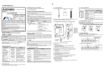
1
Side ENGLISH 1. Outline The FX3U-USB-BD (hereinafter called USB-BD) is an expansion board equipped with an USB port (MINI B plug, female) for USB communication. By connecting the USB-BD and a personal computer with USB ports, program transfer to a PLC main unit and monitoring can be performed. 1.1 Incorporated Items FX3U-USB-BD USER'S MANUAL JY997D13501 Revision F Date May 2008 USB communication expansion board FX3U-USB-BD 1 Included items M3 tapping screws USB driver software (CD-ROM) USB cable (3m (118.1")) User's Manual (this manual) 2 1 1 1 This manual describes the part names, dimensions, mounting, and specifications of the product. Before use, read this manual and the manuals of all relevant products fully to acquire proficiency in handling and operating the product. Make sure to learn all the product information, safety information, and precautions. Store this manual in a safe place so that it can be taken out and read whenever necessary. Always forward it to the end user. Registration: The company and product names described in this manual are registered trademarks or the trademarks of their respective companies. Effective May 2008 Specifications are subject to change without notice. © 2005 Mitsubishi Electric Corporation [4] SD 53.5(2.11) MASS (Weight) : 20g (0.05lbs) 19.6 (0.77) USB cable (included with the product) [9] [8] Special adapter connector cover is removed . Indicates that incorrect handling may cause hazardous conditions, resulting in death or severe injury. Indicates that incorrect handling may cause hazardous conditions, resulting in medium or slight personal injury or physical damage. Depending on the circumstances, procedures indicated by also cause severe injury. It is important to follow all precautions for personal safety. may Associated Manuals Manual name Manual No. Description FX3U Series User’s Manual - Hardware Edition JY997D16501 MODEL CODE: 09R516 Explains FX 3U Series PLC s pec i f i c ati o ns fo r I/ O , wi r i n g, installation, and maintenance. FX3UC Series User’s Manual - Hardware Edition JY997D28701 MODEL CODE: 09R519 Explains FX3UC Series PLC s pec i f i c ati o ns fo r I/ O , wi r i n g, installation, and maintenance. FX-USB-AW /FX3U-USB-BD User's Manual - USB Driver Installation Edition JY997D32601 Explains procedures for installing the USB driver software for the FXUSB-AW or FX3U-USB-BD. FX Series User’s Manual - Data Communication Edition JY997D16901 MODEL CODE: 09R715 Explains N:N network, Parallel Link, Computer Link, Non-Protocol communication by RS and RS2 instructions/FX2N-232IF. How to obtain manuals For product manuals or documents, consult with the Mitsubishi Electric dealer from who you purchased your product. P STO 3) [1] Mounting holes (2-φ3.2) [2] RD LED:Lighting while receiving data. (LED color: red) [3] SD LED:Lighting while sending data. (LED color: red) [4] USB Connector MINI B plug female [5] Main unit connector SW D5C-GPPW-E (GX Developer), FX-PCS/WIN-E *2 Use the USB driver for Windows Vista® from the USB driver software Ver.1.10. 2) 4) Make sure the expansion board (fig. B) is in parallel with the main unit (fig. C) and attach it to the expansion board connector. 5) Fix the expansion board (fig. B) to the main unit using the provided M3 tapping screws (fig. D). Tighten to a torque of 0.3 to 0.6 N⋅m IN 10 C T OU *3 GX Developer Ver. 8.23Z or later is applicable to the FX3U Series PLC. Its Ver. 8.13P or later is applicable to the FX3UC-32MT-LT Series PLC. For further details concerning alternative inapplicable programming tool setting, refer to the following manual. → Refer to the FX3U Series User's Manual - Hardware Edition → Refer to the FX3UC Series User's Manual - Hardware Edition FX3U-48M /ES MR -48 -48M FX3U 3U FX 4. System Configuration Connected equipment and connected cable N RU P STO 5) D [7] Software *3 *1 The USB driver for Windows® 98, Windows® 98SE, Windows® Millennium Edition, Windows® 2000 and Windows ® XP included in the USB driver software Ver. 1.10 is used. This USB driver is the same driver as the USB driver for software previous to Ver.1.10. N RU RD - PLC - FX3U-USB-BD [6] Special adapter connector cover [7] Special adapter connector [8] USB Connector (To FX3U -USB-BD) MINI B plug male [9] USB Connector (To personal computer) A plug male 2. Installation INSTALLATION PRECAUTIONS • Make sure to cut off all phases of the power supply externally before attempting installation or wiring work. Failure to do so may cause electric shock or damage to the product. INSTALLATION PRECAUTIONS • Use the product within the generic environment specifications described in PLC main unit manual (Hardware Edition). Never use the product in areas with excessive dust, oily smoke, conductive dusts, corrosive gas (salt air, Cl 2 , H 2 S, SO 2 or NO 2 ), flammable gas, vibration or impacts, or exposed to high temperature, condensation, or rain and wind. If the product is used in such conditions, electric shock, fire, malfunctions, deterioration or damage may occur. • Use screwdrivers carefully when performing installation work, thus avoiding accident or product damage. • When drilling screw holes or wiring, make sure cutting or wire debris does not enter the ventilation slits. Failure to do so may cause fire, equipment failures or malfunctions. • Do not touch the conductive parts of the product directly. Doing so may cause device failures or malfunctions. • Connect expansion board securely to their designated connectors. Loose connections may cause malfunctions. Applicable standards FX 3U-USB-BD units made in June, 2005 or later comply with the EC Directive (EMC Directive). Further information can be found in the following manual. However, the FX 3UC-32MT-LT does not comply with the EC Directive (EMC Directive). → Refer to the FX 3U Series Hardware Manual (Manual No. JY997D18801) USB driver software Personal computer Install B 4) D 3. Specifications This manual classifies the safety precautions into two categories: and /ES MR -48M FX3U-48 A [5] [3] OS 1 FX3U-48M 3U FX [2] B Safety Precaution (Read these precautions before use.) [6] T 10 OU Unit:mm (inches) [1] Specification Microsoft® Windows ® 98*1, Windows® 98SE*1 Microsoft® Windows ® Millennium Edition (Windows® Me)*1 Microsoft® Windows ® 2000*1 Microsoft® Windows ® XP*1 Microsoft® Windows Vista®*2 0 11 IN 10 3) Remove the dummy expansion board cover (fig. A) perpendicularly away from the main unit. 1.2 External Dimensions and Part Names 46.1(1.81) Manual Number Product Item 2.1 Installation Method 1) Power off the PLC. Disconnect all the cables connected to the PLC. Demount the PLC from the DIN rail. 2) Using a flat head screwdriver as shown in the figure on the right, lift the dummy expansion board cover (fig. A) making sure not to damage the circuit board or electronic parts. Verify that the following product and items are included in the package: 3.5 System Requirements The following section describes the installation method for the FX3U /FX3UC -32MT-LT Series PLC (FX3U Series PLC is used for the following example). For more details on installation and removal, refer to the PLC main unit manual. → Refer to the FX3U Series User's Manual - Hardware Edition → Refer to the FX3UC Series User's Manual - Hardware Edition USB cable for personal computer connection (included with the product) 3.1 Applicable PLC Model name USB port Applicability B B JAPANESE 2 A 1 Side 0 B JY997D13501F 0 Side FX 3U Series PLC Ver.2.20 or later (from first production) FX 3UC-32MT-LT Ver.1.00 or later (from first production) For details of the programming communication, refer to the following manual. → Refer to the FX Series User's Manual - Data Communication Edition • The expansion board cannot be connected to FX3UC Series PLCs other than the FX3UC-32MT-LT. • Only one expansion board can be used per main unit. additional expansion boards such as the FX3U -232-BD, FX3U -422-BD or FX3U-485BD cannot be installed/used together with the FX3U -USB-BD. For details on the system configuration, refer to the following manual. → Refer to the FX Series User's Manual - Data Communication Edition 3.2 General Specifications The general specifications are equivalent to the PLC main unit. For general specifications, refer to the following manuals. However, please do not perform any dielectric withstand voltage tests or insulation resistance tests to this product. → Refer to the FX3U Series User's Manual - Hardware Edition → Refer to the FX3UC Series User's Manual - Hardware Edition 3.3 Power Supply Specification Item Current consumption Specification • 15mA / DC 5V (5V DC power is supplied from the main unit) • 30mA / DC 5V (5V DC power is supplied from the USB connector of personal computer) 3.4 Communication Specifications Item Specification 5. Connecting Procedure 1) Power off the PLC. 2) Connect the USB (MINI B plug male) connector of the USB cable to the FX 3U-USB-BD. 3) Connect the USB (A plug male) connector of the USB cable to the personal computer. 4) Turn ON the power supply of the PLC. 5) Turn ON the power supply of the personal computer. 6. Driver Installation When the USB cable is connected to the personal computer, the Found New Hardware Wizard screen is displayed. Install USB driver software from the included CD-ROM. Caution The driver is not installed properly when canceled during the installation. To complete the installation, uninstall the driver, and install again. For the uninstallation procedure of the driver, refer to the following manual. → FX-USB-AW/FX3U-USB-BD User's Manual - USB Driver Installation Edition Note: This product requires USB Driver Installation for each USB port to be connected. To use multiple USB ports, connect this product to each port, and install the driver individually. (With Windows Vista®, Driver installation will occur automatically. In other OS, depending on the PC environment, Driver installation may occur automatically.) USB driver software folder structure The folder structure is as follows according to the USB driver software version. Transmission standard USB2.0 (For full speed) Isolation Photocoupler isolation (Between communication line and CPU) Maximum transmission distance 5m (196.9") at most (Included cable is 3m (118.1").) Baud Rate 9600/19200/38400/57600/115200 bps Port USB (MINI B plug female) Ver. 1.10 or higher <CD-ROM Drive> <WinXP_2000_ME_98> The USB driver for Windows® 98, Windows® 98SE, Windows® Millennium Edition (Me), Windows® 2000 and Windows® XP is stored. <WinVista> The USB driver for Windows Vista® is stored. Versions previous to Ver. 1.10 The USB driver for software previous to Ver. 1.10 does not have a folder structure. The USB driver is stored in the main directory of the CD-ROM drive. 6.1 Windows ® 98, Windows® 98SE, Windows ® Millennium Edition, Windows® 2000, and Windows® XP 4) The following screen is displayed. Please install the driver by the following procedure. The installation procedure is explained when connecting to a personal computer with Windows ® XP. • Windows ® 98, Windows® 98SE, Windows® Millennium Edition, and Windows® 2000, the installation method will vary. B) 1) When the USB cable is connected to the personal computer, the following screen is displayed. A) Click [ Next > ]. The installation of the USB Serial Port software will begin. - If using Windows® 2000, a screen to select the location of the installation files is displayed. Please select the CD-ROM drive. 5) The screen of 2) is displayed. (Only in Windows® XP) Click [ Continue Anyway ]. 6) The following screen is displayed. Insert the included CD-ROM into the personal computer's CD-ROM drive. Click [ Next > ]. The installation of the USB driver software will begin. - If using Windows® 98 and Windows® 98SE A window to select the location of the installation files will appear. Specify the USB driver software version as follows: Check following: - FX-USB-AW/FX3U-USB-BD is indicated at A). - FX-USB-AW/FX3U-USB-BD (COM *) is indicated at B). * indicates the COM number used in FX3U-USB-BD. - Install the driver again when is displayed. Select the programming software COM number as the COM number currently assigned on the screen above. Setting GX Developer: Double-click [ Online ] → [ Transfer setup ] → [ Serial ] of personal computer side I/F. Select the same COM number as the COM number of the personal computer when the personal computer side I/F serial setting Dialog Box appears. Click [ OK ] of [ Connection Setup ] screen to end. • The expansion board cannot be connected to FX3UC Series PLC other than FX3UC-32MT-LT. • Only one expansion board can be used per main unit. Additional expansion boards such as the FX 3U -232-BD, FX 3U -422-BD or FX3U-485-BD cannot be installed/used together with the FX3U-USB-BD. • FX3U-USB-BD and a personal computer are connected and the PLC is turned on, and then an operations such as write, read, and monitor are tried for the first time using a programming tool, a communication error message may be displayed. In such a case, clear the message and try the operations again. • If a communication error message is indicated while operating the programming tool (when executing 'Write to PLC', 'Read from PLC', or 'Monitor'), disconnect the USB cable once (from either the personal computer or the FX3U-USB-BD) and connect it again. Then clear the error message and choose Write, Read, or Monitor again. • The programming tool may not be operated properly due to a contact failure at connectors or wire breakage. Make sure to save the program before transferring or changing it. 10. Troubleshooting • If communication cannot be established between the PLC and a personal computer using FX3U -USB-BD, confirm the following status by checking SD LED and RD LED in FX3U -USB-BD. The status of SD LED and RD RED The status of SD LED and RD LED. Blinking SD Ver. 1.10 or higher Please select the "Include this location in the search", and install by specifying the "\WinXP_2000_ME_98" directory from the CD-ROM drive. Blinking Versions previous to Ver. 1.10 Please select the CD-ROM drive. - If using Windows® Millennium Edition, and Windows® 2000 A window to select the location of the installation files will appear. Please select the CD-ROM drive. 8. Uninstalling Driver For the uninstallation procedure of the driver, refer to the following manual. → FX-USB-AW/FX 3U-USB-BD User's Manual - USB Driver Installation Edition 2) The following screen is displayed. (Only in Windows® XP) 9. Caution on use Click [ Finish ]. The installation of the USB Serial Port software will finish. The CD-ROM (USB driver software) can be removed from the personal computer at this time. 6.2 Windows Vista® For the installation procedure of the driver, refer to the following manual. → FX-USB-AW/FX 3U-USB-BD User's Manual - USB Driver Installation Edition 7. Installation Confirmation of Driver Click [ Continue Anyway ]. 3) The following screen is displayed. Procedure for confirming the installation of the driver is described below. Windows® XP example follows. • In Windows® XP, click [ Start ] → [ Control Panel ] → [ Performance and Maintenance ] → [ System ] → [ Hardware ] → [ Device Manager ] and the window below will be displayed. Please confirm the COM number to which the driver is allocated (COM and LPT). • If using Windows® 98, Windows® 98SE, Windows® Millennium Edition or Windows® 2000 A screen that is equivalent to the one below is displayed by clicking [ My Computer ] → [ Control Panel ] → [ System ] → [ Device Manager ] in the menu of the personal computer. • If using Windows Vista® A screen that is equivalent to the one below is displayed by clicking [ Start ] → [ Control Panel ] → [ Hardware and Sound ] → [ Device Manager ] in the menu of the personal computer. When user account control is enabled Only when user account control is enabled will the "user account control" screen be displayed. Click [ Continue ], when displayed. Click [ Finish ]. If using Windows® 2000 or Windows® XP, proceed to step 4). - If Windows ® 98, Windows® 98SE or Windows® Millennium Edition is used, installation of the USB Serial Port software begins, and ends automatically. The CD-ROM can be removed from the personal computer at this time. The installation of the USB driver software is finished. Extinguished STARTUP AND MAINTENANCE PRECAUTIONS • Before a program or setting on-line or off-line change is performed, please read all relevant manuals and confirm safety aspects. Incorrect operation may damage the product or cause an accident. RD Extinguished Contents Communicating correctly • Confirm that the power is supplied to the personal computer. • Confirm the personal computer and the PLC are connected properly with the specified cable. • Confirm that the communication settings and connected PLC are correctly set in the software. Refer to the software manual. Data receiving • Confirm that the power is supplied to PLC. • The PLC will not operate when a configuration that exceeds the DC 5V or DC 24V capacity is used. It will also be impossible to communicate normally. • Confirm that the specified cable is used to connect the personal computer and PLC. • Confirm that the communication settings and connected PLC are correctly set in the software. Refer to the software manual. • When driver installation is required after already establishing USB communication. → This product requires USB Driver Installation for each USB port to be connected. Connect the product to a driver-installed USB port, or install the driver to the current port. STARTUP AND MAINTENANCE PRECAUTIONS • Do not disassemble or modify the unit. Doing so may cause failure, malfunction or fire. * For repair, contact your local Mitsubishi Electric distributor. • Do not drop the product or do not exert strong impact, doing so may cause damage. DISPOSAL PRECAUTIONS • Please contact a company certified in the disposal of electronic waste for environmentally safe recycling and disposal of the product. TRANSPORT AND STORAGE PRECAUTIONS • During transportation avoid any impact as the product is a precision instrument. Check the operation of the product after transportation. This manual confers no industrial property rights or any rights of any other kind, nor does it confer any patent licenses. Mitsubishi Electric Corporation cannot be held responsible for any problems involving industrial property rights which may occur as a result of using the contents noted in this manual. Warranty Mitsubishi will not be held liable for damage caused by factors found not to be the cause of Mitsubishi; opportunity loss or lost profits caused by faults in the Mitsubishi products; damage, secondary damage, accident compensation caused by special factors unpredictable by Mitsubishi; damages to products other than Mitsubishi products; and to other duties. For safe use • This product has been manufactured as a general-purpose part for general industries, and has not been designed or manufactured to be incorporated in a device or system used in purposes related to human life. • Before using the product for special purposes such as nuclear power, electric power, aerospace, medicine or passenger movement vehicles, consult with Mitsubishi Electric. • This product has been manufactured under strict quality control. However when installing the product where major accidents or losses could occur if the product fails, install appropriate backup or failsafe functions in the system. HEAD OFFICE : TOKYO BUILDING, 2-7-3 MARUNOUCHI, CHIYODA-KU, TOKYO 100-8310, JAPAN HIMEJI WORKS : 840, CHIYODA CHO, HIMEJI, JAPAN Side ENGLISH 1. Outline The FX3U-USB-BD (hereinafter called USB-BD) is an expansion board equipped with an USB port (MINI B plug, female) for USB communication. By connecting the USB-BD and a personal computer with USB ports, program transfer to a PLC main unit and monitoring can be performed. 1.1 Incorporated Items FX3U-USB-BD USER'S MANUAL JY997D13501 Revision F Date May 2008 USB communication expansion board FX3U-USB-BD 1 Included items M3 tapping screws USB driver software (CD-ROM) USB cable (3m (118.1")) User's Manual (this manual) 2 1 1 1 This manual describes the part names, dimensions, mounting, and specifications of the product. Before use, read this manual and the manuals of all relevant products fully to acquire proficiency in handling and operating the product. Make sure to learn all the product information, safety information, and precautions. Store this manual in a safe place so that it can be taken out and read whenever necessary. Always forward it to the end user. Registration: The company and product names described in this manual are registered trademarks or the trademarks of their respective companies. Effective May 2008 Specifications are subject to change without notice. © 2005 Mitsubishi Electric Corporation [4] SD 53.5(2.11) MASS (Weight) : 20g (0.05lbs) 19.6 (0.77) USB cable (included with the product) [9] [8] Special adapter connector cover is removed . Indicates that incorrect handling may cause hazardous conditions, resulting in death or severe injury. Indicates that incorrect handling may cause hazardous conditions, resulting in medium or slight personal injury or physical damage. Depending on the circumstances, procedures indicated by also cause severe injury. It is important to follow all precautions for personal safety. may Associated Manuals Manual name Manual No. Description FX3U Series User’s Manual - Hardware Edition JY997D16501 MODEL CODE: 09R516 Explains FX 3U Series PLC s pec i f i c ati o ns fo r I/ O , wi r i n g, installation, and maintenance. FX3UC Series User’s Manual - Hardware Edition JY997D28701 MODEL CODE: 09R519 Explains FX3UC Series PLC s pec i f i c ati o ns fo r I/ O , wi r i n g, installation, and maintenance. FX-USB-AW /FX3U-USB-BD User's Manual - USB Driver Installation Edition JY997D32601 Explains procedures for installing the USB driver software for the FXUSB-AW or FX3U-USB-BD. FX Series User’s Manual - Data Communication Edition JY997D16901 MODEL CODE: 09R715 Explains N:N network, Parallel Link, Computer Link, Non-Protocol communication by RS and RS2 instructions/FX2N-232IF. How to obtain manuals For product manuals or documents, consult with the Mitsubishi Electric dealer from who you purchased your product. P STO 3) [1] Mounting holes (2-φ3.2) [2] RD LED:Lighting while receiving data. (LED color: red) [3] SD LED:Lighting while sending data. (LED color: red) [4] USB Connector MINI B plug female [5] Main unit connector SW D5C-GPPW-E (GX Developer), FX-PCS/WIN-E *2 Use the USB driver for Windows Vista® from the USB driver software Ver.1.10. 2) 4) Make sure the expansion board (fig. B) is in parallel with the main unit (fig. C) and attach it to the expansion board connector. 5) Fix the expansion board (fig. B) to the main unit using the provided M3 tapping screws (fig. D). Tighten to a torque of 0.3 to 0.6 N⋅m IN 10 C T OU *3 GX Developer Ver. 8.23Z or later is applicable to the FX3U Series PLC. Its Ver. 8.13P or later is applicable to the FX3UC-32MT-LT Series PLC. For further details concerning alternative inapplicable programming tool setting, refer to the following manual. → Refer to the FX3U Series User's Manual - Hardware Edition → Refer to the FX3UC Series User's Manual - Hardware Edition FX3U-48M /ES MR -48 -48M FX3U 3U FX 4. System Configuration Connected equipment and connected cable N RU P STO 5) D [7] Software *3 *1 The USB driver for Windows® 98, Windows® 98SE, Windows® Millennium Edition, Windows® 2000 and Windows ® XP included in the USB driver software Ver. 1.10 is used. This USB driver is the same driver as the USB driver for software previous to Ver.1.10. N RU RD - PLC - FX3U-USB-BD [6] Special adapter connector cover [7] Special adapter connector [8] USB Connector (To FX3U -USB-BD) MINI B plug male [9] USB Connector (To personal computer) A plug male 2. Installation INSTALLATION PRECAUTIONS • Make sure to cut off all phases of the power supply externally before attempting installation or wiring work. Failure to do so may cause electric shock or damage to the product. INSTALLATION PRECAUTIONS • Use the product within the generic environment specifications described in PLC main unit manual (Hardware Edition). Never use the product in areas with excessive dust, oily smoke, conductive dusts, corrosive gas (salt air, Cl 2 , H 2 S, SO 2 or NO 2 ), flammable gas, vibration or impacts, or exposed to high temperature, condensation, or rain and wind. If the product is used in such conditions, electric shock, fire, malfunctions, deterioration or damage may occur. • Use screwdrivers carefully when performing installation work, thus avoiding accident or product damage. • When drilling screw holes or wiring, make sure cutting or wire debris does not enter the ventilation slits. Failure to do so may cause fire, equipment failures or malfunctions. • Do not touch the conductive parts of the product directly. Doing so may cause device failures or malfunctions. • Connect expansion board securely to their designated connectors. Loose connections may cause malfunctions. Applicable standards FX 3U-USB-BD units made in June, 2005 or later comply with the EC Directive (EMC Directive). Further information can be found in the following manual. However, the FX 3UC-32MT-LT does not comply with the EC Directive (EMC Directive). → Refer to the FX 3U Series Hardware Manual (Manual No. JY997D18801) USB driver software Personal computer Install B 4) D 3. Specifications This manual classifies the safety precautions into two categories: and /ES MR -48M FX3U-48 A [5] [3] OS 1 FX3U-48M 3U FX [2] B Safety Precaution (Read these precautions before use.) [6] T 10 OU Unit:mm (inches) [1] Specification Microsoft® Windows ® 98*1, Windows® 98SE*1 Microsoft® Windows ® Millennium Edition (Windows® Me)*1 Microsoft® Windows ® 2000*1 Microsoft® Windows ® XP*1 Microsoft® Windows Vista®*2 0 11 IN 10 3) Remove the dummy expansion board cover (fig. A) perpendicularly away from the main unit. 1.2 External Dimensions and Part Names 46.1(1.81) Manual Number Product Item 2.1 Installation Method 1) Power off the PLC. Disconnect all the cables connected to the PLC. Demount the PLC from the DIN rail. 2) Using a flat head screwdriver as shown in the figure on the right, lift the dummy expansion board cover (fig. A) making sure not to damage the circuit board or electronic parts. Verify that the following product and items are included in the package: 3.5 System Requirements The following section describes the installation method for the FX3U /FX3UC -32MT-LT Series PLC (FX3U Series PLC is used for the following example). For more details on installation and removal, refer to the PLC main unit manual. → Refer to the FX3U Series User's Manual - Hardware Edition → Refer to the FX3UC Series User's Manual - Hardware Edition USB cable for personal computer connection (included with the product) 3.1 Applicable PLC Model name USB port Applicability B B JAPANESE 2 A 1 Side 0 B JY997D13501F 0 Side FX 3U Series PLC Ver.2.20 or later (from first production) FX 3UC-32MT-LT Ver.1.00 or later (from first production) For details of the programming communication, refer to the following manual. → Refer to the FX Series User's Manual - Data Communication Edition • The expansion board cannot be connected to FX3UC Series PLCs other than the FX3UC-32MT-LT. • Only one expansion board can be used per main unit. additional expansion boards such as the FX3U -232-BD, FX3U -422-BD or FX3U-485BD cannot be installed/used together with the FX3U -USB-BD. For details on the system configuration, refer to the following manual. → Refer to the FX Series User's Manual - Data Communication Edition 3.2 General Specifications The general specifications are equivalent to the PLC main unit. For general specifications, refer to the following manuals. However, please do not perform any dielectric withstand voltage tests or insulation resistance tests to this product. → Refer to the FX3U Series User's Manual - Hardware Edition → Refer to the FX3UC Series User's Manual - Hardware Edition 3.3 Power Supply Specification Item Current consumption Specification • 15mA / DC 5V (5V DC power is supplied from the main unit) • 30mA / DC 5V (5V DC power is supplied from the USB connector of personal computer) 3.4 Communication Specifications Item Specification 5. Connecting Procedure 1) Power off the PLC. 2) Connect the USB (MINI B plug male) connector of the USB cable to the FX 3U-USB-BD. 3) Connect the USB (A plug male) connector of the USB cable to the personal computer. 4) Turn ON the power supply of the PLC. 5) Turn ON the power supply of the personal computer. 6. Driver Installation When the USB cable is connected to the personal computer, the Found New Hardware Wizard screen is displayed. Install USB driver software from the included CD-ROM. Caution The driver is not installed properly when canceled during the installation. To complete the installation, uninstall the driver, and install again. For the uninstallation procedure of the driver, refer to the following manual. → FX-USB-AW/FX3U-USB-BD User's Manual - USB Driver Installation Edition Note: This product requires USB Driver Installation for each USB port to be connected. To use multiple USB ports, connect this product to each port, and install the driver individually. (With Windows Vista®, Driver installation will occur automatically. In other OS, depending on the PC environment, Driver installation may occur automatically.) USB driver software folder structure The folder structure is as follows according to the USB driver software version. Transmission standard USB2.0 (For full speed) Isolation Photocoupler isolation (Between communication line and CPU) Maximum transmission distance 5m (196.9") at most (Included cable is 3m (118.1").) Baud Rate 9600/19200/38400/57600/115200 bps Port USB (MINI B plug female) Ver. 1.10 or higher <CD-ROM Drive> <WinXP_2000_ME_98> The USB driver for Windows® 98, Windows® 98SE, Windows® Millennium Edition (Me), Windows® 2000 and Windows® XP is stored. <WinVista> The USB driver for Windows Vista® is stored. Versions previous to Ver. 1.10 The USB driver for software previous to Ver. 1.10 does not have a folder structure. The USB driver is stored in the main directory of the CD-ROM drive. 6.1 Windows ® 98, Windows® 98SE, Windows ® Millennium Edition, Windows® 2000, and Windows® XP 4) The following screen is displayed. Please install the driver by the following procedure. The installation procedure is explained when connecting to a personal computer with Windows ® XP. • Windows ® 98, Windows® 98SE, Windows® Millennium Edition, and Windows® 2000, the installation method will vary. B) 1) When the USB cable is connected to the personal computer, the following screen is displayed. A) Click [ Next > ]. The installation of the USB Serial Port software will begin. - If using Windows® 2000, a screen to select the location of the installation files is displayed. Please select the CD-ROM drive. 5) The screen of 2) is displayed. (Only in Windows® XP) Click [ Continue Anyway ]. 6) The following screen is displayed. Insert the included CD-ROM into the personal computer's CD-ROM drive. Click [ Next > ]. The installation of the USB driver software will begin. - If using Windows® 98 and Windows® 98SE A window to select the location of the installation files will appear. Specify the USB driver software version as follows: Check following: - FX-USB-AW/FX3U-USB-BD is indicated at A). - FX-USB-AW/FX3U-USB-BD (COM *) is indicated at B). * indicates the COM number used in FX3U-USB-BD. - Install the driver again when is displayed. Select the programming software COM number as the COM number currently assigned on the screen above. Setting GX Developer: Double-click [ Online ] → [ Transfer setup ] → [ Serial ] of personal computer side I/F. Select the same COM number as the COM number of the personal computer when the personal computer side I/F serial setting Dialog Box appears. Click [ OK ] of [ Connection Setup ] screen to end. • The expansion board cannot be connected to FX3UC Series PLC other than FX3UC-32MT-LT. • Only one expansion board can be used per main unit. Additional expansion boards such as the FX 3U -232-BD, FX 3U -422-BD or FX3U-485-BD cannot be installed/used together with the FX3U-USB-BD. • FX3U-USB-BD and a personal computer are connected and the PLC is turned on, and then an operations such as write, read, and monitor are tried for the first time using a programming tool, a communication error message may be displayed. In such a case, clear the message and try the operations again. • If a communication error message is indicated while operating the programming tool (when executing 'Write to PLC', 'Read from PLC', or 'Monitor'), disconnect the USB cable once (from either the personal computer or the FX3U-USB-BD) and connect it again. Then clear the error message and choose Write, Read, or Monitor again. • The programming tool may not be operated properly due to a contact failure at connectors or wire breakage. Make sure to save the program before transferring or changing it. 10. Troubleshooting • If communication cannot be established between the PLC and a personal computer using FX3U -USB-BD, confirm the following status by checking SD LED and RD LED in FX3U -USB-BD. The status of SD LED and RD RED The status of SD LED and RD LED. Blinking SD Ver. 1.10 or higher Please select the "Include this location in the search", and install by specifying the "\WinXP_2000_ME_98" directory from the CD-ROM drive. Blinking Versions previous to Ver. 1.10 Please select the CD-ROM drive. - If using Windows® Millennium Edition, and Windows® 2000 A window to select the location of the installation files will appear. Please select the CD-ROM drive. 8. Uninstalling Driver For the uninstallation procedure of the driver, refer to the following manual. → FX-USB-AW/FX 3U-USB-BD User's Manual - USB Driver Installation Edition 2) The following screen is displayed. (Only in Windows® XP) 9. Caution on use Click [ Finish ]. The installation of the USB Serial Port software will finish. The CD-ROM (USB driver software) can be removed from the personal computer at this time. 6.2 Windows Vista® For the installation procedure of the driver, refer to the following manual. → FX-USB-AW/FX 3U-USB-BD User's Manual - USB Driver Installation Edition 7. Installation Confirmation of Driver Click [ Continue Anyway ]. 3) The following screen is displayed. Procedure for confirming the installation of the driver is described below. Windows® XP example follows. • In Windows® XP, click [ Start ] → [ Control Panel ] → [ Performance and Maintenance ] → [ System ] → [ Hardware ] → [ Device Manager ] and the window below will be displayed. Please confirm the COM number to which the driver is allocated (COM and LPT). • If using Windows® 98, Windows® 98SE, Windows® Millennium Edition or Windows® 2000 A screen that is equivalent to the one below is displayed by clicking [ My Computer ] → [ Control Panel ] → [ System ] → [ Device Manager ] in the menu of the personal computer. • If using Windows Vista® A screen that is equivalent to the one below is displayed by clicking [ Start ] → [ Control Panel ] → [ Hardware and Sound ] → [ Device Manager ] in the menu of the personal computer. When user account control is enabled Only when user account control is enabled will the "user account control" screen be displayed. Click [ Continue ], when displayed. Click [ Finish ]. If using Windows® 2000 or Windows® XP, proceed to step 4). - If Windows ® 98, Windows® 98SE or Windows® Millennium Edition is used, installation of the USB Serial Port software begins, and ends automatically. The CD-ROM can be removed from the personal computer at this time. The installation of the USB driver software is finished. Extinguished STARTUP AND MAINTENANCE PRECAUTIONS • Before a program or setting on-line or off-line change is performed, please read all relevant manuals and confirm safety aspects. Incorrect operation may damage the product or cause an accident. RD Extinguished Contents Communicating correctly • Confirm that the power is supplied to the personal computer. • Confirm the personal computer and the PLC are connected properly with the specified cable. • Confirm that the communication settings and connected PLC are correctly set in the software. Refer to the software manual. Data receiving • Confirm that the power is supplied to PLC. • The PLC will not operate when a configuration that exceeds the DC 5V or DC 24V capacity is used. It will also be impossible to communicate normally. • Confirm that the specified cable is used to connect the personal computer and PLC. • Confirm that the communication settings and connected PLC are correctly set in the software. Refer to the software manual. • When driver installation is required after already establishing USB communication. → This product requires USB Driver Installation for each USB port to be connected. Connect the product to a driver-installed USB port, or install the driver to the current port. STARTUP AND MAINTENANCE PRECAUTIONS • Do not disassemble or modify the unit. Doing so may cause failure, malfunction or fire. * For repair, contact your local Mitsubishi Electric distributor. • Do not drop the product or do not exert strong impact, doing so may cause damage. DISPOSAL PRECAUTIONS • Please contact a company certified in the disposal of electronic waste for environmentally safe recycling and disposal of the product. TRANSPORT AND STORAGE PRECAUTIONS • During transportation avoid any impact as the product is a precision instrument. Check the operation of the product after transportation. This manual confers no industrial property rights or any rights of any other kind, nor does it confer any patent licenses. Mitsubishi Electric Corporation cannot be held responsible for any problems involving industrial property rights which may occur as a result of using the contents noted in this manual. Warranty Mitsubishi will not be held liable for damage caused by factors found not to be the cause of Mitsubishi; opportunity loss or lost profits caused by faults in the Mitsubishi products; damage, secondary damage, accident compensation caused by special factors unpredictable by Mitsubishi; damages to products other than Mitsubishi products; and to other duties. For safe use • This product has been manufactured as a general-purpose part for general industries, and has not been designed or manufactured to be incorporated in a device or system used in purposes related to human life. • Before using the product for special purposes such as nuclear power, electric power, aerospace, medicine or passenger movement vehicles, consult with Mitsubishi Electric. • This product has been manufactured under strict quality control. However when installing the product where major accidents or losses could occur if the product fails, install appropriate backup or failsafe functions in the system. HEAD OFFICE : TOKYO BUILDING, 2-7-3 MARUNOUCHI, CHIYODA-KU, TOKYO 100-8310, JAPAN HIMEJI WORKS : 840, CHIYODA CHO, HIMEJI, JAPAN Side ENGLISH 1. Outline The FX3U-USB-BD (hereinafter called USB-BD) is an expansion board equipped with an USB port (MINI B plug, female) for USB communication. By connecting the USB-BD and a personal computer with USB ports, program transfer to a PLC main unit and monitoring can be performed. 1.1 Incorporated Items FX3U-USB-BD USER'S MANUAL JY997D13501 Revision F Date May 2008 USB communication expansion board FX3U-USB-BD 1 Included items M3 tapping screws USB driver software (CD-ROM) USB cable (3m (118.1")) User's Manual (this manual) 2 1 1 1 This manual describes the part names, dimensions, mounting, and specifications of the product. Before use, read this manual and the manuals of all relevant products fully to acquire proficiency in handling and operating the product. Make sure to learn all the product information, safety information, and precautions. Store this manual in a safe place so that it can be taken out and read whenever necessary. Always forward it to the end user. Registration: The company and product names described in this manual are registered trademarks or the trademarks of their respective companies. Effective May 2008 Specifications are subject to change without notice. © 2005 Mitsubishi Electric Corporation [4] SD 53.5(2.11) MASS (Weight) : 20g (0.05lbs) 19.6 (0.77) USB cable (included with the product) [9] [8] Special adapter connector cover is removed . Indicates that incorrect handling may cause hazardous conditions, resulting in death or severe injury. Indicates that incorrect handling may cause hazardous conditions, resulting in medium or slight personal injury or physical damage. Depending on the circumstances, procedures indicated by also cause severe injury. It is important to follow all precautions for personal safety. may Associated Manuals Manual name Manual No. Description FX3U Series User’s Manual - Hardware Edition JY997D16501 MODEL CODE: 09R516 Explains FX 3U Series PLC s pec i f i c ati o ns fo r I/ O , wi r i n g, installation, and maintenance. FX3UC Series User’s Manual - Hardware Edition JY997D28701 MODEL CODE: 09R519 Explains FX3UC Series PLC s pec i f i c ati o ns fo r I/ O , wi r i n g, installation, and maintenance. FX-USB-AW /FX3U-USB-BD User's Manual - USB Driver Installation Edition JY997D32601 Explains procedures for installing the USB driver software for the FXUSB-AW or FX3U-USB-BD. FX Series User’s Manual - Data Communication Edition JY997D16901 MODEL CODE: 09R715 Explains N:N network, Parallel Link, Computer Link, Non-Protocol communication by RS and RS2 instructions/FX2N-232IF. How to obtain manuals For product manuals or documents, consult with the Mitsubishi Electric dealer from who you purchased your product. P STO 3) [1] Mounting holes (2-φ3.2) [2] RD LED:Lighting while receiving data. (LED color: red) [3] SD LED:Lighting while sending data. (LED color: red) [4] USB Connector MINI B plug female [5] Main unit connector SW D5C-GPPW-E (GX Developer), FX-PCS/WIN-E *2 Use the USB driver for Windows Vista® from the USB driver software Ver.1.10. 2) 4) Make sure the expansion board (fig. B) is in parallel with the main unit (fig. C) and attach it to the expansion board connector. 5) Fix the expansion board (fig. B) to the main unit using the provided M3 tapping screws (fig. D). Tighten to a torque of 0.3 to 0.6 N⋅m IN 10 C T OU *3 GX Developer Ver. 8.23Z or later is applicable to the FX3U Series PLC. Its Ver. 8.13P or later is applicable to the FX3UC-32MT-LT Series PLC. For further details concerning alternative inapplicable programming tool setting, refer to the following manual. → Refer to the FX3U Series User's Manual - Hardware Edition → Refer to the FX3UC Series User's Manual - Hardware Edition FX3U-48M /ES MR -48 -48M FX3U 3U FX 4. System Configuration Connected equipment and connected cable N RU P STO 5) D [7] Software *3 *1 The USB driver for Windows® 98, Windows® 98SE, Windows® Millennium Edition, Windows® 2000 and Windows ® XP included in the USB driver software Ver. 1.10 is used. This USB driver is the same driver as the USB driver for software previous to Ver.1.10. N RU RD - PLC - FX3U-USB-BD [6] Special adapter connector cover [7] Special adapter connector [8] USB Connector (To FX3U -USB-BD) MINI B plug male [9] USB Connector (To personal computer) A plug male 2. Installation INSTALLATION PRECAUTIONS • Make sure to cut off all phases of the power supply externally before attempting installation or wiring work. Failure to do so may cause electric shock or damage to the product. INSTALLATION PRECAUTIONS • Use the product within the generic environment specifications described in PLC main unit manual (Hardware Edition). Never use the product in areas with excessive dust, oily smoke, conductive dusts, corrosive gas (salt air, Cl 2 , H 2 S, SO 2 or NO 2 ), flammable gas, vibration or impacts, or exposed to high temperature, condensation, or rain and wind. If the product is used in such conditions, electric shock, fire, malfunctions, deterioration or damage may occur. • Use screwdrivers carefully when performing installation work, thus avoiding accident or product damage. • When drilling screw holes or wiring, make sure cutting or wire debris does not enter the ventilation slits. Failure to do so may cause fire, equipment failures or malfunctions. • Do not touch the conductive parts of the product directly. Doing so may cause device failures or malfunctions. • Connect expansion board securely to their designated connectors. Loose connections may cause malfunctions. Applicable standards FX 3U-USB-BD units made in June, 2005 or later comply with the EC Directive (EMC Directive). Further information can be found in the following manual. However, the FX 3UC-32MT-LT does not comply with the EC Directive (EMC Directive). → Refer to the FX 3U Series Hardware Manual (Manual No. JY997D18801) USB driver software Personal computer Install B 4) D 3. Specifications This manual classifies the safety precautions into two categories: and /ES MR -48M FX3U-48 A [5] [3] OS 1 FX3U-48M 3U FX [2] B Safety Precaution (Read these precautions before use.) [6] T 10 OU Unit:mm (inches) [1] Specification Microsoft® Windows ® 98*1, Windows® 98SE*1 Microsoft® Windows ® Millennium Edition (Windows® Me)*1 Microsoft® Windows ® 2000*1 Microsoft® Windows ® XP*1 Microsoft® Windows Vista®*2 0 11 IN 10 3) Remove the dummy expansion board cover (fig. A) perpendicularly away from the main unit. 1.2 External Dimensions and Part Names 46.1(1.81) Manual Number Product Item 2.1 Installation Method 1) Power off the PLC. Disconnect all the cables connected to the PLC. Demount the PLC from the DIN rail. 2) Using a flat head screwdriver as shown in the figure on the right, lift the dummy expansion board cover (fig. A) making sure not to damage the circuit board or electronic parts. Verify that the following product and items are included in the package: 3.5 System Requirements The following section describes the installation method for the FX3U /FX3UC -32MT-LT Series PLC (FX3U Series PLC is used for the following example). For more details on installation and removal, refer to the PLC main unit manual. → Refer to the FX3U Series User's Manual - Hardware Edition → Refer to the FX3UC Series User's Manual - Hardware Edition USB cable for personal computer connection (included with the product) 3.1 Applicable PLC Model name USB port Applicability B B JAPANESE 2 A 1 Side 0 B JY997D13501F 0 Side FX 3U Series PLC Ver.2.20 or later (from first production) FX 3UC-32MT-LT Ver.1.00 or later (from first production) For details of the programming communication, refer to the following manual. → Refer to the FX Series User's Manual - Data Communication Edition • The expansion board cannot be connected to FX3UC Series PLCs other than the FX3UC-32MT-LT. • Only one expansion board can be used per main unit. additional expansion boards such as the FX3U -232-BD, FX3U -422-BD or FX3U-485BD cannot be installed/used together with the FX3U -USB-BD. For details on the system configuration, refer to the following manual. → Refer to the FX Series User's Manual - Data Communication Edition 3.2 General Specifications The general specifications are equivalent to the PLC main unit. For general specifications, refer to the following manuals. However, please do not perform any dielectric withstand voltage tests or insulation resistance tests to this product. → Refer to the FX3U Series User's Manual - Hardware Edition → Refer to the FX3UC Series User's Manual - Hardware Edition 3.3 Power Supply Specification Item Current consumption Specification • 15mA / DC 5V (5V DC power is supplied from the main unit) • 30mA / DC 5V (5V DC power is supplied from the USB connector of personal computer) 3.4 Communication Specifications Item Specification 5. Connecting Procedure 1) Power off the PLC. 2) Connect the USB (MINI B plug male) connector of the USB cable to the FX 3U-USB-BD. 3) Connect the USB (A plug male) connector of the USB cable to the personal computer. 4) Turn ON the power supply of the PLC. 5) Turn ON the power supply of the personal computer. 6. Driver Installation When the USB cable is connected to the personal computer, the Found New Hardware Wizard screen is displayed. Install USB driver software from the included CD-ROM. Caution The driver is not installed properly when canceled during the installation. To complete the installation, uninstall the driver, and install again. For the uninstallation procedure of the driver, refer to the following manual. → FX-USB-AW/FX3U-USB-BD User's Manual - USB Driver Installation Edition Note: This product requires USB Driver Installation for each USB port to be connected. To use multiple USB ports, connect this product to each port, and install the driver individually. (With Windows Vista®, Driver installation will occur automatically. In other OS, depending on the PC environment, Driver installation may occur automatically.) USB driver software folder structure The folder structure is as follows according to the USB driver software version. Transmission standard USB2.0 (For full speed) Isolation Photocoupler isolation (Between communication line and CPU) Maximum transmission distance 5m (196.9") at most (Included cable is 3m (118.1").) Baud Rate 9600/19200/38400/57600/115200 bps Port USB (MINI B plug female) Ver. 1.10 or higher <CD-ROM Drive> <WinXP_2000_ME_98> The USB driver for Windows® 98, Windows® 98SE, Windows® Millennium Edition (Me), Windows® 2000 and Windows® XP is stored. <WinVista> The USB driver for Windows Vista® is stored. Versions previous to Ver. 1.10 The USB driver for software previous to Ver. 1.10 does not have a folder structure. The USB driver is stored in the main directory of the CD-ROM drive. 6.1 Windows ® 98, Windows® 98SE, Windows ® Millennium Edition, Windows® 2000, and Windows® XP 4) The following screen is displayed. Please install the driver by the following procedure. The installation procedure is explained when connecting to a personal computer with Windows ® XP. • Windows ® 98, Windows® 98SE, Windows® Millennium Edition, and Windows® 2000, the installation method will vary. B) 1) When the USB cable is connected to the personal computer, the following screen is displayed. A) Click [ Next > ]. The installation of the USB Serial Port software will begin. - If using Windows® 2000, a screen to select the location of the installation files is displayed. Please select the CD-ROM drive. 5) The screen of 2) is displayed. (Only in Windows® XP) Click [ Continue Anyway ]. 6) The following screen is displayed. Insert the included CD-ROM into the personal computer's CD-ROM drive. Click [ Next > ]. The installation of the USB driver software will begin. - If using Windows® 98 and Windows® 98SE A window to select the location of the installation files will appear. Specify the USB driver software version as follows: Check following: - FX-USB-AW/FX3U-USB-BD is indicated at A). - FX-USB-AW/FX3U-USB-BD (COM *) is indicated at B). * indicates the COM number used in FX3U-USB-BD. - Install the driver again when is displayed. Select the programming software COM number as the COM number currently assigned on the screen above. Setting GX Developer: Double-click [ Online ] → [ Transfer setup ] → [ Serial ] of personal computer side I/F. Select the same COM number as the COM number of the personal computer when the personal computer side I/F serial setting Dialog Box appears. Click [ OK ] of [ Connection Setup ] screen to end. • The expansion board cannot be connected to FX3UC Series PLC other than FX3UC-32MT-LT. • Only one expansion board can be used per main unit. Additional expansion boards such as the FX 3U -232-BD, FX 3U -422-BD or FX3U-485-BD cannot be installed/used together with the FX3U-USB-BD. • FX3U-USB-BD and a personal computer are connected and the PLC is turned on, and then an operations such as write, read, and monitor are tried for the first time using a programming tool, a communication error message may be displayed. In such a case, clear the message and try the operations again. • If a communication error message is indicated while operating the programming tool (when executing 'Write to PLC', 'Read from PLC', or 'Monitor'), disconnect the USB cable once (from either the personal computer or the FX3U-USB-BD) and connect it again. Then clear the error message and choose Write, Read, or Monitor again. • The programming tool may not be operated properly due to a contact failure at connectors or wire breakage. Make sure to save the program before transferring or changing it. 10. Troubleshooting • If communication cannot be established between the PLC and a personal computer using FX3U -USB-BD, confirm the following status by checking SD LED and RD LED in FX3U -USB-BD. The status of SD LED and RD RED The status of SD LED and RD LED. Blinking SD Ver. 1.10 or higher Please select the "Include this location in the search", and install by specifying the "\WinXP_2000_ME_98" directory from the CD-ROM drive. Blinking Versions previous to Ver. 1.10 Please select the CD-ROM drive. - If using Windows® Millennium Edition, and Windows® 2000 A window to select the location of the installation files will appear. Please select the CD-ROM drive. 8. Uninstalling Driver For the uninstallation procedure of the driver, refer to the following manual. → FX-USB-AW/FX 3U-USB-BD User's Manual - USB Driver Installation Edition 2) The following screen is displayed. (Only in Windows® XP) 9. Caution on use Click [ Finish ]. The installation of the USB Serial Port software will finish. The CD-ROM (USB driver software) can be removed from the personal computer at this time. 6.2 Windows Vista® For the installation procedure of the driver, refer to the following manual. → FX-USB-AW/FX 3U-USB-BD User's Manual - USB Driver Installation Edition 7. Installation Confirmation of Driver Click [ Continue Anyway ]. 3) The following screen is displayed. Procedure for confirming the installation of the driver is described below. Windows® XP example follows. • In Windows® XP, click [ Start ] → [ Control Panel ] → [ Performance and Maintenance ] → [ System ] → [ Hardware ] → [ Device Manager ] and the window below will be displayed. Please confirm the COM number to which the driver is allocated (COM and LPT). • If using Windows® 98, Windows® 98SE, Windows® Millennium Edition or Windows® 2000 A screen that is equivalent to the one below is displayed by clicking [ My Computer ] → [ Control Panel ] → [ System ] → [ Device Manager ] in the menu of the personal computer. • If using Windows Vista® A screen that is equivalent to the one below is displayed by clicking [ Start ] → [ Control Panel ] → [ Hardware and Sound ] → [ Device Manager ] in the menu of the personal computer. When user account control is enabled Only when user account control is enabled will the "user account control" screen be displayed. Click [ Continue ], when displayed. Click [ Finish ]. If using Windows® 2000 or Windows® XP, proceed to step 4). - If Windows ® 98, Windows® 98SE or Windows® Millennium Edition is used, installation of the USB Serial Port software begins, and ends automatically. The CD-ROM can be removed from the personal computer at this time. The installation of the USB driver software is finished. Extinguished STARTUP AND MAINTENANCE PRECAUTIONS • Before a program or setting on-line or off-line change is performed, please read all relevant manuals and confirm safety aspects. Incorrect operation may damage the product or cause an accident. RD Extinguished Contents Communicating correctly • Confirm that the power is supplied to the personal computer. • Confirm the personal computer and the PLC are connected properly with the specified cable. • Confirm that the communication settings and connected PLC are correctly set in the software. Refer to the software manual. Data receiving • Confirm that the power is supplied to PLC. • The PLC will not operate when a configuration that exceeds the DC 5V or DC 24V capacity is used. It will also be impossible to communicate normally. • Confirm that the specified cable is used to connect the personal computer and PLC. • Confirm that the communication settings and connected PLC are correctly set in the software. Refer to the software manual. • When driver installation is required after already establishing USB communication. → This product requires USB Driver Installation for each USB port to be connected. Connect the product to a driver-installed USB port, or install the driver to the current port. STARTUP AND MAINTENANCE PRECAUTIONS • Do not disassemble or modify the unit. Doing so may cause failure, malfunction or fire. * For repair, contact your local Mitsubishi Electric distributor. • Do not drop the product or do not exert strong impact, doing so may cause damage. DISPOSAL PRECAUTIONS • Please contact a company certified in the disposal of electronic waste for environmentally safe recycling and disposal of the product. TRANSPORT AND STORAGE PRECAUTIONS • During transportation avoid any impact as the product is a precision instrument. Check the operation of the product after transportation. This manual confers no industrial property rights or any rights of any other kind, nor does it confer any patent licenses. Mitsubishi Electric Corporation cannot be held responsible for any problems involving industrial property rights which may occur as a result of using the contents noted in this manual. Warranty Mitsubishi will not be held liable for damage caused by factors found not to be the cause of Mitsubishi; opportunity loss or lost profits caused by faults in the Mitsubishi products; damage, secondary damage, accident compensation caused by special factors unpredictable by Mitsubishi; damages to products other than Mitsubishi products; and to other duties. For safe use • This product has been manufactured as a general-purpose part for general industries, and has not been designed or manufactured to be incorporated in a device or system used in purposes related to human life. • Before using the product for special purposes such as nuclear power, electric power, aerospace, medicine or passenger movement vehicles, consult with Mitsubishi Electric. • This product has been manufactured under strict quality control. However when installing the product where major accidents or losses could occur if the product fails, install appropriate backup or failsafe functions in the system. HEAD OFFICE : TOKYO BUILDING, 2-7-3 MARUNOUCHI, CHIYODA-KU, TOKYO 100-8310, JAPAN HIMEJI WORKS : 840, CHIYODA CHO, HIMEJI, JAPAN