1
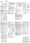
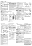
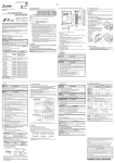
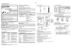
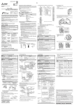
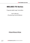
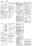
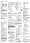
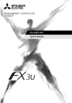
JY997D21101F Side Side A B JAPANESE ENGLISH Compliance with EC directive (CE Marking) This note does not guarantee that an entire mechanical module produced in accordance with the contents of this note will comply with the following standards. Compliance to EMC directive and LVD directive for the entire mechanical module should be checked by the user / manufacturer. For more details please contact the local Mitsubishi Electric sales site. Requirement for Compliance with EMC directive FX3U-20SSC-H INSTALLATION MANUAL Manual Number JY997D21101 Revision F Date July 2012 This manual describes the part names, dimensions, and specifications of the product. Before use, read this manual and manuals of relevant products fully to acquire proficiency in handling and operating the product. Make sure to learn all the product information, safety information, and precautions. And, store this manual in a safe place so that you can take it out and read it whenever necessary. Always forward it to the end user. Registration The company name and the product name to be described in this manual are the registered trademarks or trademarks of each company. The following products have shown compliance through direct testing (of the identified standards below) and design analysis (through the creation of a technical construction file) to the European Directive for Electromagnetic Compatibility (2004/108/EC) when used as directed by the appropriate documentation. Attention • This product is designed for use in industrial applications. Note • Manufactured by:Mitsubishi Electric Corporation 2-7-3 Marunouchi, Chiyoda-ku, Tokyo, 100-8310 Japan • Manufactured at: Mitsubishi Electric Corporation Himeji Works 840 Chiyoda-machi, Himeji, Hyogo, 670-8677 Japan • Authorized Representative in the European Community: Mitsubishi Electric Europe B.V. Gothaer Str. 8, 40880 Ratingen, Germany Type: Programmable Controller (Open Type Equipment) Models: MELSEC FX3U series manufactured from December 1st, 2005 FX3U-20SSC-H Effective July 2012 Specifications are subject to change without notice. Standard © 2005 Mitsubishi Electric Corporation Safety Precaution (Read these precautions before use.) This manual classify the safety precautions into two categories: and . Indicates that incorrect handling may cause hazardous conditions, resulting in death or severe injury. Indicates that incorrect handling may cause hazardous conditions, resulting in medium or slight personal injury or physical damage. Remark EN61131-2:2007 Compliance with all relevant aspects of the Programmable controllers standard. - Equipment requirements and EMI tests • Radiated Emission • Conducted Emission EMS • Radiated electromagnetic field • Fast transient burst • Electrostatic discharge • High-energy surge • Voltage drops and interruptions • Conducted RF • Power frequency magnetic field may also Manual No. Description FX3U Series User’s Manual - Hardware Edition JY997D16501 MODEL CODE: 09R516 Explains the FX3U Series PLC specifications for I/O, wiring, installation, and maintenance. FX3UC Series User’s Manual - Hardware Edition JY997D28701 MODEL CODE: 09R519 Explains the FX 3UC Series PLC specifications for I/O, w iring, ins tallation, and maintenance. FX3G/FX3U/FX3GC/ FX3UC Series Programming Manual - Basic & Applied Instruction Edition JY997D16601 MODEL CODE: 09R517 FX3U-20SSC-H User’s Manual JY997D21301 MODEL CODE: 09R622 D e sc ri be s FX 3 U -20 S SC -H Positioning block details. FX Configurator-FP Operation Manual JY997D21801 MODEL CODE: 09R916 Describes operation details of FX Configurator-FP Setting/ Monitoring Tool. Describes PLC programming for basic/applied instructions and devices. How to obtain manuals For product manuals or documents, contact with the Mitsubishi Electric dealer you purchased your product. Certification of UL, cUL standards The following product has UL and cUL certification. UL, cUL File Number: E95239 Models : MELSEC FX3U series manufactured from June 1st, 2006 FX3U-20SSC-H Terminal name Description Terminal name Description X-DOG Near-point DOG input terminal (for X axis) S/S Power input terminal (START, DOG, INT0 and INT1) S/S 24V DC *1 Power input terminal (START, DOG, INT0 and INT1) 24V DC *1 X-START START input terminal (for X axis) START input terminal (for Y axis) Y-DOG Y-START Near-point DOG input terminal (for Y axis) *1 Pins that have the same name (S/S) are shorted inside. Caution The pin array is seen from the connection side (aperture side) of the input connectors of the 20SSC-H. The pin numbers and the position of vary depending on the connectors for user cables. Perform wiring properly while paying attention to the position of notches and the direction of connectors. Otherwise, the product may be damaged due to wiring mistakes. 1.5.2 Power supply connector For the details on the power supply wiring and power cable, refer to the following manual. → Refer to the FX3U-20SSC-H User's Manual 200mm or less Manual name Attach the ferrite core to the power supply and input cables (20SSC-H side). Attach the ferrite core in approximately 200mm or less from connector on the 20SSC-H side. FX3U20SSC-H Associated Manuals ferrite core External equipment Input cable The ferrite core should use the following equivalent product. • Power supply cable (1 turn necessary) Model name:ZCAT2035-0930 (Manufactured by TDK co., Ltd.) • Input cable Model name:ZCAT3035-1330 (Manufactured by TDK co., Ltd.) • Make sure to have the following safety circuits outside of the PLC to ensure safe system operation even during external power supply problems or PLC failure. Otherwise, malfunctions may cause serious accidents. - Most importantly, have the following: an emergency stop circuit, a protection circuit, an interlock circuit for opposite movements (such as normal vs. reverse rotation), and an interlock circuit (to prevent damage to the equipment at the upper and lower positioning limits). - Note that when the PLC CPU detects an error, such as a watchdog timer error, during self-diagnosis, all outputs are turned off. Also, when an error that cannot be detected by the PLC CPU occurs in an input/output control block, output control may be disabled. External circuits and mechanisms should be designed to ensure safe machinery operation in such a case. - Note that when an error occurs in a relay, triac or transistor output device, the output could be held either on or off. For output signals that may lead to serious accidents, external circuits and mechanisms should be designed to ensure safe machinery operation in such a case. DESIGN PRECAUTIONS • Make sure to observe the following precautions in order to prevent any damage to the machinery or accidents due to abnormal data written to the PLC under the influence of noise. - Do not bundle the main circuit line together with or lay it close to the main circuit, high-voltage line or load line. Otherwise, noise disturbance and/or surge induction are likely to take place. As a guideline, lay the control line at least 100mm (3.94") or more away from the main circuit or high-voltage lines. - Ground the shield wire or shield of the shielded cable at one point on the PLC. However, do not ground them at the same point as the high-voltage lines. - Install module so that excessive force will not be applied to the input, power, and optical connectors. Failure to do so may result in wire damage/breakage or PLC failure. STARTUP AND MAINTENANCE PRECAUTIONS • Do not disassemble or modify the PLC. Doing so may cause fire, equipment failures, or malfunctions. For repair, contact your local Mitsubishi Electric representative. • Do not drop the product or exert strong impact to it. Doing so may cause damage. DISPOSAL PRECAUTIONS • Please contact a certified electronic waste disposal company for the environmentally safe recycling and disposal of your device. *3 The MR-J4- B can be connected within the functional range of the "J3 compatibility mode" to the 20SSC-H. 3) Easy application of absolute position detection system - The servo amplifier with absolute position detection enables the absolute positioning detection system. - Once the zero position is established, the zero return operation at power startup is not necessary. - The absolute position system allows the establishment of zero position by the data set type zero return. In this case, wiring for near-point DOG, etc. is not required. 4) Easy maintenance - Various data such as positioning data, parameters, etc. can be saved to the flash memory (ROM) in the 20SSC-H. - This allows the data to be saved without a battery. 5) Connectable PLC - The connected FX3U or FX3UC PLC reads/writes the positioning data from/to the 20SSC-H. - For connection to the FX3UC PLC, the FX2NC-CNV-IF or FX3UC-1PS-5V is needed. 1.1 Major Features of the FX3U-20SSC-H 1) 2-axis control is possible One 20SSC-H controls 2 axes. 20SSC-H applies the 1-speed positioning and interrupt 1-speed constant quantity feed operations for constant quantity feed control, and also the linear interpolation and circular interpolation operations. 2) Connection to servo amplifier by SSCNET III is possible - 20SSC-H connects directly to the MELSERVO (our company's servo amplifier: MR-J3- B, MR-J3W- B*1, MR-J3- BS*2, MR-J4- B*3) via SSCNET III. - Connection using the SSCNET III cable between the 20SSC-H and the servo amplifier and between servo amplifiers reduces wiring. (Maximum length is 50m.) - Using the SSCNET III cable (optical communication) makes connections less susceptible to electromagnetic noise, etc. from the servo amplifier. Red X-DOG Y-DOG Red X- B X- B FX3U-20SSC-H type positioning block • • Accessories • • Special Unit/Block No. label x 1 sheet FX2NC-100MPCB Power supply cable (1m) x 1 cable Dust proof protection sheet x 1 sheet Installation manual (This manual) 1.5.1 [2] MOTOR-Y START DOG INT0 INT1 A B X-READY Y-READY X-ERROR Y-ERROR [3] POWER [4] [5] OFF ON Power is being supplied from the external power supply or the PLC OFF Error is occurring or positioning is being executed on the X/Y axis ON Various operation commands are acceptable on the X/Y axis OFF X/Y axis is operating normally Flicker Error is occurring on the X/Y axis ON CPU error is occurring on the X/Y axis OFF START input OFF ON START input ON OFF DOG input OFF ON DOG input ON OFF Interrupt input OFF Red Red Red ON Interrupt input ON OFF Manual pulse generator A-phase input OFF ON Manual pulse generator A-phase input ON OFF Manual pulse generator B-phase input OFF ON Manual pulse generator B-phase input ON Input connector For details on the input wiring and input cable, refer to the following manual. → FX3U-20SSC-H User's Manual 2 - 4.5 Mounting hole INT0 INT1 A B Description Power is not being supplied from the external power supply or the PLC 1.5 Pin Configuration 1.3 External Dimensions and Part Names [7] [8] 4(0.16") 9(0.36") [9] 87(3.43") 55(2.17") Terminal name Unit: mm (inches) MASS (Weight): 0.3kg (0.66 lbs) [1] Direct mounting hole: 2 holes of 4.5 (0.18") (mounting screw: M4 screw) [2] Status LEDs [3] POWER LED (green) [4] Extension cable [5] Input connector • The product is a precision instrument. During transportation, avoid any impacts. Failure to do so may cause failures in the product. After transportation, verify the operations of the product. 2.1 Applicable PLC Maximum number of connectable units Applicability FX3U Series PLC Ver. 2.20 (from the first product) and later Ver. 2.20 (from products manufactured in May, 2005) and later 8 units Positioning 8 units*2 The version number can be checked by monitoring the last three digits of D8001/D8101. *1 An FX2NC-CNV-IF or FX3UC-1PS-5V is necessary to connect the 20SSC-H with the FX3UC PLC. *2 Up to 7 units can be connected to the FX3UC-32MT-LT(-2) PLC. 2.2 General Specifications The items other than the following are equivalent to those of the PLC main unit. For general specifications, refer to the manual of the PLC main unit. → FX3U Series User's Manual - Hardware Edition → FX3UC Series User's Manual - Hardware Edition Specification DC megger [6] Power supply connector [7] DIN rail mounting groove (DIN rail: DIN46277) [8] Name plate [9] DIN rail mounting hook [10] SSCNET III connector Increment/Absolute Unit PLS, µm, 10-4inch, mdeg Unit magnification 1, 10, 100, and 1000-fold Positioning range -2,147,483,648 to 2,147,483,647 PLS Speed command Hz, cm/min, 10deg/min, inch/min Acceleration/ deceleration process Trapezoidal acceleration/deceleration, S-pattern acceleration/deceleration: 1 to 5000ms Only trapezoidal acceleration/deceleration is available for interpolation Starting time 1.6ms or less Interpolation function 2-axes linear interpolation, 2-axes circular interpolation Description X-INT0 Interrupt input (for X axis) NC X-INT1 X- A+ Input terminal for A-phase input of the manual pulse Ygenerator (2-phase pulse) (for X axis) A+ Input terminal for A-phase input of the manual pulse generator (2-phase pulse) (for Y axis) X- A- Common terminal for A-phase input of the manual pulse Ygenerator (2-phase pulse) (for X axis) A- Common terminal for A-phase input of the manual pulse generator (2-phase pulse) (for Y axis) X- B+ Input terminal for B-phase input of the manual pulse Ygenerator (2-phase pulse) (for X axis) B+ Input terminal for B-phase input of the manual pulse generator (2-phase pulse) (for Y axis) X- B- Common terminal for B-phase input of the manual pulse Ygenerator (2-phase pulse) (for X axis) B- Common terminal for B-phase input of the manual pulse generator (2-phase pulse) (for Y axis) Specification Method Terminal name Description Y-INT0 Interrupt input (for Y axis) Not used NC Not used Interrupt input (for X axis) Y-INT1 Item Group 2 Specification Response frequency 2-phases pulse 100kHz or less (Duty 50%) Circuit insulation Group 3 2.5.2 Interrupt input (for Y axis) Photo-coupler insulation Power supply voltage 24V DC +20% -15% Consumption current 64mA or less Input Interface Internal Circuit 1) Group 1and 3 *1 Up to two units can be connected. *2 One unit can be connected. *3 The MR-J3W- B can be connected within the functional range of the MR-J3- B to the 20SSC-H. *4 The MR-J3- BS can be connected to a 20SSC-H later than Ver.1.40. However, it does not support the fully closed loop system. *5 The MR-J4- B can be connected within the functional range of the "J3 compatibility mode" to the 20SSC-H. 2.5 Input Specifications 2.5.1 2.3 Power Supply Specification Input specifications Item Item Specification Specification X axis interrupt input: X-INT0, X-INT1 Used for interrupt operation Power supply voltage 24V DC +20% -15% Ripple (p-p) within 5% Internal power supply X-START Y-START A Item Permitted External power instantaneous power failure time supply Red A TRANSPORTATION AND STORAGE PRECAUTIONS resistance X-ERROR Y-ERROR X-INT0 Y-INT0 X-INT1 Y-INT1 Status Green Green Y- Product Color X-READY Y-READY X- [10] FX3U-20SSC-H type positioning block (hereinafter referred to as 20SSC-H) is a special function block applicable to SSCNET III. 20SSC-H can perform positioning control by servo motor via SSCNET III applied servo amplifier. For system configuration, refer to the following manual. → FX3U-20SSC-H User's Manual FX3UC Series PLC*1 POWER Check that the following product and items are included in the package: 1. Introduction Model name LED display 1.2 Incorporated Items Power supply cable Dielectric 500V AC for one minute withstand voltage Between all terminals and ground Insulation 5MΩ or more by 500V terminal DESIGN PRECAUTIONS *2 The MR-J3- BS can be connected to a 20SSC-H later than Ver.1.40. However, it does not support the fully closed loop system. 1.4 Power and Status LED [6] Item 2. Specification *1 The MR-J3W- B can be connected within the functional range of the MR-J3- B to the 20SSC-H. [1] Caution for EC Directive Depending on circumstances, procedures indicated by cause severe injury. It is important to follow all precautions for personal safety. - Setting the servo parameters on the 20SSC-H side and writing/reading the servo parameters to/from the servo amplifier using SSCNET III is possible. - Actual current values and error descriptions the servo amplifier can be checked by the buffer memories of the 20SSC-H. 90(3.55") B 80(3.15")(Mounting hole pitch) Side Operation continues when the instantaneous power failure is shorter than 5ms. Power consumption 5W (220mA/24V DC) Power fuse 1A PLC power supply 100mA / 5V DC Group 1 2 axes Backup Positioning parameters, servo parameters, and table information can be saved to flash memory Write count: Maximum 100,000 times No. of occupied I/O points 8 points (input or output, whichever may be counted) Connectable servo amplifier MELSERVO-J3- B*1, MELSERVO-J3W- B*2*3, MELSERVO-J3- BS*1*4, MELSERVO-J4- B*1*5 Standard cord length :Station to station maximum 20m Long distance cable length:Station to station maximum 50m Servo bus SSCNET III Scan cycle 1.77ms Control input Interrupt input : 2 inputs (INT0 and INT1) per axis DOG : 1 input per input axis START input : 1 input per axis Manual pulse generator:1 input per axis (A/B-phase) Group 2 Group 3 Operation display Signal voltage Input current Group 1 Y axis near-point DOG input: Y-DOG Used for zero return Manual pulse generator input for X axis: X- A+/X- A-, X- B+/X- B1 edge count at 2-phase 2-count Manual pulse generator input for Y axis: Y- A+/Y- A-, Y- B+/Y- B1 edge count at 2-phase 2-count External power supply for signals: S/S Connected to power supply for INT0, INT1, DOG and START LED ON at input ON 24V DC +20% -15% (Power is supplied from S/S terminal) 7.0mA 1mA /24V DC ON current 4.5mA or more OFF current 1.5mA or less Signal form No-voltage contact input Sink input : NPN open collector transistor Source input : PNP open collector transistor Parameter Positioning parameter : 27 types Servo parameter : 61 types Control data 20 types Circuit insulation Photo-coupler insulation Monitor data 35 types Operation display LED ON at input ON Positioning program Created by sequence programs (using FROM/TO instruction, etc.) Direct operation (1 for X and Y axes respectively) Table operation (300 tables for X, Y, and XY axes respectively) Response time Signal voltage Input current Group 2 2) Group 2 START command for Y axis positioning operation: Y-START Specification Number of control axes X axis near-point DOG input: X-DOG Used for zero return START command for X axis positioning operation: X-START Input signal name 2.4 Performance Specification Item Y axis interrupt input: Y-INT0, Y-INT1 Used for interrupt operation Hardware filter 1ms or less 3 to 5.25V DC 3.0 to 8.5mA ON current 3.0mA or more OFF current 0.5mA or less Signal form Differential line driver (corresponding to AM26LS31) This manual confers no industrial property rights or any rights of any other kind, nor does it confer any patent licenses. Mitsubishi Electric Corporation cannot be held responsible for any problems involving industrial property rights which may occur as a result of using the contents noted in this manual. Warranty Mitsubishi will not be held liable for damage caused by factors found not to be the cause of Mitsubishi; opportunity loss or lost profits caused by faults in the Mitsubishi products; damage, secondary damage, accident compensation caused by special factors unpredictable by Mitsubishi; damages to products other than Mitsubishi products; and to other duties. For safe use • This product has been manufactured as a general-purpose part for general industries, and has not been designed or manufactured to be incorporated in a device or system used in purposes related to human life. • Before using the product for special purposes such as nuclear power, electric power, aerospace, medicine or passenger movement vehicles, consult with Mitsubishi Electric. • This product has been manufactured under strict quality control. However when installing the product where major accidents or losses could occur if the product fails, install appropriate backup or failsafe functions in the system. HEAD OFFICE : TOKYO BUILDING, 2-7-3 MARUNOUCHI, CHIYODA-KU, TOKYO 100-8310, JAPAN HIMEJI WORKS : 840, CHIYODA CHO, HIMEJI, JAPAN JY997D21101F Side Side A B JAPANESE ENGLISH Compliance with EC directive (CE Marking) This note does not guarantee that an entire mechanical module produced in accordance with the contents of this note will comply with the following standards. Compliance to EMC directive and LVD directive for the entire mechanical module should be checked by the user / manufacturer. For more details please contact the local Mitsubishi Electric sales site. Requirement for Compliance with EMC directive FX3U-20SSC-H INSTALLATION MANUAL Manual Number JY997D21101 Revision F Date July 2012 This manual describes the part names, dimensions, and specifications of the product. Before use, read this manual and manuals of relevant products fully to acquire proficiency in handling and operating the product. Make sure to learn all the product information, safety information, and precautions. And, store this manual in a safe place so that you can take it out and read it whenever necessary. Always forward it to the end user. Registration The company name and the product name to be described in this manual are the registered trademarks or trademarks of each company. The following products have shown compliance through direct testing (of the identified standards below) and design analysis (through the creation of a technical construction file) to the European Directive for Electromagnetic Compatibility (2004/108/EC) when used as directed by the appropriate documentation. Attention • This product is designed for use in industrial applications. Note • Manufactured by:Mitsubishi Electric Corporation 2-7-3 Marunouchi, Chiyoda-ku, Tokyo, 100-8310 Japan • Manufactured at: Mitsubishi Electric Corporation Himeji Works 840 Chiyoda-machi, Himeji, Hyogo, 670-8677 Japan • Authorized Representative in the European Community: Mitsubishi Electric Europe B.V. Gothaer Str. 8, 40880 Ratingen, Germany Type: Programmable Controller (Open Type Equipment) Models: MELSEC FX3U series manufactured from December 1st, 2005 FX3U-20SSC-H Effective July 2012 Specifications are subject to change without notice. Standard © 2005 Mitsubishi Electric Corporation Safety Precaution (Read these precautions before use.) This manual classify the safety precautions into two categories: and . Indicates that incorrect handling may cause hazardous conditions, resulting in death or severe injury. Indicates that incorrect handling may cause hazardous conditions, resulting in medium or slight personal injury or physical damage. Remark EN61131-2:2007 Compliance with all relevant aspects of the Programmable controllers standard. - Equipment requirements and EMI tests • Radiated Emission • Conducted Emission EMS • Radiated electromagnetic field • Fast transient burst • Electrostatic discharge • High-energy surge • Voltage drops and interruptions • Conducted RF • Power frequency magnetic field may also Manual No. Description FX3U Series User’s Manual - Hardware Edition JY997D16501 MODEL CODE: 09R516 Explains the FX3U Series PLC specifications for I/O, wiring, installation, and maintenance. FX3UC Series User’s Manual - Hardware Edition JY997D28701 MODEL CODE: 09R519 Explains the FX 3UC Series PLC specifications for I/O, w iring, ins tallation, and maintenance. FX3G/FX3U/FX3GC/ FX3UC Series Programming Manual - Basic & Applied Instruction Edition JY997D16601 MODEL CODE: 09R517 FX3U-20SSC-H User’s Manual JY997D21301 MODEL CODE: 09R622 D e sc ri be s FX 3 U -20 S SC -H Positioning block details. FX Configurator-FP Operation Manual JY997D21801 MODEL CODE: 09R916 Describes operation details of FX Configurator-FP Setting/ Monitoring Tool. Describes PLC programming for basic/applied instructions and devices. How to obtain manuals For product manuals or documents, contact with the Mitsubishi Electric dealer you purchased your product. Certification of UL, cUL standards The following product has UL and cUL certification. UL, cUL File Number: E95239 Models : MELSEC FX3U series manufactured from June 1st, 2006 FX3U-20SSC-H Terminal name Description Terminal name Description X-DOG Near-point DOG input terminal (for X axis) S/S Power input terminal (START, DOG, INT0 and INT1) S/S 24V DC *1 Power input terminal (START, DOG, INT0 and INT1) 24V DC *1 X-START START input terminal (for X axis) START input terminal (for Y axis) Y-DOG Y-START Near-point DOG input terminal (for Y axis) *1 Pins that have the same name (S/S) are shorted inside. Caution The pin array is seen from the connection side (aperture side) of the input connectors of the 20SSC-H. The pin numbers and the position of vary depending on the connectors for user cables. Perform wiring properly while paying attention to the position of notches and the direction of connectors. Otherwise, the product may be damaged due to wiring mistakes. 1.5.2 Power supply connector For the details on the power supply wiring and power cable, refer to the following manual. → Refer to the FX3U-20SSC-H User's Manual 200mm or less Manual name Attach the ferrite core to the power supply and input cables (20SSC-H side). Attach the ferrite core in approximately 200mm or less from connector on the 20SSC-H side. FX3U20SSC-H Associated Manuals ferrite core External equipment Input cable The ferrite core should use the following equivalent product. • Power supply cable (1 turn necessary) Model name:ZCAT2035-0930 (Manufactured by TDK co., Ltd.) • Input cable Model name:ZCAT3035-1330 (Manufactured by TDK co., Ltd.) • Make sure to have the following safety circuits outside of the PLC to ensure safe system operation even during external power supply problems or PLC failure. Otherwise, malfunctions may cause serious accidents. - Most importantly, have the following: an emergency stop circuit, a protection circuit, an interlock circuit for opposite movements (such as normal vs. reverse rotation), and an interlock circuit (to prevent damage to the equipment at the upper and lower positioning limits). - Note that when the PLC CPU detects an error, such as a watchdog timer error, during self-diagnosis, all outputs are turned off. Also, when an error that cannot be detected by the PLC CPU occurs in an input/output control block, output control may be disabled. External circuits and mechanisms should be designed to ensure safe machinery operation in such a case. - Note that when an error occurs in a relay, triac or transistor output device, the output could be held either on or off. For output signals that may lead to serious accidents, external circuits and mechanisms should be designed to ensure safe machinery operation in such a case. DESIGN PRECAUTIONS • Make sure to observe the following precautions in order to prevent any damage to the machinery or accidents due to abnormal data written to the PLC under the influence of noise. - Do not bundle the main circuit line together with or lay it close to the main circuit, high-voltage line or load line. Otherwise, noise disturbance and/or surge induction are likely to take place. As a guideline, lay the control line at least 100mm (3.94") or more away from the main circuit or high-voltage lines. - Ground the shield wire or shield of the shielded cable at one point on the PLC. However, do not ground them at the same point as the high-voltage lines. - Install module so that excessive force will not be applied to the input, power, and optical connectors. Failure to do so may result in wire damage/breakage or PLC failure. STARTUP AND MAINTENANCE PRECAUTIONS • Do not disassemble or modify the PLC. Doing so may cause fire, equipment failures, or malfunctions. For repair, contact your local Mitsubishi Electric representative. • Do not drop the product or exert strong impact to it. Doing so may cause damage. DISPOSAL PRECAUTIONS • Please contact a certified electronic waste disposal company for the environmentally safe recycling and disposal of your device. *3 The MR-J4- B can be connected within the functional range of the "J3 compatibility mode" to the 20SSC-H. 3) Easy application of absolute position detection system - The servo amplifier with absolute position detection enables the absolute positioning detection system. - Once the zero position is established, the zero return operation at power startup is not necessary. - The absolute position system allows the establishment of zero position by the data set type zero return. In this case, wiring for near-point DOG, etc. is not required. 4) Easy maintenance - Various data such as positioning data, parameters, etc. can be saved to the flash memory (ROM) in the 20SSC-H. - This allows the data to be saved without a battery. 5) Connectable PLC - The connected FX3U or FX3UC PLC reads/writes the positioning data from/to the 20SSC-H. - For connection to the FX3UC PLC, the FX2NC-CNV-IF or FX3UC-1PS-5V is needed. 1.1 Major Features of the FX3U-20SSC-H 1) 2-axis control is possible One 20SSC-H controls 2 axes. 20SSC-H applies the 1-speed positioning and interrupt 1-speed constant quantity feed operations for constant quantity feed control, and also the linear interpolation and circular interpolation operations. 2) Connection to servo amplifier by SSCNET III is possible - 20SSC-H connects directly to the MELSERVO (our company's servo amplifier: MR-J3- B, MR-J3W- B*1, MR-J3- BS*2, MR-J4- B*3) via SSCNET III. - Connection using the SSCNET III cable between the 20SSC-H and the servo amplifier and between servo amplifiers reduces wiring. (Maximum length is 50m.) - Using the SSCNET III cable (optical communication) makes connections less susceptible to electromagnetic noise, etc. from the servo amplifier. Red X-DOG Y-DOG Red X- B X- B FX3U-20SSC-H type positioning block • • Accessories • • Special Unit/Block No. label x 1 sheet FX2NC-100MPCB Power supply cable (1m) x 1 cable Dust proof protection sheet x 1 sheet Installation manual (This manual) 1.5.1 [2] MOTOR-Y START DOG INT0 INT1 A B X-READY Y-READY X-ERROR Y-ERROR [3] POWER [4] [5] OFF ON Power is being supplied from the external power supply or the PLC OFF Error is occurring or positioning is being executed on the X/Y axis ON Various operation commands are acceptable on the X/Y axis OFF X/Y axis is operating normally Flicker Error is occurring on the X/Y axis ON CPU error is occurring on the X/Y axis OFF START input OFF ON START input ON OFF DOG input OFF ON DOG input ON OFF Interrupt input OFF Red Red Red ON Interrupt input ON OFF Manual pulse generator A-phase input OFF ON Manual pulse generator A-phase input ON OFF Manual pulse generator B-phase input OFF ON Manual pulse generator B-phase input ON Input connector For details on the input wiring and input cable, refer to the following manual. → FX3U-20SSC-H User's Manual 2 - 4.5 Mounting hole INT0 INT1 A B Description Power is not being supplied from the external power supply or the PLC 1.5 Pin Configuration 1.3 External Dimensions and Part Names [7] [8] 4(0.16") 9(0.36") [9] 87(3.43") 55(2.17") Terminal name Unit: mm (inches) MASS (Weight): 0.3kg (0.66 lbs) [1] Direct mounting hole: 2 holes of 4.5 (0.18") (mounting screw: M4 screw) [2] Status LEDs [3] POWER LED (green) [4] Extension cable [5] Input connector • The product is a precision instrument. During transportation, avoid any impacts. Failure to do so may cause failures in the product. After transportation, verify the operations of the product. 2.1 Applicable PLC Maximum number of connectable units Applicability FX3U Series PLC Ver. 2.20 (from the first product) and later Ver. 2.20 (from products manufactured in May, 2005) and later 8 units Positioning 8 units*2 The version number can be checked by monitoring the last three digits of D8001/D8101. *1 An FX2NC-CNV-IF or FX3UC-1PS-5V is necessary to connect the 20SSC-H with the FX3UC PLC. *2 Up to 7 units can be connected to the FX3UC-32MT-LT(-2) PLC. 2.2 General Specifications The items other than the following are equivalent to those of the PLC main unit. For general specifications, refer to the manual of the PLC main unit. → FX3U Series User's Manual - Hardware Edition → FX3UC Series User's Manual - Hardware Edition Specification DC megger [6] Power supply connector [7] DIN rail mounting groove (DIN rail: DIN46277) [8] Name plate [9] DIN rail mounting hook [10] SSCNET III connector Increment/Absolute Unit PLS, µm, 10-4inch, mdeg Unit magnification 1, 10, 100, and 1000-fold Positioning range -2,147,483,648 to 2,147,483,647 PLS Speed command Hz, cm/min, 10deg/min, inch/min Acceleration/ deceleration process Trapezoidal acceleration/deceleration, S-pattern acceleration/deceleration: 1 to 5000ms Only trapezoidal acceleration/deceleration is available for interpolation Starting time 1.6ms or less Interpolation function 2-axes linear interpolation, 2-axes circular interpolation Description X-INT0 Interrupt input (for X axis) NC X-INT1 X- A+ Input terminal for A-phase input of the manual pulse Ygenerator (2-phase pulse) (for X axis) A+ Input terminal for A-phase input of the manual pulse generator (2-phase pulse) (for Y axis) X- A- Common terminal for A-phase input of the manual pulse Ygenerator (2-phase pulse) (for X axis) A- Common terminal for A-phase input of the manual pulse generator (2-phase pulse) (for Y axis) X- B+ Input terminal for B-phase input of the manual pulse Ygenerator (2-phase pulse) (for X axis) B+ Input terminal for B-phase input of the manual pulse generator (2-phase pulse) (for Y axis) X- B- Common terminal for B-phase input of the manual pulse Ygenerator (2-phase pulse) (for X axis) B- Common terminal for B-phase input of the manual pulse generator (2-phase pulse) (for Y axis) Specification Method Terminal name Description Y-INT0 Interrupt input (for Y axis) Not used NC Not used Interrupt input (for X axis) Y-INT1 Item Group 2 Specification Response frequency 2-phases pulse 100kHz or less (Duty 50%) Circuit insulation Group 3 2.5.2 Interrupt input (for Y axis) Photo-coupler insulation Power supply voltage 24V DC +20% -15% Consumption current 64mA or less Input Interface Internal Circuit 1) Group 1and 3 *1 Up to two units can be connected. *2 One unit can be connected. *3 The MR-J3W- B can be connected within the functional range of the MR-J3- B to the 20SSC-H. *4 The MR-J3- BS can be connected to a 20SSC-H later than Ver.1.40. However, it does not support the fully closed loop system. *5 The MR-J4- B can be connected within the functional range of the "J3 compatibility mode" to the 20SSC-H. 2.5 Input Specifications 2.5.1 2.3 Power Supply Specification Input specifications Item Item Specification Specification X axis interrupt input: X-INT0, X-INT1 Used for interrupt operation Power supply voltage 24V DC +20% -15% Ripple (p-p) within 5% Internal power supply X-START Y-START A Item Permitted External power instantaneous power failure time supply Red A TRANSPORTATION AND STORAGE PRECAUTIONS resistance X-ERROR Y-ERROR X-INT0 Y-INT0 X-INT1 Y-INT1 Status Green Green Y- Product Color X-READY Y-READY X- [10] FX3U-20SSC-H type positioning block (hereinafter referred to as 20SSC-H) is a special function block applicable to SSCNET III. 20SSC-H can perform positioning control by servo motor via SSCNET III applied servo amplifier. For system configuration, refer to the following manual. → FX3U-20SSC-H User's Manual FX3UC Series PLC*1 POWER Check that the following product and items are included in the package: 1. Introduction Model name LED display 1.2 Incorporated Items Power supply cable Dielectric 500V AC for one minute withstand voltage Between all terminals and ground Insulation 5MΩ or more by 500V terminal DESIGN PRECAUTIONS *2 The MR-J3- BS can be connected to a 20SSC-H later than Ver.1.40. However, it does not support the fully closed loop system. 1.4 Power and Status LED [6] Item 2. Specification *1 The MR-J3W- B can be connected within the functional range of the MR-J3- B to the 20SSC-H. [1] Caution for EC Directive Depending on circumstances, procedures indicated by cause severe injury. It is important to follow all precautions for personal safety. - Setting the servo parameters on the 20SSC-H side and writing/reading the servo parameters to/from the servo amplifier using SSCNET III is possible. - Actual current values and error descriptions the servo amplifier can be checked by the buffer memories of the 20SSC-H. 90(3.55") B 80(3.15")(Mounting hole pitch) Side Operation continues when the instantaneous power failure is shorter than 5ms. Power consumption 5W (220mA/24V DC) Power fuse 1A PLC power supply 100mA / 5V DC Group 1 2 axes Backup Positioning parameters, servo parameters, and table information can be saved to flash memory Write count: Maximum 100,000 times No. of occupied I/O points 8 points (input or output, whichever may be counted) Connectable servo amplifier MELSERVO-J3- B*1, MELSERVO-J3W- B*2*3, MELSERVO-J3- BS*1*4, MELSERVO-J4- B*1*5 Standard cord length :Station to station maximum 20m Long distance cable length:Station to station maximum 50m Servo bus SSCNET III Scan cycle 1.77ms Control input Interrupt input : 2 inputs (INT0 and INT1) per axis DOG : 1 input per input axis START input : 1 input per axis Manual pulse generator:1 input per axis (A/B-phase) Group 2 Group 3 Operation display Signal voltage Input current Group 1 Y axis near-point DOG input: Y-DOG Used for zero return Manual pulse generator input for X axis: X- A+/X- A-, X- B+/X- B1 edge count at 2-phase 2-count Manual pulse generator input for Y axis: Y- A+/Y- A-, Y- B+/Y- B1 edge count at 2-phase 2-count External power supply for signals: S/S Connected to power supply for INT0, INT1, DOG and START LED ON at input ON 24V DC +20% -15% (Power is supplied from S/S terminal) 7.0mA 1mA /24V DC ON current 4.5mA or more OFF current 1.5mA or less Signal form No-voltage contact input Sink input : NPN open collector transistor Source input : PNP open collector transistor Parameter Positioning parameter : 27 types Servo parameter : 61 types Control data 20 types Circuit insulation Photo-coupler insulation Monitor data 35 types Operation display LED ON at input ON Positioning program Created by sequence programs (using FROM/TO instruction, etc.) Direct operation (1 for X and Y axes respectively) Table operation (300 tables for X, Y, and XY axes respectively) Response time Signal voltage Input current Group 2 2) Group 2 START command for Y axis positioning operation: Y-START Specification Number of control axes X axis near-point DOG input: X-DOG Used for zero return START command for X axis positioning operation: X-START Input signal name 2.4 Performance Specification Item Y axis interrupt input: Y-INT0, Y-INT1 Used for interrupt operation Hardware filter 1ms or less 3 to 5.25V DC 3.0 to 8.5mA ON current 3.0mA or more OFF current 0.5mA or less Signal form Differential line driver (corresponding to AM26LS31) This manual confers no industrial property rights or any rights of any other kind, nor does it confer any patent licenses. Mitsubishi Electric Corporation cannot be held responsible for any problems involving industrial property rights which may occur as a result of using the contents noted in this manual. Warranty Mitsubishi will not be held liable for damage caused by factors found not to be the cause of Mitsubishi; opportunity loss or lost profits caused by faults in the Mitsubishi products; damage, secondary damage, accident compensation caused by special factors unpredictable by Mitsubishi; damages to products other than Mitsubishi products; and to other duties. For safe use • This product has been manufactured as a general-purpose part for general industries, and has not been designed or manufactured to be incorporated in a device or system used in purposes related to human life. • Before using the product for special purposes such as nuclear power, electric power, aerospace, medicine or passenger movement vehicles, consult with Mitsubishi Electric. • This product has been manufactured under strict quality control. However when installing the product where major accidents or losses could occur if the product fails, install appropriate backup or failsafe functions in the system. HEAD OFFICE : TOKYO BUILDING, 2-7-3 MARUNOUCHI, CHIYODA-KU, TOKYO 100-8310, JAPAN HIMEJI WORKS : 840, CHIYODA CHO, HIMEJI, JAPAN JY997D21101F Side Side A B JAPANESE ENGLISH Compliance with EC directive (CE Marking) This note does not guarantee that an entire mechanical module produced in accordance with the contents of this note will comply with the following standards. Compliance to EMC directive and LVD directive for the entire mechanical module should be checked by the user / manufacturer. For more details please contact the local Mitsubishi Electric sales site. Requirement for Compliance with EMC directive FX3U-20SSC-H INSTALLATION MANUAL Manual Number JY997D21101 Revision F Date July 2012 This manual describes the part names, dimensions, and specifications of the product. Before use, read this manual and manuals of relevant products fully to acquire proficiency in handling and operating the product. Make sure to learn all the product information, safety information, and precautions. And, store this manual in a safe place so that you can take it out and read it whenever necessary. Always forward it to the end user. Registration The company name and the product name to be described in this manual are the registered trademarks or trademarks of each company. The following products have shown compliance through direct testing (of the identified standards below) and design analysis (through the creation of a technical construction file) to the European Directive for Electromagnetic Compatibility (2004/108/EC) when used as directed by the appropriate documentation. Attention • This product is designed for use in industrial applications. Note • Manufactured by:Mitsubishi Electric Corporation 2-7-3 Marunouchi, Chiyoda-ku, Tokyo, 100-8310 Japan • Manufactured at: Mitsubishi Electric Corporation Himeji Works 840 Chiyoda-machi, Himeji, Hyogo, 670-8677 Japan • Authorized Representative in the European Community: Mitsubishi Electric Europe B.V. Gothaer Str. 8, 40880 Ratingen, Germany Type: Programmable Controller (Open Type Equipment) Models: MELSEC FX3U series manufactured from December 1st, 2005 FX3U-20SSC-H Effective July 2012 Specifications are subject to change without notice. Standard © 2005 Mitsubishi Electric Corporation Safety Precaution (Read these precautions before use.) This manual classify the safety precautions into two categories: and . Indicates that incorrect handling may cause hazardous conditions, resulting in death or severe injury. Indicates that incorrect handling may cause hazardous conditions, resulting in medium or slight personal injury or physical damage. Remark EN61131-2:2007 Compliance with all relevant aspects of the Programmable controllers standard. - Equipment requirements and EMI tests • Radiated Emission • Conducted Emission EMS • Radiated electromagnetic field • Fast transient burst • Electrostatic discharge • High-energy surge • Voltage drops and interruptions • Conducted RF • Power frequency magnetic field may also Manual No. Description FX3U Series User’s Manual - Hardware Edition JY997D16501 MODEL CODE: 09R516 Explains the FX3U Series PLC specifications for I/O, wiring, installation, and maintenance. FX3UC Series User’s Manual - Hardware Edition JY997D28701 MODEL CODE: 09R519 Explains the FX 3UC Series PLC specifications for I/O, w iring, ins tallation, and maintenance. FX3G/FX3U/FX3GC/ FX3UC Series Programming Manual - Basic & Applied Instruction Edition JY997D16601 MODEL CODE: 09R517 FX3U-20SSC-H User’s Manual JY997D21301 MODEL CODE: 09R622 D e sc ri be s FX 3 U -20 S SC -H Positioning block details. FX Configurator-FP Operation Manual JY997D21801 MODEL CODE: 09R916 Describes operation details of FX Configurator-FP Setting/ Monitoring Tool. Describes PLC programming for basic/applied instructions and devices. How to obtain manuals For product manuals or documents, contact with the Mitsubishi Electric dealer you purchased your product. Certification of UL, cUL standards The following product has UL and cUL certification. UL, cUL File Number: E95239 Models : MELSEC FX3U series manufactured from June 1st, 2006 FX3U-20SSC-H Terminal name Description Terminal name Description X-DOG Near-point DOG input terminal (for X axis) S/S Power input terminal (START, DOG, INT0 and INT1) S/S 24V DC *1 Power input terminal (START, DOG, INT0 and INT1) 24V DC *1 X-START START input terminal (for X axis) START input terminal (for Y axis) Y-DOG Y-START Near-point DOG input terminal (for Y axis) *1 Pins that have the same name (S/S) are shorted inside. Caution The pin array is seen from the connection side (aperture side) of the input connectors of the 20SSC-H. The pin numbers and the position of vary depending on the connectors for user cables. Perform wiring properly while paying attention to the position of notches and the direction of connectors. Otherwise, the product may be damaged due to wiring mistakes. 1.5.2 Power supply connector For the details on the power supply wiring and power cable, refer to the following manual. → Refer to the FX3U-20SSC-H User's Manual 200mm or less Manual name Attach the ferrite core to the power supply and input cables (20SSC-H side). Attach the ferrite core in approximately 200mm or less from connector on the 20SSC-H side. FX3U20SSC-H Associated Manuals ferrite core External equipment Input cable The ferrite core should use the following equivalent product. • Power supply cable (1 turn necessary) Model name:ZCAT2035-0930 (Manufactured by TDK co., Ltd.) • Input cable Model name:ZCAT3035-1330 (Manufactured by TDK co., Ltd.) • Make sure to have the following safety circuits outside of the PLC to ensure safe system operation even during external power supply problems or PLC failure. Otherwise, malfunctions may cause serious accidents. - Most importantly, have the following: an emergency stop circuit, a protection circuit, an interlock circuit for opposite movements (such as normal vs. reverse rotation), and an interlock circuit (to prevent damage to the equipment at the upper and lower positioning limits). - Note that when the PLC CPU detects an error, such as a watchdog timer error, during self-diagnosis, all outputs are turned off. Also, when an error that cannot be detected by the PLC CPU occurs in an input/output control block, output control may be disabled. External circuits and mechanisms should be designed to ensure safe machinery operation in such a case. - Note that when an error occurs in a relay, triac or transistor output device, the output could be held either on or off. For output signals that may lead to serious accidents, external circuits and mechanisms should be designed to ensure safe machinery operation in such a case. DESIGN PRECAUTIONS • Make sure to observe the following precautions in order to prevent any damage to the machinery or accidents due to abnormal data written to the PLC under the influence of noise. - Do not bundle the main circuit line together with or lay it close to the main circuit, high-voltage line or load line. Otherwise, noise disturbance and/or surge induction are likely to take place. As a guideline, lay the control line at least 100mm (3.94") or more away from the main circuit or high-voltage lines. - Ground the shield wire or shield of the shielded cable at one point on the PLC. However, do not ground them at the same point as the high-voltage lines. - Install module so that excessive force will not be applied to the input, power, and optical connectors. Failure to do so may result in wire damage/breakage or PLC failure. STARTUP AND MAINTENANCE PRECAUTIONS • Do not disassemble or modify the PLC. Doing so may cause fire, equipment failures, or malfunctions. For repair, contact your local Mitsubishi Electric representative. • Do not drop the product or exert strong impact to it. Doing so may cause damage. DISPOSAL PRECAUTIONS • Please contact a certified electronic waste disposal company for the environmentally safe recycling and disposal of your device. *3 The MR-J4- B can be connected within the functional range of the "J3 compatibility mode" to the 20SSC-H. 3) Easy application of absolute position detection system - The servo amplifier with absolute position detection enables the absolute positioning detection system. - Once the zero position is established, the zero return operation at power startup is not necessary. - The absolute position system allows the establishment of zero position by the data set type zero return. In this case, wiring for near-point DOG, etc. is not required. 4) Easy maintenance - Various data such as positioning data, parameters, etc. can be saved to the flash memory (ROM) in the 20SSC-H. - This allows the data to be saved without a battery. 5) Connectable PLC - The connected FX3U or FX3UC PLC reads/writes the positioning data from/to the 20SSC-H. - For connection to the FX3UC PLC, the FX2NC-CNV-IF or FX3UC-1PS-5V is needed. 1.1 Major Features of the FX3U-20SSC-H 1) 2-axis control is possible One 20SSC-H controls 2 axes. 20SSC-H applies the 1-speed positioning and interrupt 1-speed constant quantity feed operations for constant quantity feed control, and also the linear interpolation and circular interpolation operations. 2) Connection to servo amplifier by SSCNET III is possible - 20SSC-H connects directly to the MELSERVO (our company's servo amplifier: MR-J3- B, MR-J3W- B*1, MR-J3- BS*2, MR-J4- B*3) via SSCNET III. - Connection using the SSCNET III cable between the 20SSC-H and the servo amplifier and between servo amplifiers reduces wiring. (Maximum length is 50m.) - Using the SSCNET III cable (optical communication) makes connections less susceptible to electromagnetic noise, etc. from the servo amplifier. Red X-DOG Y-DOG Red X- B X- B FX3U-20SSC-H type positioning block • • Accessories • • Special Unit/Block No. label x 1 sheet FX2NC-100MPCB Power supply cable (1m) x 1 cable Dust proof protection sheet x 1 sheet Installation manual (This manual) 1.5.1 [2] MOTOR-Y START DOG INT0 INT1 A B X-READY Y-READY X-ERROR Y-ERROR [3] POWER [4] [5] OFF ON Power is being supplied from the external power supply or the PLC OFF Error is occurring or positioning is being executed on the X/Y axis ON Various operation commands are acceptable on the X/Y axis OFF X/Y axis is operating normally Flicker Error is occurring on the X/Y axis ON CPU error is occurring on the X/Y axis OFF START input OFF ON START input ON OFF DOG input OFF ON DOG input ON OFF Interrupt input OFF Red Red Red ON Interrupt input ON OFF Manual pulse generator A-phase input OFF ON Manual pulse generator A-phase input ON OFF Manual pulse generator B-phase input OFF ON Manual pulse generator B-phase input ON Input connector For details on the input wiring and input cable, refer to the following manual. → FX3U-20SSC-H User's Manual 2 - 4.5 Mounting hole INT0 INT1 A B Description Power is not being supplied from the external power supply or the PLC 1.5 Pin Configuration 1.3 External Dimensions and Part Names [7] [8] 4(0.16") 9(0.36") [9] 87(3.43") 55(2.17") Terminal name Unit: mm (inches) MASS (Weight): 0.3kg (0.66 lbs) [1] Direct mounting hole: 2 holes of 4.5 (0.18") (mounting screw: M4 screw) [2] Status LEDs [3] POWER LED (green) [4] Extension cable [5] Input connector • The product is a precision instrument. During transportation, avoid any impacts. Failure to do so may cause failures in the product. After transportation, verify the operations of the product. 2.1 Applicable PLC Maximum number of connectable units Applicability FX3U Series PLC Ver. 2.20 (from the first product) and later Ver. 2.20 (from products manufactured in May, 2005) and later 8 units Positioning 8 units*2 The version number can be checked by monitoring the last three digits of D8001/D8101. *1 An FX2NC-CNV-IF or FX3UC-1PS-5V is necessary to connect the 20SSC-H with the FX3UC PLC. *2 Up to 7 units can be connected to the FX3UC-32MT-LT(-2) PLC. 2.2 General Specifications The items other than the following are equivalent to those of the PLC main unit. For general specifications, refer to the manual of the PLC main unit. → FX3U Series User's Manual - Hardware Edition → FX3UC Series User's Manual - Hardware Edition Specification DC megger [6] Power supply connector [7] DIN rail mounting groove (DIN rail: DIN46277) [8] Name plate [9] DIN rail mounting hook [10] SSCNET III connector Increment/Absolute Unit PLS, µm, 10-4inch, mdeg Unit magnification 1, 10, 100, and 1000-fold Positioning range -2,147,483,648 to 2,147,483,647 PLS Speed command Hz, cm/min, 10deg/min, inch/min Acceleration/ deceleration process Trapezoidal acceleration/deceleration, S-pattern acceleration/deceleration: 1 to 5000ms Only trapezoidal acceleration/deceleration is available for interpolation Starting time 1.6ms or less Interpolation function 2-axes linear interpolation, 2-axes circular interpolation Description X-INT0 Interrupt input (for X axis) NC X-INT1 X- A+ Input terminal for A-phase input of the manual pulse Ygenerator (2-phase pulse) (for X axis) A+ Input terminal for A-phase input of the manual pulse generator (2-phase pulse) (for Y axis) X- A- Common terminal for A-phase input of the manual pulse Ygenerator (2-phase pulse) (for X axis) A- Common terminal for A-phase input of the manual pulse generator (2-phase pulse) (for Y axis) X- B+ Input terminal for B-phase input of the manual pulse Ygenerator (2-phase pulse) (for X axis) B+ Input terminal for B-phase input of the manual pulse generator (2-phase pulse) (for Y axis) X- B- Common terminal for B-phase input of the manual pulse Ygenerator (2-phase pulse) (for X axis) B- Common terminal for B-phase input of the manual pulse generator (2-phase pulse) (for Y axis) Specification Method Terminal name Description Y-INT0 Interrupt input (for Y axis) Not used NC Not used Interrupt input (for X axis) Y-INT1 Item Group 2 Specification Response frequency 2-phases pulse 100kHz or less (Duty 50%) Circuit insulation Group 3 2.5.2 Interrupt input (for Y axis) Photo-coupler insulation Power supply voltage 24V DC +20% -15% Consumption current 64mA or less Input Interface Internal Circuit 1) Group 1and 3 *1 Up to two units can be connected. *2 One unit can be connected. *3 The MR-J3W- B can be connected within the functional range of the MR-J3- B to the 20SSC-H. *4 The MR-J3- BS can be connected to a 20SSC-H later than Ver.1.40. However, it does not support the fully closed loop system. *5 The MR-J4- B can be connected within the functional range of the "J3 compatibility mode" to the 20SSC-H. 2.5 Input Specifications 2.5.1 2.3 Power Supply Specification Input specifications Item Item Specification Specification X axis interrupt input: X-INT0, X-INT1 Used for interrupt operation Power supply voltage 24V DC +20% -15% Ripple (p-p) within 5% Internal power supply X-START Y-START A Item Permitted External power instantaneous power failure time supply Red A TRANSPORTATION AND STORAGE PRECAUTIONS resistance X-ERROR Y-ERROR X-INT0 Y-INT0 X-INT1 Y-INT1 Status Green Green Y- Product Color X-READY Y-READY X- [10] FX3U-20SSC-H type positioning block (hereinafter referred to as 20SSC-H) is a special function block applicable to SSCNET III. 20SSC-H can perform positioning control by servo motor via SSCNET III applied servo amplifier. For system configuration, refer to the following manual. → FX3U-20SSC-H User's Manual FX3UC Series PLC*1 POWER Check that the following product and items are included in the package: 1. Introduction Model name LED display 1.2 Incorporated Items Power supply cable Dielectric 500V AC for one minute withstand voltage Between all terminals and ground Insulation 5MΩ or more by 500V terminal DESIGN PRECAUTIONS *2 The MR-J3- BS can be connected to a 20SSC-H later than Ver.1.40. However, it does not support the fully closed loop system. 1.4 Power and Status LED [6] Item 2. Specification *1 The MR-J3W- B can be connected within the functional range of the MR-J3- B to the 20SSC-H. [1] Caution for EC Directive Depending on circumstances, procedures indicated by cause severe injury. It is important to follow all precautions for personal safety. - Setting the servo parameters on the 20SSC-H side and writing/reading the servo parameters to/from the servo amplifier using SSCNET III is possible. - Actual current values and error descriptions the servo amplifier can be checked by the buffer memories of the 20SSC-H. 90(3.55") B 80(3.15")(Mounting hole pitch) Side Operation continues when the instantaneous power failure is shorter than 5ms. Power consumption 5W (220mA/24V DC) Power fuse 1A PLC power supply 100mA / 5V DC Group 1 2 axes Backup Positioning parameters, servo parameters, and table information can be saved to flash memory Write count: Maximum 100,000 times No. of occupied I/O points 8 points (input or output, whichever may be counted) Connectable servo amplifier MELSERVO-J3- B*1, MELSERVO-J3W- B*2*3, MELSERVO-J3- BS*1*4, MELSERVO-J4- B*1*5 Standard cord length :Station to station maximum 20m Long distance cable length:Station to station maximum 50m Servo bus SSCNET III Scan cycle 1.77ms Control input Interrupt input : 2 inputs (INT0 and INT1) per axis DOG : 1 input per input axis START input : 1 input per axis Manual pulse generator:1 input per axis (A/B-phase) Group 2 Group 3 Operation display Signal voltage Input current Group 1 Y axis near-point DOG input: Y-DOG Used for zero return Manual pulse generator input for X axis: X- A+/X- A-, X- B+/X- B1 edge count at 2-phase 2-count Manual pulse generator input for Y axis: Y- A+/Y- A-, Y- B+/Y- B1 edge count at 2-phase 2-count External power supply for signals: S/S Connected to power supply for INT0, INT1, DOG and START LED ON at input ON 24V DC +20% -15% (Power is supplied from S/S terminal) 7.0mA 1mA /24V DC ON current 4.5mA or more OFF current 1.5mA or less Signal form No-voltage contact input Sink input : NPN open collector transistor Source input : PNP open collector transistor Parameter Positioning parameter : 27 types Servo parameter : 61 types Control data 20 types Circuit insulation Photo-coupler insulation Monitor data 35 types Operation display LED ON at input ON Positioning program Created by sequence programs (using FROM/TO instruction, etc.) Direct operation (1 for X and Y axes respectively) Table operation (300 tables for X, Y, and XY axes respectively) Response time Signal voltage Input current Group 2 2) Group 2 START command for Y axis positioning operation: Y-START Specification Number of control axes X axis near-point DOG input: X-DOG Used for zero return START command for X axis positioning operation: X-START Input signal name 2.4 Performance Specification Item Y axis interrupt input: Y-INT0, Y-INT1 Used for interrupt operation Hardware filter 1ms or less 3 to 5.25V DC 3.0 to 8.5mA ON current 3.0mA or more OFF current 0.5mA or less Signal form Differential line driver (corresponding to AM26LS31) This manual confers no industrial property rights or any rights of any other kind, nor does it confer any patent licenses. Mitsubishi Electric Corporation cannot be held responsible for any problems involving industrial property rights which may occur as a result of using the contents noted in this manual. Warranty Mitsubishi will not be held liable for damage caused by factors found not to be the cause of Mitsubishi; opportunity loss or lost profits caused by faults in the Mitsubishi products; damage, secondary damage, accident compensation caused by special factors unpredictable by Mitsubishi; damages to products other than Mitsubishi products; and to other duties. For safe use • This product has been manufactured as a general-purpose part for general industries, and has not been designed or manufactured to be incorporated in a device or system used in purposes related to human life. • Before using the product for special purposes such as nuclear power, electric power, aerospace, medicine or passenger movement vehicles, consult with Mitsubishi Electric. • This product has been manufactured under strict quality control. However when installing the product where major accidents or losses could occur if the product fails, install appropriate backup or failsafe functions in the system. HEAD OFFICE : TOKYO BUILDING, 2-7-3 MARUNOUCHI, CHIYODA-KU, TOKYO 100-8310, JAPAN HIMEJI WORKS : 840, CHIYODA CHO, HIMEJI, JAPAN