1
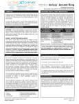
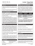
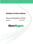
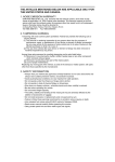
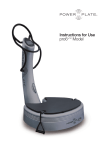
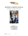
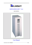
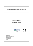
Invisia™ Corner Shelf
Installation Instructions:
INV-CS-BS / INV-CS-CP / 8716.009.002 / 8716.009.295
THANK YOU...
FASTENERS: INSTALLATION & MAINTENANCE
Thank you for purchasing the Invisia™ Corner Shelf. We are
confident that you will find the unique design and durable
construction of this product to be of great assistance in your
daily routine.
The Invisia™ Corner Shelf must be secured to the wall with all
points fastened appropriately to structural wood (wood studs,
reinforced wood framing, etc.). Inspect, or have inspected
(and tighten if necessary) the screws on a monthly basis. See
Page 3 for structural reinforcement suggestions.
To fully enjoy your Invisia™ Corner Shelf, please take a few
moments to read these instructions. You should store these
instructions in a safe place for future reference.
SAFETY CONSIDERATIONS
CAUTION: It is your responsibility to see that your Invisia™
Corner Shelf is properly assembled, installed, and cared for.
Failure to follow instructions in this manual could result in
serious injury. Support rails can be slippery when wet - use
this product with caution.
FULL MOUNTING
STRUCTURE
(RECOMMENDED)
All mount points fasten into structural wood
(wood studs, reinforced wood framing, etc.)
#10 x 2" S/S Screw and Lock Washer (into wood)
500lbs load capacity
INVISIA™ CORNER SHELF INSTALLATION
The Invisia™ Corner Shelf should only be installed in areas
where the mounting surface is structurally sound, in the
corner between 2 walls that are relatively perpendicular to
each other. Strengthening modifications may be required (see
page 3 for details). Should not be installed in fiberglass /
acrylic shower enclosures with insufficient stiffness and
strength. Should not be installed into metal studs. If you are
not equipped to undertake the outlined work we recommend
that you have your Invisia™ Corner Shelf installed by a
qualified contractor. Suggested maximum user weight of
support rail is 500lbs/227kg, however this rating is
conditional upon suitable fasteners and supporting
surface. Tray is not a weight bearing surface.
WARRANTY
TIPS FOR DRILLING INTO TILE
All Invisia™ Collection products are covered by a one year
limited warranty with the exception of hand grips which are
subject to normal wear. Buyer hereby indemnifies, agrees to
hold harmless and defend the manufacturer/ distributor of the
Invisia™ Collection from and against any and all liabilities,
claims, (founded and unfounded), losses, damages, costs
and expenses (including without limitation consequential
damages and reasonable professional fees) resulting from
buyers specification, application, or improper use of goods
described hereon; buyers omission or neglect.
• Use carbide tipped masonry drill on ceramic, or consider a
diamond tip drill for porcelain tile.
The manufacturer/ distributor of the Invisia™ Collection does
not assume any liability for damage resulting from services
performed by others or faulty installation, misuse or
misapplication of goods.
The manufacturer/ distributor of the Invisia™ Collection shall
not be liable for prospective profits or special, indirect, or
consequential damages, or for the cost of any corrective work
done without prior approval. Manufacturer/ distributor of the
Invisia™ Collection total liability hereunder shall in no event
exceed the purchase price of the goods specified hereon.
TOOLS REQUIRED
• Level / Stud Finder
• Hammer
• Center Punch
• Personal Protective Eyewear
• Carbide tip drill suitable for tile
• Protective blanket
Specifications subject to change without notice.
PATENT PENDING.
• If possible, drill a smaller pilot hole first.
• Be careful to prevent the drill from moving when you first
start it rotating - use duct tape or a wood guide on the
surface of the tile to hold the drill from walking sideways.
• A variable speed drill on slow is best to start the hole. Do
not apply too much pressure when drilling. Do not use a
hammer drill.
WATERPROOFING
We recommend that sealant be applied around the wall
contact points for any products mounted in the shower. If not
properly sealed, there is the potential for water to seep into the
wall. This may cause the wood to rot, thus compromising the
structure the support rail is attached to.
SOLID SURFACES: CLEANING AND MAINTENANCE
The tray is made from a durable, non-porous, solid surface
material that resists the growth of bacteria. Clean with general
household cleaners. The surfaces & edges can be sanded
and buffed to repair if necessary.
DC152C / 754921-100
Page 1 of 4
MOUNTING LOCATION
Figure 1.
FA
U
We strongly recommend that you give some thought
as to the optimal location of your Invisia™ Corner
Shelf before installation. The following suggestions are
offered for your consideration, however, it is
recommended to consider advice from the appropriate
healthcare professional for locating any support rail.
CE
E
SID
BA
Ty
pic
froally
m 36flo 60
or. "
CK
To determine the optimal location, we recommend
holding the rail in place and walking through the
motions of a transfer (sitting, standing, reaching, etc.).
Consider the following when determining the optimal
mounting location:
1. Move mounting location to match structure behind
the wall.
2. Avoid electrical / plumbing behind the wall
3. Where possible, drill through tile - not through grout.
RECOMMENDED INSTALLATION LOCATION
Corner of Faucet Wall - Typically 36-60" from floor as
shown in Figure 1. If installing multiple Invisia™ Corner
Shelves, ensure space between is adequate to place
and remove items.
T
Figure 2a.
Figure 2b.
Level
NOT Level
INVISIA™ CORNER SHELF INSTALLATION
Place a blanket down in the area that you will be
installing the Invisia™ Corner Shelf to protect the floor
from parts that may fall during installation. The
proposed mounting location must be cleaned prior to
installation.
Figure 3.
TILE
“LIGHT TAP”
A1. Hold the corner shelf against the walls. Adjust the
corner shelf with a level until it is straight as shown in
Figure 2b.
Cement
Board
A2. Mark the screw hole locations on the wall.
A3. Use the wall plates as a locating guide and notch
the tile with center punch as shown in Figure 3. NOTE:
A light tap is all that is required for punch to make notch.
A4. Use the appropriate drill bit on the notched tile to
drill a pilot hole for the fasteners.
A5. Fasten the Invisia™ Corner Shelf with the
appropriate fastener for wall construction as shown in
Figure 4 and waterproof.
WOOD
STUD
Figure 4.
TAP
CAP
FASTENER
NOTE: Perform a final tighten and inspection of all
fasteners. Test the installation by vigorously pulling on
the support handle of the Invisia™ Corner Shelf.
A6. Install the plastic tap caps to cover the screws.
A7. Place the tray on top of the Invisia™ Corner Shelf,
pushing it against the corner. Install the rubber bumpers
on the bottom of the tray, behind the bent metal bar as
indicated by the
in Figure 4. These rubber bumpers
will hold the tray in place.
WOOD
STUD
Your Invisia™ Corner Shelf is now installed.
Specifications subject to change without notice.
PATENT PENDING.
DC152C / 754921-100
Page 2 of 4
TIPS FOR LOCATING A WOOD STUD
Figure 1.
TILED
BATHROOM
WALL
• For drywall surfaces, use a stud sensor to locate a stud.
• For tile surfaces, try a stud sensor to locate a stud. If no
stud is found, measure 16" from a perpendicular wall. Drill
a small hole in the grout to ensure the stud has been
found. If there is no stud at this location, bend a piece of
wire in a “L” shape and insert it through the hole. Spin the
wire to determine exactly where the stud is located and
mark its location. Patch all holes with silicone to keep
moisture out of the wall.
L
STRUCTURAL REINFORCEMENT SUGGESTIONS
H
H
• If there is access to the backside of the bathroom wall
(i.e. through a closet), measure the stud location and
transfer the measurements into the bath area.
Figure 2a.
Figure 2b.
NOTE: Due to variances in local construction methods
and materials used, details given below are suggestions
only. Consult the appropriate local contractor for specific
advice. For concrete walls, you may be able to install
fasteners (such as a wedge anchor) directly into the
concrete wall without modification.
If there is access to the backside of the bathroom wall (i.e.
through a closet) and structural reinforcement is required,
consider cutting a hole in this backside wall to allow access
to the bathroom wall from behind (without having to
remove / replace ceramic tiles).
1. Choose optimal mounting location of rail including
height (H) and side to side location (L) as shown in Figure
1. Mark the height and location on the wall for future
reference. NOTE: If accessing the bathroom wall from the
backside, transfer the measurements for the support rail
location to the backside wall as shown in Figure 2.
2. Find wall support studs & cut hole in wall board to
expose wall studs as shown in Figure 2. Suggested hole
size is height (A) of 18-24" (48-61cm) and width (B)
corresponding to wall stud spacing. Expose half width of
each stud to facilitate re-installation of wall board patch.
IMPORTANT: Avoid any utilities located in wall!
3. Fabricate a support frame structure from suitable wood
pieces as shown in Figure 2. Support frame width (D)
should fit snugly within wall studs. Support frame height
(E) should be from 24-32" (61-81cm) high or more,
depending on material and stiffness of wall studs. Locate
top cross member (F) to position in in center of mounting
holes when rail is located at the height (H). Hold the
support rail against the support frame to confirm the cross
members are in the correct location. Use a generous
quantity of wood screws and glue to hold the support frame
structure together as shown. See alternative to support
frame as shown in Figure 3.
D
E
F
H
L
WOOD
SCREWS
BACKSIDE
ACCESS TO
BATHROOM
FIGURE 3: ALTERNATIVE TO SUPPORT FRAME - MULTI-LAYER
PLYWOOD INSIDE WALL WITH WALLBOARD PATCH (TOP VIEW)
Bathroom Tile Wall
(CAUTION: Do not puncture
when fastening plywood)
Generous amounts of
wood screws & glue
2" X 2" nom. Stud
(approx 36" high)
Wall Stud
Backside access to bathroom
(insert structure from this side)
Wallboard patch
Figure 4.
A
4. Insert support frame structure through hole in wall and
secure uprights to wall studs using a generous amount of
wood screws.
5. Complete the Invisia™ Corner Shelf installation
instructions on Page 2. Then, patch the wall cutout (if
backside access to bathroom, consider making an access
panel for future servicing) to match the surrounding wall as
shown in Figure 4.
Specifications subject to change without notice.
PATENT PENDING.
Multi-layers of
3/4" plywood
(approx 24" high)
B
DC152C / 754921-100
Page 3 of 4
INVISIA™ CORNER SHELF
CS301
Assembly, Tray, CS
DIMENSIONAL DRAWINGS
CS300 (BS/CP)
Assembly, Corner Shelf, CS
8.81"
(22.4cm)
8.81"
(22.4cm)
3"
(7.6cm)
HARDWARE
HW199
Screw, PPH WS, #10-12 x 2", S/S
Specifications subject to change without notice.
PATENT PENDING.
x4
HW197/198
Tap-Cap
x4
HW505
Bumper, .78", Clear
x2
DC152C / 754921-100
Page 4 of 4