1
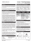
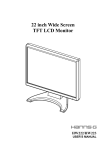
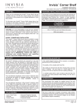
Invisia™ Accent Ring
Installation Instructions:
INV-ACR-BS / INV-ACR-CP / 8712.012.002 / 8712.012.295
THANK YOU...
FASTENERS: INSTALLATION & MAINTENANCE
Thank you for purchasing the Invisia™ Accent Ring. We are
confident that you will find the unique design and durable
construction of this product to be of great assistance in your
daily routine.
The Invisia™ Accent Ring must be secured to the wall with
fasteners appropriate to the structural material. Included are 2
sets of mounting hardware for different wall applications.
Inspect, or have inspected (and tighten if necessary) the
screws on a monthly basis. See Page 3 for structural
reinforcement suggestions. Supplied SnapToggles® can be
used as an alternative to structural reinforcement - ONLY if
the walls have not been compromised and are judged to be
suitably structural (1/2" drywall, or tile walls on 1/2" min
cement board).
To fully enjoy your Invisia™ Accent Ring, please take a few
moments to read these instructions. You should store these
instructions in a safe place for future reference.
SAFETY CONSIDERATIONS
CAUTION: It is your responsibility to see that your Invisia™
Accent Ring is properly assembled, installed, and cared for.
Failure to follow instructions in this manual could result in
serious injury. Support rails can be slippery when wet - use
this product with caution.
INVISIA™ ACCENT RING INSTALLATION
The Invisia™ Accent Ring should only be installed in areas
where the mounting surface is structurally sound. Strengthening
modifications may be required (see page 3 for details). Should
not be installed in fiberglass / acrylic shower enclosures with
insufficient stiffness and strength. Should not be installed into
metal studs. If you are not equipped to undertake the outlined
work we recommend that you have your Invisia™ Accent Ring
installed by a qualified contractor. Suggested maximum user
weight of support rail is 500lbs/227kg, however this rating is
conditional upon suitable fasteners and supporting surface.
FULL MOUNTING
STRUCTURE
(RECOMMENDED)
All mount points fasten
into structural wood
(wood studs,
reinforced wood
framing, etc.)
PARTIAL MOUNTING
STRUCTURE
AVAILABLE
Minimum one mount
point fastens into
structural wood; no
structure available for
other mount points
NO MOUNTING
STRUCTURE
AVAILABLE
None of the mount
points align with the
available structure
#10 x 2" S/S Screw
and Lock Washer (into
wood)
#10 x 2" S/S Screw and
Lock Washer (into wood)
+ SnapToggles® with
#10 x 2" S/S Bolts
(for areas w/o structure)
SnapToggles® with
#10 x 2" S/S Bolts
500lbs load capacity
350lbs load capacity
*200lbs load capacity
* NOTE: FOR INSTALLATIONS USING SNAP TOGGLES®,
WE RECOMMEND A LOWER WEIGHT CAPACITY - FOR
MODERATE WEIGHT SUPPORT APPLICATIONS ONLY.
WARRANTY
TIPS FOR DRILLING INTO TILE
All Invisia™ Collection products are covered by a one year
limited warranty with the exception of hand grips which are
subject to normal wear. Buyer hereby indemnifies, agrees to
hold harmless and defend the manufacturer/ distributor of the
Invisia™ Collection from and against any and all liabilities,
claims, (founded and unfounded), losses, damages, costs
and expenses (including without limitation consequential
damages and reasonable professional fees) resulting from
buyers specification, application, or improper use of goods
described hereon; buyers omission or neglect.
• Use carbide tipped masonry drill on ceramic, or consider a
diamond tip drill for porcelain tile.
The manufacturer/ distributor of the Invisia™ Collection does
not assume any liability for damage resulting from services
performed by others or faulty installation, misuse or
misapplication of goods.
The manufacturer/ distributor of the Invisia™ Collection shall
not be liable for prospective profits or special, indirect, or
consequential damages, or for the cost of any corrective work
done without prior approval. Manufacturer/ distributor of the
Invisia™ Collection total liability hereunder shall in no event
exceed the purchase price of the goods specified hereon.
• If possible, drill a smaller pilot hole first.
• Be careful to prevent the drill from moving when you first
start it rotating - use duct tape or a wood guide on the
surface of the tile to hold the drill from walking sideways.
• A variable speed drill on slow is best to start the hole. Do
not apply too much pressure when drilling. Do not use a
hammer drill.
WATERPROOFING
Although mounting hardware includes rubber gasket washer,
we recommend that sealant be applied around the wall
contact points for any products mounted in the shower. If not
properly sealed, there is the potential for water to seep into the
wall. This may cause the wood to rot, thus compromising the
structure the support rail is attached to.
TOOLS REQUIRED
• Level
• Hammer
• Stud Finder
• Personal Protective Eyewear
• Carbide tip drill suitable for tile
• Protective blanket
Specifications subject to change without notice.
PATENT PENDING.
DC151C / 754917-100
Page 1 of 4
MOUNTING LOCATION
Figure 1.
tive
na ption SIDE
r
e
t
Al ion O
cat
We strongly recommend that you give some thought as to the
optimal location of your Invisia™ Accent Ring before
installation. The following suggestions are offered for your
consideration, however, it is recommended to consider
advice from the appropriate healthcare professional for
locating any support rail.
INVISIA™ ACCENT RING INSTALLATION
T
shCent
o e
Ty wer r wi
pic co th
froally ntro
m 36- ls.
flo 48
or. "
CK
Figure 2a.
Figure 2b.
Wall Stem
Place a blanket down in the area that you will be installing the
Invisia™ Accent Ring to protect the shower or bathtub
surfaces from parts that may fall during installation. The
proposed mounting location must be cleaned prior to
installation.
Refer to the fastener chart on page 1 to determine the size of
hole required for the appropriate wall construction.
CE
BA
To determine the optimal location, we recommend holding
the rail in place and walking through the motions of a transfer
(sitting, standing, reaching, etc.). Consider the following
when determining the optimal mounting location:
1. Ensure shower controls can rotate fully without
interference with rail.
2. If possible, move mounting location to match structure
behind the wall.
3. Avoid electrical / plumbing behind the wall.
4. Where possible, drill through tile - not through grout.
FA
U
Lo
Set
Screw
Rail
Socket
A1. Mark the horizontal and vertical location of the Invisia™
Accent Ring.
A2. Using supplied hex-key, back off set screws in the rail
sockets so the wall stems can move in and out freely as
shown in Figure 2a and 2b.
Figure 3a.
Figure 3b.
A3. On back of wall stems, peel off backing to expose
adhesive side of rubber gasket washer.
A4. With the wall stems inside the rail sockets , push rail
firmly against wall in marked location as shown in Figure 3a.
A5. Remove the rail as straight as possible as to not pull the
wall stems off from the wall as shown in Figure 3b. NOTE:
The peel and stick is not meant to be a permanent adhesive.
A6. Use the wall stem as a locating guide and notch the tile
accurately with supplied center punch as shown in Figure 4.
NOTE: A light tap is all that is required for punch to make notch.
A7. Use the appropriate drill bit on the notched tile to drill a
pilot hole for the fasteners. If SnapToggle® toggle bolts are to
be used, please see the separate installation instructions.
Continue with step A8.
Figure 4.
“LIGHT TAP”
Tile
A8. Fasten the wall stems to the wall with the appropriate
fasteners & waterproofing.
A9. Place the rail back onto the wall stems, and secure rail by
tightening the set screws with supplied hex key as shown in
Figure 5. The rail will pull into the stems as the set screws are
tightened.
The rail will fit best if placed as straight as possible over the
wall stems. If the rail sockets do not easily fit onto the wall
stems at first, this can be adjusted. There is some movement
possible with the oversized hole of the wall stems, and the
location of the wall stems can be adjusted to accommodate
the rail sockets.
NOTE: Perform a final tighten and inspection of all fasteners.
Test the installation by vigorously pulling on the support
handle of the Invisia™ Accent Ring.
Center
Punch
Cement
Board
Wood
Stud
Figure 5.
Lock
Washer
Your Invisia™ Accent Ring is now installed.
Specifications subject to change without notice.
PATENT PENDING.
DC151C / 754917-100
Page 2 of 4
TIPS FOR LOCATING A WOOD STUD
Figure 1a.
Figure 1b.
TILED
BATHROOM
WALL
• For drywall surfaces, use a stud sensor to locate a stud.
• For tile surfaces, try a stud sensor to locate a stud. If no stud
is found, measure 16" from a perpendicular wall. Drill a small
hole in the grout to ensure the stud has been found. If there is
no stud at this location, bend a piece of wire in a “L” shape
and insert it through the hole. Spin the wire to determine
exactly where the stud is located and mark its location. Patch
all holes with silicone to keep moisture out of the wall.
BACKSIDE
ACCESS TO
BATHROOM
A
L
• If there is access to the backside of the bathroom wall (i.e.
through a closet), measure the stud location and transfer the
measurements into the bath area.
B
H
STRUCTURAL REINFORCEMENT SUGGESTIONS
NOTE: Due to variances in local construction methods and
materials used, details given below are suggestions only.
Consult the appropriate local contractor for specific advice.
For concrete walls, you may be able to install fasteners (such
as a wedge anchor) directly into the concrete wall without
modification.
Figure 2a.
D
WOOD
SCREWS
If there is access to the backside of the bathroom wall (i.e.
through a closet) and structural reinforcement is required,
consider cutting a hole in this backside wall to allow access to
the bathroom wall from behind (without having to remove /
replace ceramic tiles).
1. Choose optimal mounting location of rail centered around
the shower controls, including height (H) and side to side
location (L) as shown in Figure 1a. Mark the height and
location on the wall for future reference. NOTE: If accessing
the bathroom wall from the backside, transfer the
measurements for the support rail location to the backside
wall as shown in Figure 1b.
2. Find wall support studs & cut hole in wall board to expose
wall studs as shown in Figure 2a. Suggested hole size is
height (A) of 18-24" (48-61cm) and width (B) corresponding
to wall stud spacing. Expose half width of each stud to
facilitate re-installation of wall board patch. IMPORTANT:
Avoid any utilities located in wall!
3. Fabricate a support frame structure from suitable wood
pieces as shown in Figure 2b. Support frame width (D)
should fit snugly within wall studs. Support frame height (E)
should be from 24-32" (61-81cm) high or more, depending on
material and stiffness of wall studs. Locate top cross member
(F) to position in line with top rail stem when rail is located at
the height (H). Lower cross member (G) should be spaced at
C = 6" (15.36cm) center to center from top cross member.
Hold the support rail against the support frame to confirm the
cross members are in the correct location. Use a generous
quantity of wood screws and glue to hold the support frame
structure together as shown. See alternative to support frame
as shown in Figure 3.
Figure 2b.
F
E
G
C
L
H
FIGURE 3: ALTERNATIVE TO SUPPORT FRAME - MULTI-LAYER
PLYWOOD INSIDE WALL WITH WALLBOARD PATCH (TOP VIEW)
Bathroom Tile Wall
(CAUTION: Do not puncture
when fastening plywood)
Generous amounts of
wood screws & glue
Multi-layers of
3/4" plywood
(approx 24" high)
2" X 2" nom. Stud
(approx 36" high)
Wall Stud
Backside access to bathroom
(insert structure from this side)
Wallboard patch
Figure 4.
4. Insert support frame structure through hole in wall and
secure uprights to wall studs using a generous amount of
wood screws.
5. Complete the Invisia™ Accent Ring installation instructions
on Page 2. Then, patch the wall cutout (if backside access to
bathroom, consider making an access panel for future
servicing) to match the surrounding wall as shown in Figure 4.
Specifications subject to change without notice.
PATENT PENDING.
L
H
DC151C / 754917-100
Page 3 of 4
INVISIA™ ACCENT RING
ACR200 (BS/CP)
Weldment, Handle, ACR
SD302 (x4)
Assembly, Inner Stem with
PSA and Oring, SD
HW222 (x4)
Set Screw, Hex Socket,
10-32 x .25" L, S/S
DIMENSIONAL DRAWINGS
8.4"
(21.34cm)
6.05"
(15.36cm)
9.35"
(23.74cm)
1.5"
(3.8cm)
HARDWARE
HW175
Screw, PPH WS, #10-12 x 3", S/S
HW174
Screw, PPHMS, #10-24 x 3", S/S
HW225
SnapToggle® Toggle Bolt
Specifications subject to change without notice.
PATENT PENDING.
x4
HW177
Washer, Lock,
Split, #10 18-8 S/S
x4
SD107
Bar, Center Punch, SD
x1
HW300
Hex-Key, 3/32 in., Short Arm
x1
x4
x4
DC151C / 754917-100
Page 4 of 4