1
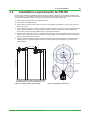
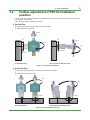
Technical Information Guidelines for Using F9092EY (FN110 Attachment) TI 01W03A51-01EN Contents Introduction....................................................................................................... 2 Revision Information........................................................................................ 2 1. Usage of F9092EY................................................................................... 3 1.1 1.2 1.3 1.4 2. 3. Purpose of using F9092EY.....................................................................................3 Guidelines on whether using F9092EY is necessary..........................................3 Installation requirements for FN110......................................................................4 Further adjustment of FN110 installation position..............................................5 Effect of F9092EY Application................................................................ 6 Parts Information of F9092EY................................................................ 7 Yokogawa Electric Corporation 2-9-32, Nakacho, Musashino-shi, Tokyo, 180-8750 Japan Tel.: 81-422-52-5634 Fax.: 81-422-52-9802 TI 01W03A51-01EN © Copyright Aug. 2015 (KP) 1st Edition Aug. 2015 (KP) 2 <Introduction> <Revision Information> Introduction This guideline explains how to improve communication quality of FN110 Field Wireless Communication Module (hereafter simply referred to as FN110) by attaching F9092EY (FN110 Attachment). This guideline also explains the effect of F9092EY. Regarding This Manual • The contents of this manual are subject to change without prior notice if there are future performance and/ or function improvements. • If any question arises or errors are found, or if any information is missing from this manual, please inform the nearest Yokogawa Sales office. • All rights reserved. No part of this manual may be reproduced in any from without Yokogawa’s written permission. Reference Documents • For details on installing field wireless devices in a system with the YFGW410 field wireless management station and YFGW510 field wireless access point, refer to Guidelines for Layout and Installation of Field Wireless Devices (TI 01W01A51-12EN). • For the usage of FN110, refer to FN110 User’s Manual (IM 01W03B01-01EN) and F9092EY User’s Manual (IM 01W03B01-02EN). Revision Information Title: Guidelines for Using F9092EY (FN110 Attachment) Manual No.: TI 01W03A51-01EN Edition 1st Date August 2015 Page - All Rights Reserved. Copyright © 2015, Yokogawa Electric Corporation Revised Item New Issue TI 01W03A51-01EN Aug. 07, 2015-00 3 <1. Usage of F9092EY> 1. Usage of F9092EY 1.1 Purpose of using F9092EY To make full use of field wireless devices, the optimal installation layout is required. FN110 is more sensitive to the surrounding environment than other Yokogawa field wireless devices because it has a built-in antenna. F9092EY reduces the effects of the surrounding environment to the communication quality, making an installation easier. Therefore, F9092EY offers the same communication quality and allows the same installation point optimization as other Yokogawa field wireless devices. 1.2 Guidelines on whether using F9092EY is necessary (1) Newly installed FN110 • Using F9092EY is recommended. (2) Existing FN110 • If communication quality has been satisfactory, F9092EY is not necessary. • When communication quality is not good (i.e. PER is high), use of F9092EY may improve communication quality. (3) New FN110 for replacement of existing FN110 • Even if the old FN110 does not use F9092EY, using F9092EY is recommended because the replacement may affect the communication quality. • If the old FN110 uses F9092EY, continue to use F9092EY. (4) FN110 for a site survey • Using F9092EY is recommended. If a site survey is carried out using F9092EY, be sure to use F9092EY at the actual installation. All Rights Reserved. Copyright © 2015, Yokogawa Electric Corporation TI 01W03A51-01EN Aug. 07, 2015-00 1.3 4 <1. Usage of F9092EY> Installation requirements for FN110 FN110 must be installed in compliance with the following conditions. Otherwise, communication distances may become shorter. In “pipe jungles”, dense with metal surfaces such as metal pipes and metal racks, the conditions are somewhat different because it is difficult to secure a good line-of-sight in pipe jungles. 1) FN110 must be mounted where no obstacles around. 2) FN110 must be installed vertically. 3)FN110 must be at least 1 meter (3 feet) away from mounting piping or plumbing; in a pipe jungle, 30 centimeters (1 foot) away. 4)If the installation location is too close to walls and the above conditions cannot be met, use a remote antenna cable to prevent obstacles from affecting wireless signals. Unlike other Yokogawa wireless field devices, FN110 does not suffer from signal attenuation by a remote antenna cable. 5)Install FN110 so that it has a good line-of-sight to other antennas in the communication area. Use a remote antenna cable, if necessary. This is not essential in a pipe jungle because it is difficult to secure a good line-ofsight only with a remote antenna cable. 6)When devices are installed at different heights, overlap their communication ranges in consideration of the radiation patterns of respective antennas. FN110 can emit signals up to 45 degrees up or down from the horizontal plane. 1 m or more 1.5 m or higher FN110 45° 1.5 m or higher Horizontal range 45° Vertical range Figure 1.3.1 Requirements for mounting All Rights Reserved. Copyright © 2015, Yokogawa Electric Corporation Figure 1.3.2 Radiation pattern area TI 01W03A51-01EN Aug. 07, 2015-00 1.4 5 <1. Usage of F9092EY> Further adjustment of FN110 installation position If the improvement by applying F9092EY is not satisfactory, further improvement is possible by adjusting the position and angle of the bracket. Follow the steps below for adjusting the bracket. l Vertical Pipe Rotate the bracket to find the position with the lowest PER. Adjust the bracket up or down. FN110 FN110 Bracket Bracket 2-inch pipe 2-inch pipe (a) Direct Mounting (b) Using Remote Antenna Cable Figure 1.4.1 Vertical Pipe Mounting l Horizontal Pipe Adjust the bracket right or left to find the position with the lowest PER. Rotate the bracket upside down. Bracket Bracket 2-inch pipe 2-inch pipe (a) Direct Mounting (b) Using Remote Antenna Cable Figure 1.4.2 Horizontal Pipe Mounting All Rights Reserved. Copyright © 2015, Yokogawa Electric Corporation TI 01W03A51-01EN Aug. 07, 2015-00 . 2.. . 6 <2..Effect.of.F9092EY.Application> Effect.of.F9092EY.Application The radiation pattern of FN110 without F9092EY has weaker areas compared to the ideal. If the communication partner is located in the direction of a weaker area, the communication quality can be unsatisfactory, and can result in additional time for the optimization of the installation position. Attaching F9092EY reduces the weaker areas of radiation pattern and increases the chance of improving communication quality. Figure 2 illustrates the radiation pattern of FN110 before and after F9092EY applied; using F9092EY smoothens the radiation pattern. Radiation pattern 0° Radiation pattern FN110 0° FN110 Ideal radiation pattern Horizontal 90° 270° 90° 270° 180° 45° 45° 180° 45° 45° Vertical Before After Figure.2.Illustrated.radiation.pattern.of.FN110.before.and.after.F9092EY.applied F9092EY is less effective in “pipe jungles”. In the pipe jungles, the effect of the reflections from the surrounding environment is dominant. All Rights Reserved. Copyright © 2015, Yokogawa Electric Corporation TI 01W03A51-01EN Aug. 07, 2015-00 7 <3. Parts Information of F9092EY> 3. Parts Information of F9092EY Attachment *1 Holder 2 Holder 1 Bolt (5 pieces) *1: Attachment side cutout is to support remote FN110 placement, position does not matter for FN110 directly attached to adapters. Figure 3 F9092EY Parts Appearance Table 3 Parts Information of F9092EY No Parts Name Specification 1 Attachment Dimension: Ø50 mm × H24 mm Material: 316 SST (t=1.0 mm) Weight: 34 g 2 Holder 1 Dimension: W35 mm × D28.1 mm × H18 mm Material: 316 SST (t=1.5 mm) Weight: 12 g 3 Holder 2 Dimension: W35 mm × D1.5 mm × H18 mm Material: 316 SST (t=1.5 mm) Weight: 7 g Bolt *2 Type: Hexagon socket head cap screw Nominal diameter: M2.5 Thread length: 5 mm Material: 316 SST or 316L SST Weight: 0.4 g 4 Note Applicable standard: JIS B 1176 and ISO 4762-2004 *2: Bolts meeting the specification and the standards can be used for replacement. All Rights Reserved. Copyright © 2015, Yokogawa Electric Corporation TI 01W03A51-01EN Aug. 07, 2015-00