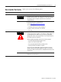
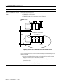
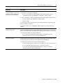
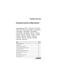
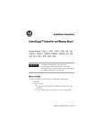
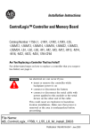
1
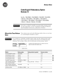
Release Notes
ControlLogix® Redundancy System
Revision 11
Cat. No. 1756-L55, -L55M12, -L55M13, -L55M14, -L55M16,
-L55M22, -L55M23, -L55M24, -CNB/D, -CNBR/D, -ENBT/A,
1757-SRM/A, -SRM/B
IMPORTANT
When to Use These Release
Notes
IMPORTANT
If you have a 1756-L55 controller, you must install a
memory board. For more information, see the
ControlLogix Controller and Memory Board
Installation Instructions, publication 1756-IN101.
These release notes correspond to the following module when used in
a ControlLogix® redundancy system:
Component:
Catalog number:
Revision (or later):
ControlLogix5555™ controller
1756-L55Mxx
11.72
ControlNet™ bridge module
1756-CNB/D or -CNBR/D
5.38
1756 10/100 Mbps EtherNet/IP
Bridge, Twisted Pair Media
1756-ENBT/A
2.3
redundancy module
1757-SRM/A or -SRM/B
3.29
To use a 1756-ENBT module in a redundant controller chassis, make sure the catalog
revision of the module is greater than or equal to E01 (E01, E02, …, F01, etc.).
• To determine the catalog revision of a module, look at the label on the side of the
module or box.
• Using an older ENBT module will prevent the secondary chassis from synchronizing.
ControlLogix
Ethernet/IP 10/100 Mb/s
COMMUNICATIONS BRIDGE
CAT. NO./SERIES
CAT. REV.
1756-ENBT/A
E01
catalog revision
1
Publication 1756-RN582Q-EN-E - July 2004
2
ControlLogix® Redundancy System Revision 11
Compatible Revisions
What Is In These Release
Notes
To use this revision, update your system as follows:
Update this software:
To this revision or later:
RSLinx®
2.41.00 (Build 10.6)
RSLinx hot fix
2.41.00 (Build 10.6)
RSLogix™ 5000
11.11 or a later 11.x revision (not a 12.x
revision)
Microsoft® Internet Explorer
5.01
RSNetWorx™ for ControlNet™
4.11
RSNetWorx™ for DeviceNet™
4.12
These release notes provide the following information about the
components of the redundancy system:
For information about:
See this section:
On this page:
order in which to update your system
How to Update Your System
3
new features
Enhancements
4
how to maintain communication when using a 1756-ENBT module in a
redundant chassis
Use ControlLogix Redundancy Alias Topic 5
Switcher Software
restrictions that no longer apply
Corrected Anomalies
6
restrictions to your redundancy system
Restrictions
9
For more information on the ControlLogix redundancy system, see the
ControlLogix Redundancy System User Manual, publication
1756-UM523.
Publication 1756-RN582Q-EN-E - July 2004
ControlLogix® Redundancy System Revision 11
How to Update Your System
Step:
3
Update your system in the following order:
Details:
Update RSLinx Software
1. Install the RSLinx software.
IMPORTANT
2. Shut down RSLinx software. Also make sure that the RSLinx icon is not
present in the system tray of your computer (icons in the right-hand side of
the Taskbar). If the icon is present, right-click the icon and choose
Shutdown RSLinx.
3. Install the RSLinx hot fix. To get the hot fix:
a. Go to http://support.rockwellautomation.com.
b. Click Knowledgebase.
c. Scroll down and click the Tech Note ID# button.
d. Type the following Tech Note ID #: R13441518
e. Click Find.
Update Firmware
ATTENTION
!
1. Update the SRM module firmware.
It takes several minutes to update a 1757-SRM/A or -SRM/B module. Do
not interrupt the process. Make sure you wait until the SRM module
displays REV 3.29 on its four-character display. If you interrupt the process,
the module may become inoperative.
When you update the module, it performs the following sequence:
• Two downloads (ERAS/PROG on display twice)
• Reset to rev. 2.20 (FLSH UPDT REQD)
• Two more downloads (ERAS/PROG on display twice)
• Second reset before the update is complete
If the OK LED on the SRM module is red flashing and the 4-character
display is blank, then the firmware update has failed. Do not cycle the
power to the module. Leave the power on and update the firmware of the
module again.
2. Update the CNB module firmware.
3. Update the controller firmware.
Publication 1756-RN582Q-EN-E - July 2004
4
ControlLogix® Redundancy System Revision 11
Enhancements
The enhancements are organized by the firmware revision in which
they first appeared.
ControlLogix5555 Rev 11.71
Enhancement:
Description:
Local 1756-ENBT modules
This revision lets you use 1756-ENBT modules in a redundant chassis for communication with HMI
devices.
• Place an ENBT module in the same slot in each redundant chassis. (The modules in each
redundant chassis must match each other slot-by-slot.)
• Place up to 2 ENBT modules in each redundant chassis. The remaining modules must be either
1756-CNB or -CNBR modules, for a total of 5 communication modules per redundant chassis.
redundant
chassis a
L C
5 N
5 B
M
x
E
N
B
T
S
R
M
no other modules
identical modules:
• same slot number
• same catalog number, series, and revision
• same memory size (controller)
redundant
chassis b
L C
5 N
5 B
M
x
E
N
B
T
S
R
M
no other modules
Before you use a 1756-ENBT module in a redundant chassis, complete the following actions:
1. Install RSLinx software, revision 2.41.00 (Build 10.6).
2. Install the ControlLogix Redundancy Alias Topic Switcher software.
The ControlLogix Redundancy Alias Topic Switcher software maintains communication between
your RSView project and the primary controller after a switchover.
• To install the Alias Topic Switcher software, use the ControlLogix Redundancy Alias Topic
Switcher.Exe file. The file is located on the same CD as the firmware for the ENBT module.
• For more information on the Alias Topic Switcher software, see “Use ControlLogix
Redundancy Alias Topic Switcher Software” on page 5.
Store a Project in the
Nonvolatile Memory of a
Secondary Controller
The revision lets you store a project to the nonvolatile memory of a secondary controller while the
primary controller is actively controlling your system.
Publication 1756-RN582Q-EN-E - July 2004
ControlLogix® Redundancy System Revision 11
5
ControlLogix5555 Rev 11.60
Enhancement:
Description:
1756-L55M12 and -L55M22
Controllers
You can use a 1756-L55M12 or -L55M22 controller in a redundant system.
Nonvolatile Memory
You can store or load a project to the nonvolatile memory of a 1756-L55M22, -L55M23, or
-L55M24 controller. For step-by-step procedures, see the ControlLogix Redundancy System User
Manual, publication 1756-UM523.
general enhancements
This revision also contains the enhancements that were previously available to non-redundant
systems via the general releases of Logix revision 10.x and 11.x software and firmware.
For more information on those enhancements, see the following release notes:
• For revision 10.x enhancements, see publication 1756-RN597.
• For revision 11.x enhancements, see publication 1756-RN004.
Use ControlLogix
Redundancy Alias Topic
Switcher Software
IMPORTANT
To use the ControlLogix Redundancy Alias Topic
Switcher software, your computer requires an
activation file for RSLinx software.
• The activation file lets you perform DDE/OPC
communications.
• If you start the Alias Topic Switcher software
without access to an activation file, the following
error occurs:
0x80040112
(The text for the message depends on your
operating system.)
The ControlLogix Redundancy Alias Topic Switcher software works
with RSLinx alias topics to maintain communication between your
HMI and the primary controller after a switchover.
• When you use a 1756-ENBT module in a redundant system, the
module keeps its IP address regardless of which chassis is the
primary chassis. (Only CNB modules swap addresses; ENBT
modules do not swap IP addresses.)
• In your HMI project, each tag must reference an alias topic in
RSLinx software. This lets RSLinx software re-direct
communications to the appropriate chassis.
• The Alias Topic Switcher software automatically determines
which chassis is the primary chassis. The software then points
the alias topic to that chassis.
Publication 1756-RN582Q-EN-E - July 2004
6
ControlLogix® Redundancy System Revision 11
The Alias Topic Switcher software runs as a service. It starts
automatically when you start your computer and shows up in the tool
tray of your desktop.
ControlLogix Redundancy Alias
Topic Switcher
For an example of how to use the Alias Topic Switcher software, see
the following document:
UsingEthernetWithRedundancy.Doc.
The ControlLogix Redundancy CD contains this document along with
the firmware and software for your redundancy system.
Corrected Anomalies
The corrected anomalies are organized by the firmware revision that
corrected them.
ControlLogix5555 Rev 11.72
Anomaly:
Description:
Backplane Errors Caused Loss of
Input Data
Errors that occur for certain backplane-noise conditions caused the data being received by the
controller to stop flowing into the data table of the controller. The controller did not detect when
this happened and the connection status and I/O LED indicators still indicated that everything was
working.
Lgx00047199
Publication 1756-RN582Q-EN-E - July 2004
ControlLogix® Redundancy System Revision 11
7
ControlLogix5555 Rev 11.71
Anomaly:
Description:
Non-Recoverable Fault When a
Disqualified Secondary Controller
Becomes a Primary Controller
The following sequence of events produced a non-recoverable fault (solid red OK and RS232 LEDs)
in the controller:
1. Download a project to a disqualified secondary controller.
2. Turn off the primary controller.
3. Command the disqualified secondary controller to become the primary controller.
When the controller experiences a non-recoverable fault, it clears the project from memory.
Lgx00040144
Simultaneous Power Up Caused the
Secondary Chassis to Fail to
Synchronize
If you turned on the power to both redundant chassis at the same time, the secondary chassis
might not have synchronized. This required you to cycle power to the secondary chassis.
High Number of Messages Might
Have Caused Temporary I/O
Communication Loss After a
Switchover
In some situations, the execution of a large number of Message (MSG) instructions might have
caused a loss of communication with I/O modules for several seconds after a switchover. During
this time, outputs would go to their communication fault state. Communication eventually
re-established.
ControlLogix5555 Rev 11.60
The following anomalies were present in major revision 8 or
preliminary minor revisions of major revision 11:
Anomaly:
Description:
SRM Module in Slot 0
If you placed a 1757-SRM module in slot 0, it might have caused other modules to fault when they
power up.
Absence of I/O Might Have Prevented The following combination of events might have prevented the secondary controller from
Synchronization
synchronizing (both events must have occurred together):
• The primary controller could not communicate with multiple devices in its I/O
configuration. This occurred if multiple nodes were turned off or disconnected from the
ControlNet network.
• The secondary controller became disqualified for any reason.
If this occurred, the Event log of the SRM Configuration software indicated the following:
L55 partner not present
CNB Module Might Have Displayed
PwNS
In very rare instances, a power cycle to the secondary chassis might have caused the CNB module
or modules in the primary chassis to display PwNS on their 4 character display.
Indirect Addressing of an ASCII String You could not download a project that used an indirect address (tag in the subscript of an array) to
a string data type.
SRM Module Placed in a Slot
Configured for Another Module
If you placed the left-hand side of a 1757-SRM module in a slot that was configured for a CNB
module, other modules might have faulted when they powered up.
Switchover Caused a CNB Module to
Fail
In some instances, a switchover might have caused a CNB module to stop communicating (solid
red OK LED). When this occurred, the CNB module displayed a message that started with either of
the following:
• ASSERT…
• FAULT…
Publication 1756-RN582Q-EN-E - July 2004
8
ControlLogix® Redundancy System Revision 11
Anomaly:
Description:
Major Fault During Prescan
If a major fault occurred during prescan (i.e., change from program mode to run mode), a
switchover might not have occurred and the secondary controller might have experienced a
non-recoverable fault (solid red OK LED). If this occurred, you had to manually clear the fault and
then cycle power to the secondary chassis.
CIP Data Table Write Messages
Failed
In a synchronized system, Message (MSG) instructions that were configured as CIP Data Table
Write did not work. The instruction did not write the data and its ER bit was set.
Online Edits Might Have Corrupted
the Project in the Secondary
Controller
If you performed online edits in a synchronized system, you might have corrupted the project in
the secondary controller. To avoid this situation, you had to perform online edits while the
secondary chassis was disqualified.
Creating a Task or Program Online
In a synchronized system, if you created a task or program while online with the controller the
secondary chassis might have disqualified.
Power Disruptions Cleared Memory
If power to the controller turned on and then turned off again in less than a second, the controller
might have cleared the project from its memory. This might have occurred during brownouts or
other situations where power to the controller fluctuated for a short duration.
Secondary Chassis Failed to
Synchronize
In rare instances, the secondary chassis might have failed to synchronize after a switchover and
required manual intervention:
If a:
Then you had to:
secondary controller was faulted (task
watchdog)
Clear the fault.
CNB module in either chassis displayed Use the SRM Module Configuration dialog box in
a no partner (PwNS, DSNP) condition
RSLinx software to synchronize the secondary chassis.
on its 4 character display
ControlNet Trunk Line Break Caused
the Secondary Chassis to Disqualify
If a ControlNet trunk line broke and was re-connected, the secondary chassis might have
disqualified and then automatically synchronized. During this time the primary chassis maintained
control of the system.
Task Watchdog Fault
In the following situations, either a primary or secondary controller might have experienced a
major fault (flashing red OK LED) due to the watchdog timer of a task:
• In a synchronized system, a failure of a primary CNB module caused the system to switch
to the secondary chassis. But the controller that was previously the primary controller was
left with a task watchdog fault.
• In a system with a disqualified secondary chassis, a failure of a primary CNB module
caused the primary controller to experience a task watchdog fault. No switchover
occurred.
You had to manually clear the fault from either the controller.
Controller Failed to Reconnect with a
Remote Chassis
Under the following combination of circumstances, a controller was sometimes unable to
re-establish connections with a remote chassis (both must have occurred):
• The remote chassis contained a 1756-CNB/B or -CNBR/B module.
• You disconnected the remote chassis during a switchover.
Communication with a Device Over
RIO Sometimes Failed
Publication 1756-RN582Q-EN-E - July 2004
If your system communicated with I/O over a universal remote I/O network, the following could
have occurred:
• If power was cycled to the remote device, the controller might not reestablish
communication with the device. In the Properties dialog box of the remote I/O adapter for
the device, the Status line displayed “Shutting Down.”
ControlLogix® Redundancy System Revision 11
Restrictions
9
This revision contains the following restrictions:
IMPORTANT
In a redundant system, use an EtherNet/IP network only for
HMI/workstation communication. For HMI communication, establish
the communication via OPC topics.
Do not use an EtherNet/IP network for:
• communication with I/O modules
• communication between devices via produced/consumed tags
Restriction:
Description:
Online Editing During a Switchover
In some instances, RSLogix 5000 software may not let you perform additional online edits of a
function block diagram. This may occur if you edit the function block diagram while online and the
system is switching over and synchronizing.
If this occurs:
1. Close and then open RSLogix 5000 software.
2. Upload the RSLogix 5000 project from the primary controller.
Deleting a Task Online
If you delete a task while online with the controller, the secondary chassis may disqualify and
then synchronize.
Motion Control
You cannot use the ControlLogix redundancy system in applications that require motion control.
(I.e., You cannot use a 1756-M02AE, -M08SE, or -M16SE module.)
Sequential Function Charts
You cannot use the sequential function chart (SFC) programming language to program your
redundancy system. If you attempt to download a project with an SFC, the download fails and you
get the following error message: “Attribute list error.”
ASCII Instructions May Prevent the
Secondary Controller From
Synchronizing
After you download a project that contains ASCII instructions (e.g., ABL, ACB) to a pair of
redundant controllers, the secondary controller may disqualify and fail to synchronize. If this
occurs, turn off both controllers (primary and secondary) and then turn the controllers back on.
Controller May Momentarily Drop Its
Connection to a Digital I/O Module
In rare instances, if a tap to a 1756-CNB module is disconnected or breaks, the primary controller
may monetarily drop its connection to a digital I/O module. The connection automatically
re-establishes.
To minimize this, use redundant ControlNet media. Redundant ControlNet media prevents a loss
of communication if a trunkline or tap is severed or disconnected.
Publication 1756-RN582Q-EN-E - July 2004
10
ControlLogix® Redundancy System Revision 11
Restriction:
Description:
Communication Loss When Bridging
Through a 1756-CNB/B or -CNBR/B
Module
The following combination of modules in a remote chassis could cause a temporary
communication loss with the chassis:
• 1756-CNB/B or -CNBR/B module
• 1756-DHRIO module that is connected to a remote I/O network.
redundant chassis
pair
L C
5 N
5 B
M
x
S
R
M
1756-CNB/B or -CNBR/B module
remote
chassis
C
N
B
/
B
other modules
D
H
R
I
O
remote I/O
On the first switchover after you download a project to the controller, you may
temporarily lose communications with these devices.
The loss of communication occurs on the first switchover after you download the project to the
redundant controller.
• You lose communication with the remote chassis and any devices to which you were
bridging via the chassis, such as the remote I/O modules.
• During the communication loss, the I/O modules go to their configured state for a
communication fault.
• The communication loss is temporary. Communications restore themselves.
To prevent this situation, use 1756-CNB/D or -CNBR/D modules.
Publication 1756-RN582Q-EN-E - July 2004
ControlLogix® Redundancy System Revision 11
Restriction:
Description:
If the Lowest Node Is a 1756-CNB/B
or -CNBR/B Module, Removing a Tap
or Breaking a Cable Could Stop All
Communications over the Network
If the lowest node on a ControlNet network is a 1756-CNB/B or -CNBR/B module, all
communications over the network could stop if:
11
• A tap to the 1756-CNB/B or -CNBR/B module is disconnected or breaks and then is
replaced while power is still applied to the 1756-CNB/B or -CNBR/B module
If a tap to a 1756-CNB/B or -CNBR/B module becomes disconnected or broken, take these actions:
1. Turn off the power to the 1756-CNB/B or -CNBR/B module.
2. Replace the tap.
If a communication failure occurs because of a disconnected or broken tap, cycle power to each
primary controller on the network.
To prevent this situation, use a 1756-CNB/D or -CNBR/D module as your lowest node on the
network.
1756-L55M16 Controllers Have a
3.5M Byte Limit of Tags
You cannot download a project that has more than 3.5M bytes of data to a 1756-L55M16
controller. (For redundancy operations, the controller requires enough memory for 2 copies of all
data.) During the download, RSLogix 5000 software indicates that the controller is out of memory.
To stay within the 3.5M byte limit, take this precaution:
• As you create tags, periodically download the project. If the project successfully
downloads, then you know you are within the 3.5M byte limit.
1756-L55M16 Controllers: Guidelines
for the Size of Routines
You cannot download a project that has very large routines. During the download, RSLogix 5000
software indicates that the controller is out of memory. (While online, you may be able to create a
very large routine, but once offline you will be unable to download the project.)
To avoid creating routines that are too large, take these precautions:
• Limit the number of rungs in a routine to less than 2500. (Use a series of smaller routines.)
• If you are entering a large number of rungs in a routine, do this offline.
• As you enter rungs, periodically download the project. If the project successfully
downloads, then your routines are within limits.
Publication 1756-RN582Q-EN-E - July 2004
Rockwell Automation Support
Rockwell Automation provides technical information on the web to assist you in using our products. At
http://support.rockwellautomation.com, you can find technical manuals, a knowledge base of FAQs, technical and
application notes, sample code and links to software service packs, and a MySupport feature that you can customize
to make the best use of these tools.
For an additional level of technical phone support for installation, configuration and troubleshooting, we offer
TechConnect Support programs. For more information, contact your local distributor or Rockwell Automation
representative, or visit http://support.rockwellautomation.com.
Installation Assistance
If you experience a problem with a hardware module within the first 24 hours of installation, please review the
information that's contained in this manual. You can also contact a special Customer Support number for initial help
in getting your module up and running:
United States
1.440.646.3223
Monday – Friday, 8am – 5pm EST
Outside United States
Please contact your local Rockwell Automation representative for any technical support issues.
New Product Satisfaction Return
Rockwell tests all of our products to ensure that they are fully operational when shipped from the manufacturing
facility. However, if your product is not functioning and needs to be returned:
United States
Contact your distributor. You must provide a Customer Support case number (see phone number
above to obtain one) to your distributor in order to complete the return process.
Outside United States
Please contact your local Rockwell Automation representative for return procedure.
Back Cover
Publication 1756-RN582Q-EN-E - July 2004 12
Supersedes Publication 1756-RN582P-EN-E - August 2003
PN 957928-07
Copyright © 2004 Rockwell Automation, Inc. All rights reserved. Printed in the U.S.A.