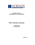
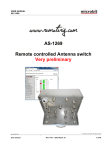
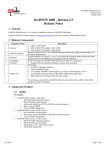
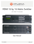
1
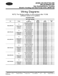
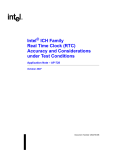
This Datasheet is for the
IC693ALG442
Analog Current/Voltage Combination Module
4 Input/2 Output Channels
http://www.cimtecautomation.com/parts/p-14577-ic693alg442.aspx
Provides the wiring diagrams and installation guidelines for this GE Series 90-30
module.
For further information, please contact Qualitrol Technical Support at
1-800-784-9385
[email protected]
Chapter 12 IC693ALG442 Analog Combination I/O
section level 1 1
Module
figure bi level 1
12
table_big level 1
Analog Current/Voltage Combination Module
4 Input/2 Output Channels - IC693ALG442
The Analog Current/Voltage Combination Input/Output module provides up to 4 differential
input current or voltage channels and 2 single-ended output channels with either current loop
outputs or voltage outputs. Each channel can be individually configured for the current or
voltage range, as applicable, required for your application. All module configuration is done
through software, except for a jumper required for selecting the current input mode. All ranges
can be configured using either the Logicmaster 90-30/20/Micro programming software
configurator function or the Series 90-30 Hand-Held Programmer.
Note that in this module’s description, the module will be simply referred to as the Analog Combo
Module.
Each analog input is capable of providing five input ranges (two voltage and three current),
which are:
0 to +10 volts (unipolar) - default range for both input and output channels.
–10 to +10 volts (bipolar)
0 to 20 mA
4 to 20 mA
4 to 20 mA Enhanced
The default input range is voltage mode 0 to +10 volts (unipolar) with user data scaled so that
0V corresponds to a count of 0 and 10V corresponds to a count of 32767.
Each analog output is capable of providing four output ranges (two voltage and two current):
0 to +10 volts (unipolar) - default range for both input and output channels.
–10 to +10 volts (bipolar)
0 to 20 milliamps
4 to 20 milliamps
Each output channel is capable of converting 15 to 16 bits (depending on the range selected) of
binary (digital) data to an analog output for use as required by your application. User data in
GFK-0898F
12-1
12
the%AI and %AQ registers is in a 16-bit 2’s complement format. In current modes, an open-wire
fault is reported to the CPU for each channel. The module can go to a known last state when
system power is interrupted. As long as user power is applied to the module, each output will
maintain its last value, or reset to the low end of the scale (range), as determined by how you have
configured the module.
Each output channel can be configured to operate in ramp mode using ladder logic. In ramp
mode, changes in %AQ data cause the corresponding output channel to ramp to the new %AQ
value. The ramp output consists of steps taken each millisecond until the final value is reached.
High and low alarm limits can be set for all input channels and an open-wire fault (current
output modes) is reported to the CPU for each output channel. All six analog channels may be
updated on every scan, depending on the scan time.
Table 12-1. Specifications for IC693ALG442
Analog Output Specifications
Number of Output Channels
Update Rate
2, Single-Ended
4 milliseconds (approximate - both channels)
Analog Current Output
Output Current Ranges
Resolution
0 to 20 mA
4 to 20 mA
Absolute Accuracy1
All Current Modes
Maximum Compliance Voltage
User Load
Output Load Capacitance
Output Load Inductance
Analog Voltage Output
Output Ranges
Resolution
–10 to +10V
0 to +10V
Absolute Accuracy2
Both Voltage Modes
Output Loading
Output Load Capacitance
Analog Input Specifications
Number of Input Channels
Update Rate
Analog Current Input
12-2
0 to 20 mA
4 to 20 mA
0.625 µA (1 LSB = 0.625 µA)
0.5 µA (1 LSB = 0.5 µA)
± 0.1% of full scale @25°C (77°F), typical
± 0.25% of full scale @25°C (77°F), (maximum)
± 0.5% of full scale over operating temperature range (maximum)
VUSER –3V (minimum) to VUSER (maximum)
0 to 850 Ω (minimum) at VUSER =20V,
maximum 1350Ω at VUSER =30V
2000 pF (maximum)
1 H (maximum)
–10 to +10V (bipolar)
0 to +10V (unipolar)
0.3125 mV (1 LSB = 0.3125 mV)
0.3125 mV (1 LSB = 0.3125 mV)
± 0.25% of full scale @25°C (77°F), typical
± 0.5% of full scale @25°C (77°F), (maximum)
± 1.0% of full scale over operating temperature range (maximum)
5 mA (2K ohms minimum resistance)
1 µF (maximum capacitance)
4, differential
8 milliseconds (approximate for all 4 channels)
Series 90–30 PLC I/O Module Specifications – July 2000
GFK–0898F
IC693ALG442 Analog Combination I/O Module
Input Ranges
12
0 to 20 mA
4 to 20 mA
4 to 20 mA Enhanced
(Table continued on next page)
(Continued from previous page)
Resolution
0 to 20 mA
4 to 20 mA
4 to 20 mA Enhanced
Absolute Accuracy3
All Current Modes
Linearity
Common Mode Voltage
Common Mode Rejection
Cross Channel Rejection
Input Impedance
Input Filter Response
Analog Voltage Input
Input Ranges
Resolution
0 to +10V
–10 to +10V
Absolute Accuracy3
Both Voltage Ranges
Linearity
Common Mode Voltage
Common Mode Rejection
Cross Channel Rejection
Input Impedance
Input Filter Response
Power Requirements
External Supply Voltage Range
Power Supply Rejection Ratio
(PSRR)4
Current
Voltage
Voltage Ripple
Current Consumption
From Internal +5V Supply
From External User Supply
5 µA (1 LSB = 5 µA)
5 µA (1 LSB = 5 µA)
5 µA (1 LSB = 5 µA)
± 0.25% of full scale @25°C (77°F)
± 0.5% of full scale over specified operating temperature range
<1 LSB
200V (maximum)
>70 db at DC; >70 db at 60 Hz
>80 db from DC to 1 kHz
250 Ω
29 Hz
0 to +10V (unipolar)
–10 to +10V (bipolar)
2.5 mV (1 LSB = 2.5 mV)
5 mV (1 LSB = 5 mV)
± 0.25% of full scale @25°C (77°F)
± 0.5% of full scale over specified operating temperature range
<1 LSB
200V (maximum)
>70 db at DC; >70 db at 60 Hz
>80 db from DC to 1 kHz
800K Ω (typical)
29 Hz
20 to 30 VDC (24 VDC typical)
5 µA/V (typical), 10µA/V (maximum)
25 mV/V (typical), 50mV/V (maximum)
10%
95 mA
129 mA
1In the presence of severe RF interference (IEC 801-3, 10V/m), accuracy may be degraded to ±1%
FS.
2In the presence of severe RF interference (IEC 801-3, 10V/m), accuracy may be degraded to ±4%
FS.
3In the presence of severe RF interference (IEC 801-3, 10V/m), accuracy may be degraded to ±2%
FS.
4PSSR
is measured by varying VUSER from 24V to 30V.
Refer to Appendix B for product standards and general specifications.
GFK–0898F
Chapter12 – IC693ALG442 Analog Combination I/O Module
12-3
12
IC693ALG442 Input Modes and Current/Voltage Ranges
Current Operation
In the 4 to 20 mA range, user data is scaled so that 4 mA corresponds to a count of 0 and 20 mA
corresponds to a count of 32000. The other ranges are selected by changing the configuration
parameters using the Logicmaster 90-30/20/Micro configurator software or the Hand-Held
Programmer. In the 0 to 20 mA range user data is scaled so that 0 mA corresponds to a count of 0
and 20 mA corresponds to a count of 32000. Full 12-bit resolution is available over the 0 to 20 mA
range.
A 4 to 20 mA Enhanced range can also be selected. When this range is selected, 0 mA corresponds
to a count of –8000, 4 mA corresponds to a count of 0 (zero) and 20 mA corresponds to a count of
+32000. The Enhanced range uses the same hardware as the 0 to 20 mA range but automatically
provides 4 to 20 mA range scaling with the exception that negative digital values are provided to
the user for input current levels between 4 mA and 0 mA. This gives you the capability of
selecting a low alarm limit that detects when the input current falls from 4 mA to 0 mA, which
provides for open-wire fault detection in 4 to 20 mA applications. High and Low alarm limits are
available on all ranges. Ranges can be configured on a per channel basis.
User data in the %AI registers is in 16-bit 2’s complement format (0 to 20 mA range only).
Resolution of the converted signal is 12 bits binary (1 part in 4096) on the 0 to 20 mA range.
The placement of the 12 bits from the A/D converter in the %AI data word is shown below.
LSB
MSB
X
D11
D10
D9
D8
D7
D6
D5
D4
D3
D2
D1
D0
X
X
X
X=not applicable to this discussion.
The relationship between the current input and the data from the A/D converter is show below.
a44647
a44654
4000
4000
A/D
BITS
(decimal)
A/D
(decimal)
0
0
0
4
20
0
20
CURRENT (mA)
CURRENT (mA)
4 to 20mA RANGE
0 to 20 mA RANGE
Figure 12-1. A/D Bits vs. Current Input
If the current source is reversed into the input, or is less than the low end of the current range,
then the module will output a data word corresponding to the low end of the current range
(0000H in %AI). If an input that is out of range is entered (that is, it is greater than 20 mA), the
A/D converter will output up to full scale (corresponding to 7FFFH in %AI).
Voltage Operation
In the 0 to +10 V default range, user data is scaled so that 0 volts corresponds to a count of 0 and
+10 volts corresponds to a count of 32000. The –10 to +10 volt range is selected by changing the
12-4
Series 90–30 PLC I/O Module Specifications – July 2000
GFK–0898F
IC693ALG442 Analog Combination I/O Module
12
configuration parameters using the Logicmaster 90-30/20/Micro configurator software or the
Hand-Held Programmer. In the –10 to +10 volt range user data is scaled so that –10 volts
corresponds to a count of –32000 and +10 volts corresponds to a count of +32000. Full 12-bit
resolution is available over either range.
Since converters used in the analog input channels are 12-bit converters, not all of the 16 bits in
the data tables contain data required for the conversion. A version of the 12 bits is placed
within the 16-bit data word corresponding to the analog point (in the %AI table). The Series
90-30 PLC system handles the integration differently for the various analog modules.
The CPU does not manipulate the data from the input channels before placing it within the
word in the %AI data table. The bits in the %AI data table which were not used in the
conversion by the input channel are forced to 0 (zero) by the analog input channel. Placement
of the 12 data bits from the A/D converter for an analog current input data word for the
16-Channel Analog Voltage Input module in unipolar range is shown below.
LSB
MSB
X
D11 D10
D9
D8
D7
D6
D5
D4
D3
D2
D1
D0
X
X
X
X=not converted bits
Analog values are scaled over the range of the converter. Factory calibration adjusts the analog
value per bit (resolution) to a multiple of full scale (that is, 2.5 mV/bit for unipolar; 5 mV/bit
for bipolar). This calibration leaves a normal 12-bit converter with 4000 counts (normally 212
= 4096 counts). The data is then scaled with the 4000 counts over the analog range. For
example, the data to the A/D converter for the Analog Voltage Input is scaled as shown below.
a45717
4000
A/D
BITS
(decimal)
0
0
VOLTAGE; 0 to 10V RANGE
10
Figure 12-2. A/D Bits vs. Voltage Input
GFK–0898F
Chapter12 – IC693ALG442 Analog Combination I/O Module
12-5
12
IC693ALG442 Output Modes and Current/Voltage Ranges
Current Operation
In the 4 to 20 mA range user data is scaled so that 4 mA corresponds to a count of 0 and 20 mA
corresponds to a count of 32767. In the 0 to 20 mA range, user data is scaled so that 0 mA
corresponds to a count of 0 and 20 mA corresponds to 32000. Note that in the 0 to 20 mA
mode, you can enter a value up to 32767 which provides a maximum output of approximately
20.5 mA. Scaling of the current output for both the 4 to 20 mA range and the 0 to 20 mA range
is shown below. In current mode the module also provides an open loop fault detect which is
reported to the PLC in the %I table.
a44684
a44683
32000
32000
%AQ
(decimal)
%AQ
(decimal)
0
0
0
4
CURRENT (mA)
0
20
CURRENT (mA)
4 to 20 mA Range
20
0 to 20 mA Range
Figure 12-3. Scaling for Current Output
Voltage Operation
For Voltage Operation in the default unipolar mode (0 to +10 volts), user data is scaled so that 0
volts corresponds to a count of 0 and +10 volts corresponds to a count of 32000. In this mode,
you can enter up to 32767 for an overrange of approximately 10.24 volts output. In the –10 to
+10 volt range user data is scaled so that –10 volts corresponds to a count of –32000 and +10
volts corresponds to a count of +32000. In this range, you can enter –32768 to +32767 for an
overrange of approximately –10.24 volts to +10.24 volts.
Scaling of the voltage output for both the 0 to +10 volt range and the –10 to +10 volt range is
as shown below.
a45718
a44658
32000
32000
%AQ
(decimal)
%AQ
0
(decimal)
0
32000
10
0
VOLTAGE (V)
10
Bipolar Mode
0
10
VOLTAGE (V)
Unipolar Mode
Figure 12-4. Scaling for Voltage Output
12-6
Series 90–30 PLC I/O Module Specifications – July 2000
GFK–0898F
IC693ALG442 Analog Combination I/O Module
12
CPU Interface to the IC693ALG442 Analog Combo Module
The Series 90-30 PLC uses the data within the %AI and %AQ data table to record analog
values for use by the programmable controller. For detailed information on the CPU interface
to analog modules, refer to the “Hardware Description of Analog Module” section at the
beginning of this chapter.
Status Reporting
The Analog Combo module module provides status information to the PLC. This status
information is updated once each PLC sweep and consists of the following items:
health of the module (all ranges)
overload or open wire detect (current output mode only)
alarm low and high status (input channels)
status of the user-supplied power to the module (all ranges)
Power Requirements and LEDs
This module requires a maximum of 95 mA from the 5V bus on the PLC backplane for the logic
side. The module’s analog power must be supplied by a single, user supplied+24 VDC power
source. This includes current loop output power and voltage output load power. This user supply
requires a maximum current of 129 mA.
There are two green LED indicators on the module which provide module and user supply
status. The top LED, OK, provides module status information, and the bottom LED, USOK,
indicates whether the user supply is present and is above a minimum designated level. Note
that both LEDs are powered from the +5V backplane power bus.
The LEDs have six possible status combinations, which are described below.
LED Status Indications for IC693MDL442
Combination
LED
Status
Description
1
OK
USOK
ON
ON
2
OK
USOK
FLASH
OFF
Module OK but not configured
No user power
3
OK
USOK
FLASH
ON
Module OK but not configured
User power is present
4
OK
USOK
ON
OFF
Module OK and configured
No user power
5
OK
USOK
OFF
OFF
Module is defective or no +5V backplane power present
User power may or may not be present
6
OK
USOK
OFF
ON
Module not OK
User power is present
Module OK and configured
User power is present
Location in System
The Analog Combo module is compatible with all Series 90–30 CPU models and may be installed
in any I/O slot of any Series 90–30 baseplate.
GFK–0898F
Chapter12 – IC693ALG442 Analog Combination I/O Module
12-7
12
References Used and Maximum Modules per System Considerations
The number of IC693ALG442 Analog Combo modules that can be installed in a system depends
on the amount of %AQ, %AI, and %I references available. Each module uses 2 %AQ references
and 4 %AI references (depending on status configuration) and 8, 16 or 24 %I references (depending
on alarm status configuration). The number of these references is dependent on the type of CPU in
your system.
Please refer the the “Maximum Number of Analog Modules per System” table in Chapter 8 to
determine how many Analog Combo modules can be installed for the various CPU models.
12-8
Series 90–30 PLC I/O Module Specifications – July 2000
GFK–0898F
IC693ALG442 Analog Combination I/O Module
12
IC693ALG442 Analog Module Field Wiring Connections
Connections to this module from user devices are made to screw terminals on a removable
20-terminal connector block mounted on the front of the module. The actual terminals used are
described in the following table and are shown in the following wiring diagrams.
Terminal Assignments
Pin assignments for the 20 terminal I/O connector on the Analog Combo module are as shown
in the following table.
Table 12-2. Terminal Pin Assignments for IC693ALG442
GFK–0898F
Pin
Number
Signal
Name
1
24VIN
User Supplied +24 Volt Input
2
JMP1
Jumper terminal for connecting 250Ω sense resistor for CH1
3
JMP2
Jumper terminal for connecting 250Ω sense resistor for CH2
4
+CH1
Positive connection for differential analog input channel 1
5
+CH2
Positive connection for differential analog input channel 2
6
–CH1
Negative connection for differential analog input channel 1
7
–CH2
Negative connection for differential analog input channel 2
8
JMP3
Jumper terminal for connecting 250Ω sense resistor for CH3
9
JMP4
Jumper terminal for connecting 250Ω sense resistor for CH4
10
+CH3
Positive connection for differential analog input channel 3
11
+CH4
Positive connection for differential analog input channel 4
12
–CH3
Negative connection for differential analog input channel 3
13
–CH4
Negative connection for differential analog input channel 4
14
Vout CH1
Voltage output for channel 1
15
Iout CH1
Current output for channel 1
16
Vout CH2
Voltage output for channel 2
17
Iout CH2
Current output for channel 2
18
V COM
Common return for voltage outputs
19
I RET
Common return for User supplied +24 V and current outputs
20
GND
Frame ground connections for cable shields
Signal Definition
Chapter12 – IC693ALG442 Analog Combination I/O Module
12-9
12
IC693ALG442 Analog Combo Module Field Wiring Diagram
The following figure provide information for connecting field wiring to the user terminal board
on the Analog Combo module.
a47047
TERMINALS
FIELD WIRING
FIELD WIRING
24VIN
1
2
*
IN1
5
6
IN2
8
Vuser
JMP4
–
(–)
7
(–)
+
(+)
4
JMP2
(+)
*
JMP1
3
*
(+)
10
(+)
12
IN3
(–)
11
IN4
(–)
*
JMP3
9
13
14
ICH1
15
VCH1
16
ICH2
VCH2
17
18
COM (I RET)
V COM
19
20
*
**
FGND **
ADD JMP1 - JMP4 for 250Ω SENSE RESISTOR (CURRENT INPUT MODE ONLY)
OPTIONAL SHIELD CONNECTION
Figure 12-5. Field Wiring for Analog Combo Module - IC693ALG442
Notes
12-10
1.
Each Input channel can be configured independent of other Input channels to
operate as a voltage input or a current input – not both simultaneously.
2.
Each Output channel can be configured independent of other Output channels to
operate as a voltage output or a current output – not both simultaneously.
3.
Please see Chapter 2 for wiring and shield ground connection information.
Series 90–30 PLC I/O Module Specifications – July 2000
GFK–0898F
IC693ALG442 Analog Combination I/O Module
12
IC693ALG442 Analog Combo Module Block Diagram
The following figure is a block diagram of the Analog Combo module.
a47046
LEDs
O
CHX
X4
O
CURRENT/VOLTAGE
INPUT SELECT
A/D
JMPX O
VIN O
COM O
MICRO
PROCESSOR
REFERENCE
+ 15V
15V
5V
5V
POWER
CONVERTER
EPROM
FGND O
OPTO
ISOLATION
RAM
VOLTAGE
SUPERVISOR
EEPROM
DATA
TRANSMIT/RECEIVE
MULTIPLEXOR
Iout O
D/A
CURRENT
DRIVER
BACKPLANE
INTERFACE VLSI
CONFIG
SR/LATCH
ÎÎÎÎÎÎÎ
ÎÎÎÎÎÎÎ
SERIES 90–30 PLC
BACKPLANE
VOUT O
VCOM O
VOLTAGE
OUTPUT
RANGE
SELECT
FAULT
SR/LATCH
Figure 12-6. Analog Combo Module Block Diagram - IC693ALG442
GFK–0898F
Chapter12 – IC693ALG442 Analog Combination I/O Module
12-11
12
Configuring the IC693ALG442 Analog Combo Module
The Analog Combo module can be configured using the Logicmaster, VersaPro, or Control
programming software configurator function, or with the GE Fanuc Hand-Held Programmer.
The parameters that can be configured are described in the following table. Configuration
procedures using Logicmaster 90-30/20/Micro Programming Software and the Hand-Held
Programmer are described in the following pages.
Table 12-3. Configuration Parameters for IC693ALG442
Parameter
Description
Values
Defaults
Units
STOP
MODE
Output state when module toggled
from RUN to STOP mode
HOLD or DEFLOW
HOLD
N/A
%AI ADR
Starting address for the %AI
reference type
standard range
%AI0001, or next highest
available reference
N/A
%AQ ADR
Starting address for the %AQ
reference type.
standard range
%AQ0001, or next highest
available reference
N/A
%I ADR
Starting address for the %I
reference type
standard range
%I0001, or next highest
available reference
N/A
%I SIZE
Number of %I status locations
8, 16, 24
8
bits
RANGE
OUTPUT
0,+10 V,
–10,+10 V,
4,20 mA, 0, 20mA
0,+10 V
Type of output range
volts (Voltage)
mA (Current)
RANGE
INPUT
0,+10 V, –10,+10 V,
4,20 mA, 0, 20mA,
4-20 mA Enhanced
0,+10 V
Type of input range
volts (Voltage)
mA (Current)
ALARM LO
Low limit alarm value
–32768 to 32759
0
User counts
ALARM
HIGH
High limit alarm value
–32767 to 32760
+32000
User counts
For detailed information on configuration of the Analog Combo module, see
12-12
Configuration Using Logicmaster 90-30/20/Micro Programming Software
beginning on page 3-93.
Configuration Using the Hand-Held Programmer beginning on page 3-104.
Series 90–30 PLC I/O Module Specifications – July 2000
GFK–0898F
12
IC693ALG442 Analog Combination I/O Module
Configuring IC693ALG442 Using Logicmaster Software
This section describes how to configure the IC693ALG442 Analog Combination module using the
configurator function in Logicmaster 90-30/20/Micro Programming Software. Configuration can
also be done using VersaPro or Control Programming Software. For details refer to the VersaPro
or Control online help.
To configure an Analog Combo module on the I/O Configuration Rack screen, follow these
steps:
GFK–0898F
1.
Move the cursor to the desired rack and slot location. The slot may be either unconfigured
or previously configured.
2.
Press the lm30 io key (F1). Your screen will change to one similar to the one shown
below.
3.
From this screen, press the a mix key (F6). Your screen will change to one similar to the
one shown below.
Chapter12 – IC693ALG442 Analog Combination I/O Module
12-13
12
4.
Currently, there is only one selection. (If more than one selection appears, use your Cursor
Movement (or Arrow) keys to move to Catalog # IC693ALG442.) Press Enter to accept
this selection and to move to the screen shown below.
5.
All the remaining configuration does not have to be done on this screen. You can move
your cursor from field to field by pressing the Cursor Movement (or Arrow) keys.
When you are in the field you want to modify, you can either type in your choice or press
the Tab key to scroll through the available selections (or Shift-Tab to reverse the
direction of the scrolling).
Note
The entry in the Stop Mode field (HOLD or DEFLOW (DEFault LOW))
determines how the outputs will behave when the module is toggled from RUN to
STOP mode. When this value is set to HOLD (default), the outputs will retain
their last state. When you change this value to DEFLOW, the output will go to
zero.
Other Configuration Considerations
The entry in %I Size will only accept 8, 16 and 24, and will accept only %I addresses. This
field denotes the number of bits returned to the user. The only allowable entries for the %AI
Ref Adr are %AI addresses. Similarly, the only allowable entries for the %AQ Ref Adr are
%AQ addresses.
The Alarm Low limit for each channel must be less than its corresponding Alarm High
limit.
The %AI Ref Adr field is the reference address for the %AI data and points to the start of the
locations in the %AI memory where the input data to the module begins. Each channel
provides 16 bits of analog output data as an integer value from 0 to 32,767 or –32768 to 32,767.
depending on the range type selected.
The %AQ Ref Adr field is the reference address for the %AQ data and points to the start of
the locations in the %AQ memory where the output data to the module begins. Each channel
provides 16 bits of analog output data as an integer value from 0 to 32,767 or –32768 to 32,767,
depending on the range type selected.
For detailed information of the data format, see the CPU Interface to Analog Modules section at
the beginning of this chapter.
12-14
Series 90–30 PLC I/O Module Specifications – July 2000
GFK–0898F
12
IC693ALG442 Analog Combination I/O Module
%I Status Information
The %I Ref Adr is the reference address for the %I data and points to the start of the locations
in the %I memory (that is, the Input Table) where status information from the module is reported.
You can select the number of %I status locations reported to the PLC by editing the value in the %I
Size field. Allowable values in the %I Size field are 8, 16, and 24 which refer to the number of
%I locations reported to the PLC. For %I SIZE values 8 or greater, the data brought back is in the
format described in the following tables.
First eight %I locations - (available for %I SIZE values 8, 16, 24)
%I Locations
Description
%I
Module OK - 0 indicates NOT OK, 1 indicates module OK.
%I+1
User Supply OK - Indicates when user supply is in specified limits; reads a 0
when User supply below specified limit, 1 when User supply OK.
%I+2 & %I+3
Reserved for future modules. Not used in this module.
%I+4 through 7
See definition for these bits below.
%I+4through 7 (upper 4 bits of first %I byte) hold an error code which is defined as follows:
%I bitnumber 7–4
3
2
1
0
module ok: 0 = module failure
1 = module OK
user power ok
0 = user supplied power absent or not
1 = user supplied power OK
unused
error code:
binary
0000
0001
0010
0011
1000
hexadecimal
0
1
2
3
8
error
no errors
invalid channel
invalid alarm level
invalid ramp time or step
invalid E2 COMMREQ function
If the you send E2 COMMREQ data that reflects an invalid condition, the module will ignore the
COMMREQ command and return an error code in the upper 4 bits of the first %I byte. The
module will NOT stop standard operation if an error is detected; these error bits are for the user’s
information and can be ignored if desired. The error code will remain until you send an E2
COMMREQ to clear the error code or reconfigure the module.
GFK–0898F
Chapter12 – IC693ALG442 Analog Combination I/O Module
12-15
12
Only the most recent error will be reported; an existing error code will be overwritten if another
error occurs. The priorities for errors are:
1.
Invalid COMMREQ function (highest priority)
2.
Invalid channel.
3.
Invalid data (ramp or alarm parameter) (lowest priority).
Thus, if multiple error conditions exist, the one with the highest priority is reported in the error
code.
Second eight locations - (available for %I SIZE values 16, 24)
%I Locations
Description
%I+8
Input: Ch #1 ALARM LO - 0 indicates value above limit; 1 below or =
%I+9
Input Ch #1 ALARM HI - 0 indicates value below limit; 1 above or =
%I+10
Input Ch #2 ALARM LO - 0 indicates value above limit; 1 below or =
%I+11
Input Ch #2 ALARM HI - 0 indicates value below limit; 1 above or =
%I+12
Input Ch #3 ALARM LO - 0 indicates value above limit; 1 below or =
%I+13
Input Ch #3 ALARM HI - 0 indicates value below limit; 1 above or =
%I+14
Input Ch #4 ALARM LO - 0 indicates value above limit; 1 below or =
%I+15
Input Ch #4 ALARM HI - 0 indicates value below limit; 1 above or =
The third eight locations (available for %I SIZE values 24)
%I Locations
%I+16
%I+17
%I+18 through %I+23
Description
Output Ch #1 BROKEN WIRE 0 = OK, 1 = Wire Broken
(Current modes only)
Output Ch #2 BROKEN WIRE 0 = OK, 1 = Wire Broken
(Current modes only)
Reserved for future modules. Not used in this module
One of four input or output ranges can be selected; two are voltage ranges. The default range is 0 to
+10V, where input or output voltage values range from 0 to 10 volts. In input mode they report 0
to 32767 integer values to the CPU and in output mode values between 0 and 32767 are sent to the
module. In the –10 to +10V range, values between –32768 to 32767 are sent or received from the
CPU over an input voltage range of –10 to +10V.
The two current ranges are 4 to 20 mA, and 0 to 20 mA. In each of the current ranges, values
between 0 and 32767 are reported back from the module to sent to the module for the entire
range.
12-16
Series 90–30 PLC I/O Module Specifications – July 2000
GFK–0898F
12
IC693ALG442 Analog Combination I/O Module
Values Sent From CPU to Module for Output Channels
The following tables show values sent from the CPU to the module for the Output channels.
Module Mode
Range
*Allowed Values
Sent values from CPU
0 to 10 V
Voltage
0 to 32767
0 to 32767
–10 to 10 V
Voltage
– 32768 to 32767
–32768 to 32767
4 to 20 mA
Current
0 to 32000*
0 to 32767
0 to 20 mA
Current
0 to 32767
0 to 32767
* Allowed Values refers to the values that are valid. If a value outside the specified range is sent, the
module clips it to the nearest valid value before sending it to the Digital to Analog Converter. No
errors are returned.
The following table shows values sent from the module back to the PLC for the Input channels.
Module Mode
Range
Sent values to CPU
0 to 10 V
Voltage
0 to 32767
–10 to 10 V
Voltage
–32768 to 32767
4 to 20 mA
Current
0 to 32767
0 to 20 mA
Current
0 to 32767
0 to 20 mA Enhanced
Current
–8000 to 32767
The ALARM LO and ALARM HI data fields allow you to enter values that cause alarm
indications to be passed to the PLC. Each channel has a low limit alarm value (ALARM LO) and a
high limit alarm value (ALARM HI). These alarm values cause %I points to be set as indicated in
the tables on page 3-95 and 3-96. Values can be entered in all high and low limit fields. Values
entered without a sign are assumed to be positive. The allowable values are shown in the following
table.
RANGE
0 to 20 mA
0...32760
4 to 20 mA
0...32760
4 to 20 mA Enhanced
0 to 10V
–10 to +10V
GFK–0898F
Possible limit values
–8000...32760
0...32760
–32768...32760
Chapter12 – IC693ALG442 Analog Combination I/O Module
12-17
12
IC693ALG442 Ramp Mode Operation
The ramp mode operation represents a separate mode of the module’s outputs. When an output
channel is not in ramp mode, new values entered in the corresponding %AQ reference cause the
output to step to the commanded values as shown in Figure 3-52. When an output channel is in
ramp mode, new values entered in the corresponding %AQ reference cause the output to ramp
to the given values using ramp variables which have been assigned to the channel using ladder
logic. The ramp is composed of output steps taken every 1 millisecond.
EXAMPLE OUTPUT IN RAMP MODE
OUTPUT
EXAMPLE OUTPUT IN STANDARD MODE
FINAL OUTPUT VALUE
CORRESPONDING TO
NEW %AQ VALUE
%AQ VALUE CHANGES
TIME
Figure 12-7. Output Behavior in Ramp Mode and in Standard Mode
The default mode of both outputs is standard mode. Ramp mode and ramp variables are set
using an E2 COMMREQ in ladder logic as described below. The mode of each output channel
is set independent of the mode of the other channel. When an output is in ramp mode, two
lower-level modes can be used to specify the ramp slope: time mode, in which the user
provides the total ramp time in milliseconds, and step mode, in which the user provides the step
in %AQ counts that will be taken every 1 millisecond.
Setting the Ramp Mode
An E2 COMMREQ is used to change the ramp mode of an output channel. This is the same
COMMREQ that is used to change the input alarm limits of the module and clear the %I error
code. When the module receives the COMMREQ, the first word, or command word, is checked
to determine whether the ramp settings or alarm limits are being changed or whether the %I
error code is being cleared.
When step mode is specified, the second COMMREQ data word contains the ramp step in
%AQ counts. Valid step values range from 1 to 32000. The direction of the ramp is determined
when the value of the corresponding %AQ reference changes. Once the ramp mode and step
have been set, changing the corresponding %AQ value causes the output to ramp to the new
value.
When time mode is specified, the second COMMREQ data word contains the total time in
milliseconds it will take for the output to ramp from the present output value to the final output
value. The present and final values are specified by the old and new values of the
corresponding %AQ reference. Valid ramp time values range from 1 to 32000, which
correspond to ramp times of 1 millisecond to 32 seconds. Once the ramp mode and time have
been set, changing the corresponding %AQ value causes the output to ramp to the new value.
If an E2 COMMREQ is issued to the module to change the ramp settings while the indicated
output is in the process of ramping, the new ramp settings will take effect as follows:
12-18
Series 90–30 PLC I/O Module Specifications – July 2000
GFK–0898F
IC693ALG442 Analog Combination I/O Module
12
If the ramp mode is turned off during a ramp, the output will step completely to the final
value (indicated by the corresponding %AQ reference).
If step mode is turned on during a ramp, the new step is used as soon as the COMMREQ is
processed (assuming that the step is valid).
If time mode is turned on during a ramp, the module will immediately begin a new ramp
using the present output as the starting output and the present time as the start time.
In all cases, changing the value of the corresponding %AQ reference will cause the output to
begin a new ramp from the present output value.
Error Handling
If the module receives E2 COMMREQ data that indicates an invalid channel or a step height or
ramp time that is out of range, the module will ignore the COMMREQ and return an error code
in the first byte of %I data assigned to the module. The error code will be cleared when a Clear
Errors E2 COMMREQ is sent to the module or when the module is reconfigured. Range
checking of %AQ values received by the module is performed before the values are used in
ramp computations. %AQ data which is out of range is clipped to the nearest valid value by the
module.
GFK–0898F
Chapter12 – IC693ALG442 Analog Combination I/O Module
12-19
12
E2 COMMREQ for IC693ALG442
The E2 COMMREQ allows you to modify the input alarm limits, set the output ramp mode and
parameters, and clear the %I error code. The E2 COMMREQ uses the standard COMMREQ
format. See Chapter 4 of the Series 90-30/20/Micro PLC CPU Instruction Set Reference
Manual, GFK-0467, and Chapter 8 of the Hand-Held Programmer for Series 9030/90-20/Micro
Programmable Controllers User’s Manual, GFK-0402, for more information on the
COMMREQ.
E2 COMMREQ Command Block
The E2 COMMREQ command block consists of 10 words as shown in Table 3-25. Example E2
COMMREQ data in hexadecimal format is included in the table for clarity.
Table 12-4. E2 COMMREQ Command Block Definitions
Address
Start Address
Data Description
Example Data
Always 0004 for this module
0004
+1
Not used
0000
+2
COMMREQ status data type
0008 (%R)
+3
COMMREQ status address (zero-based)
0000 (%R0001)
+4
Not used
0000
+5
Not used
0000
+6
Command type (E2 → message ID for 6 byte
data command to ALG442) and command
parameter (1 → write)
E201
+7
Byte length of data sent to ALG442
0006
+8
Data type
0008 (%R)
+9
Data address (zero based)
0064 (%R0101)
The decimal and hexadecimal values which specify COMMREQ data types are shown in Table
3-26. The data format and command word description for the E2 COMMREQ are shown in
Table 3-27. The first word holds the command word, the second word holds data for changing
alarm or ramp parameters and the third word is unused. The %R addresses correspond to the
example command block data in Table 3-25.
Table 12-5. COMMREQ Data Types
For This Data Type
Decimal
Hexadecimal
Discrete Input
28
1C
%Q
Discrete Output
30
1E
%R
Register
8
08
%AI
Analog Input
10
0A
12
0C
%I
%AQ Analog Output
12-20
Enter This Number
Series 90–30 PLC I/O Module Specifications – July 2000
GFK–0898F
IC693ALG442 Analog Combination I/O Module
12
Table 12-6. E2 COMMREQ Data and Command Word Formats
E2 COMMREQ Data
Channel Convention *
word 1
%R0101
command word
0 = channel 1
word 2
%R0102
alarm or ramp data
1 = channel 2
word 3
%R0103
unused
2 = channel 3
3 = channel 4
Command Word
Description
000x
Change low alarm of channel x using absolute mode;
word 2 holds the new alarm value.
001x
Change high alarm of channel x using absolute mode;
word 2 holds the new alarm value.
002x
Change low alarm of channel x using relative mode;
word 2 holds the change of the alarm value.
003x
Change high alarm of channel x using relative mode;
word 2 holds the change of the alarm value.
004x
Channel x ramp mode off; places channel in standard mode.
005x
Channel x ramp step mode on; word 2 holds the step taken
each millisecond.
006x
Channel x ramp time mode on; word 2 holds the total ramp time.
00C0
Clear %I error code; word 2 is ignored.
* 1 through 4 are valid channels for changing alarm levels.
1 and 2 are valid channels for setting ramp modes.
You can change the high and low alarm limits for any of the four input channels. Two modes
are available to modify the alarm data: absolute mode and relative mode.
When using absolute mode, the alarm data sent by the COMMREQ specifies the actual new
alarm value.
When using relative mode, the alarm data specifies the positive or negative change in the
alarm value that is added to the present value.
The module verifies that the new alarm limit requested is not out of range and does not violate
the condition HIGH>LOW. If an invalid request is made to change an alarm value, the
corresponding error code will be returned in the upper four bits of the first byte of %I references
assigned to the module.
E2 COMMREQ Example
The following ladder logic provides an example of setting up E2 COMMREQ data and issuing
the COMMREQ. As with all COMMREQs, it is recommended that the ladder verify the
completion of the E2 COMMREQ in progress before initiating another. This ensures that the
module does not receive COMMREQs faster than it can process them. One way to do this is to
zero the contents of the COMMREQ status (%R0001 in this example) as the COMMREQ is
enabled. Since the status returned for a completed COMMREQ is never zero, a non-zero status
word will then indicate that the COMMREQ has completed.
GFK–0898F
Chapter12 – IC693ALG442 Analog Combination I/O Module
12-21
12
In this example, the COMMREQ command block begins at %R0002 and is initialized on the
first scan. It is assumed that the 6 bytes of COMMREQ data sent to the module are moved into
%R0101–%R0103 before the COMMREQ is enabled. The module is located in rack 0, slot 2
so the SYSID input to the COMMREQ is 0002. Setting %T0001 moves zero into the
COMMREQ status word, enables %T0003 for one sweep to initiate the COMMREQ, and sets
%T0002 to begin checking the status word. When a non-zero status word is detected, %T0002
is reset to discontinue checking and %T0004 is set to indicate that the module is ready for the
next COMMREQ. Reference %M0001 is set if a COMMREQ fault occurs.
FST_SCN
BLKMV
INT
CONST
+00000
CONST
+00004
IN1
CONST
+00000
IN3
CONST
+00008
IN4
CONST
+00000
IN5
CONST
+00000
IN6
CONST
+00000
IN7
Q
MOVE
WORD
%R0001
CONST
E201
IN2
IN
Q
MOVE
WORD
%R0008
LEN
00001
CONST
0006
IN
Q
%R0009
LEN
00001
FST_SCN
MOVE
INT
CONST
+00008
IN
Q
MOVE
INT
%R0010
LEN
00001
CONST
+00100
%R0011
IN
Q
LEN
00001
%T0001
%T0002
MOVE
INT
CONST
+00000
S
%R0001
IN
LEN
00001
12-22
%T0003
Q
Series 90–30 PLC I/O Module Specifications – July 2000
%T0001
R
GFK–0898F
IC693ALG442 Analog Combination I/O Module
%T0003
12
%M0001
COMM_
REQ
%R0002
IN
S
FT
CONST
0002
SYSID
CONST
0000
TASK
%T0002
NE_
INT
CONST
+00000
%R0001
I1
%T0002
Q
I2
R
%T0004
S
GFK–0898F
Chapter12 – IC693ALG442 Analog Combination I/O Module
12-23
12
Configuring IC693ALG442 with Hand-Held Programmer
You can also configure the Analog Current/Voltage 4-Channel Input/2-Channel Output module
using the Series 90-30 Hand-Held Programmer. In addition to the information in this section,
refer to Chapter 6 of the Hand-Held Programmer for Series 90-30/20/Micro Programmable
Controllers User’s Manual, GFK-0402F, or later version, for more information on configuration
of Intelligent I/O modules.
Module Present
If a module is physically present in a system, it can be added to the system’s configuration by
reading the module into the configuration file. For example, assume that an 4-Channel
Input/2-Channel Output Analog Current/Voltage module is installed in slot 3 of a Model 311
PLC system. It can be added to the configuration with the following sequence. Use the ↑ and
↓ arrow cursor keys or the # key to display the selected slot.
Initial Display
R0:03 EMPTY
<S
To add the IC693ALG442 module to the configuration, press the READ/VERIFY, ENT key
sequence. The following screen will be displayed:
R0:03 AIO 2.00<S
I24:I _
Selecting %I Reference
At this point the starting %I reference address for the status data returned from the module must
be entered. Notice that the length of the status field (24) is displayed as the first two digits
following the first I on the second line of the display.
Note
This field cannot be changed with the Hand-Held Programmer. However, it can be
changed using the Logicmaster 90-30/20/Micro software configurator function. The
Hand-Held Programmer will always reflect the currently active length of the status
field.
Pressing the ENT key will allow the PLC to select the starting address of the status data. You
can select a specific starting address by pressing the key sequence for the desired address and
pressing the ENT key. For example, to specify the starting address as I17, press the key
sequence 1, 7, ENT.
12-24
Series 90–30 PLC I/O Module Specifications – July 2000
GFK–0898F
12
IC693ALG442 Analog Combination I/O Module
Note
The configured reference addresses will not be displayed until all three
reference types (%I, %AI and %AQ) have been assigned starting addresses.
Once this is done, the configured addresses can be viewed by scrolling
backward using the ² key.
You can press the CLR key at any time to abort the configuration you have just selected and
return the slot to EMPTY.
After selecting the starting %I address and pressing the ENT key, the following screen is
displayed.
R0:03 AIO 2.00<S
AI04:AI _
Selecting %AI Reference
This screen allows you to select the starting address for the %AI reference by specifying the
starting reference in the %AI field. Note that the number of references (04) is displayed as the
first two digits following the first AI on the second line of the display.
You can select the next available address or enter a specific address. Pressing the ENT key will
allow the PLC to select the starting address. You can select a specific starting address by
pressing the key sequence for the desired address and pressing the ENT key. For example, to
specify the starting address as %AI35 press the key sequence 3, 5, ENT.
Note
The configured reference addresses will not be shown until all three reference
types (%I, %AI and %AQ) have been assigned starting addresses. Once this
is done, the configured addresses can be viewed by scrolling backward using
the ² key.
You can press the CLR key while entering the starting address to clear the address field and
enter a different address.
After selecting the starting %AI address and pressing the ENT key, the following screen is
displayed:
R0:03 AIO 2.00<S
AQ02:AQ _
GFK–0898F
Chapter12 – IC693ALG442 Analog Combination I/O Module
12-25
12
Selecting %AQ Reference
This screen allows you to select the starting address for the %AQ reference by specifying the
starting reference in the %AQ field. Note that the number of references (02) is displayed as the
first two digits following the first AQ on the second line of the display.
You can select the next available address or enter a specific address. Pressing the ENT key will
allow the PLC to select the starting address. You can select a specific starting address by
pressing the key sequence for the desired address and pressing the ENT key. For example, to
specify the starting address as %AQ35 press the key sequence 3, 5, ENT. The following screen
will be displayed:
R0:03 AIO 2.00<S
AQ02:AQ035–0036
Once the %AQ starting address has been assigned, the ² key can be used to view the
configured %I and %AI reference addresses. For example, if %I17 and %AI35 are used as
starting addresses then the following screen will be displayed after pressing the key sequence
², ²:
R0:03 AIO 2.00<S
I24:I0017–0040
Scrolling forward from this screen using the ³ key causes the following screen to be displayed:
R0:03 AIO 2.00<S
AI04:AI0035–0038
Removing Module From Configuration
The module can be removed from the current rack configuration at any time during the
configuration process by pressing the DEL, ENT key sequence. The following screen will be
displayed:
R0:03 EMPTY
<S
If the CLR key is pressed after the DEL key (instead of the ENT key), the delete operation will
be aborted.
12-26
Series 90–30 PLC I/O Module Specifications – July 2000
GFK–0898F
12
IC693ALG442 Analog Combination I/O Module
Selecting Module Stop Mode
The STOP mode of the module, either HOLD or DEFAULT LOW (DEFLOW), can be
displayed and modified using the following procedure. From the %AQ reference screen, press
the ³ key to scroll to the next screen:
R0:03 AIO 2.00 <S
HLS/DEF:HOLD
The default STOP mode is HOLD, which indicates that each output will hold its last state when
the PLC is placed in STOP mode. You can toggle between the HOLD and DEFLOW modes by
pressing the $ key. Pressing this key once causes the following screen to be displayed:
R0:03 AIO 2.00 <S
HLS/DEF:DEF LOW
In DEFLOW mode, each output will become zero when the PLC is placed in STOP mode.
When the desired mode is displayed, it is accepted by pressing the ENT key. To return to the
previous screen, press the ² key.
Selecting Output Channel Ranges
The range for each of the output and input channels can be displayed and selected or changed as
described below. There are two current and two voltage ranges that can be selected for each
output channel. From the STOP mode screen, pressing ³ causes the following screen to be
displayed:
R0:03 AIO 2.00<S
CH 1–AQ:0,10 V
You can toggle through the ranges for each channel by pressing the $ key. Each range will be
displayed as shown below.
R0:03 AIO 2.00<S
CH 1–AQ:–10,+10
R0:03 AIO 2.00<S
CH 1–AQ:4,20 MA
GFK–0898F
Chapter12 – IC693ALG442 Analog Combination I/O Module
12-27
12
R0:03 AIO 2.00<S
CH 1–AQ:0,20 MA
When the desired range is displayed, it is accepted by pressing the ENT key. To return to the
previous screen, press the ² key. To view the range display for the next channel, press the ³
key. If the ³ key is pressed, the following screen will be displayed:
R0:03 AIO 2.00<S
CH 2–AQ:0,10 V
Edit the range for this channel as you did for the first channel. To view the range display for
the first input channel, press the ³ key.
Selecting Input Channel Ranges
There are three current and two voltage ranges that can be selected for each input channel. The
following screen is displayed for the first input channel:
R0:03 AIO 2.00<S
CH 1–AI:0,10 V
You can toggle through the ranges for each input channel by pressing the $ key. Each range
will be displayed as shown below.
R0:03 AIO 2.00<S
CH 1–AI:–10,+10
R0:03 AIO 2.00<S
CH 1–AI:4,20 MA
R0:03 AIO 2.00<S
CH 1–AI:0,20 MA
R0:03 AIO 2.00<S
CH 1–AI:4–20 MA+
When the desired range for the module is displayed, it is accepted by pressing the ENT key. To
return to the previous screen press the ² key.
12-28
Series 90–30 PLC I/O Module Specifications – July 2000
GFK–0898F
IC693ALG442 Analog Combination I/O Module
12
Selecting Low and High Alarm limits
The low and high alarm limit screens for each channel are displayed immediately following the
channel range screen. The following screen is displayed if the ³ key is pressed from the range
screen for input channel 1:
R0:03 AIO 2.00<S
CH 1 LO:
0
This display contains the entry field for the low alarm limit for this channel. You can enter
positive or negative values using the numeric keys (0 through 9) and the $ key. Press the ENT
key to accept the value you have entered. When an alarm value that is not in the allowed range
(–32768 to 32760) is entered, a DATA ERR message will be displayed as shown in the
following example:
R0:03 DATA ERR<S
CH 1 LO:–33000_
The bad data must be corrected before the HHP will allow you to move to another screen.
When a valid low alarm has been entered, press the ³ key to move to the high alarm limit
screen for this channel. The following screen will be displayed:
R0:03 AIO 2.00<S
CH 1 HI: 32000
This screen contains the entry field for the high alarm limit for this channel. You can enter
positive or negative values using the numeric keys (0 through 9) and the $ key. To view the
range screen for the next input channel, press the ³ key. The following screen will be
displayed:
R0:03 AIO 2.00<S
CH 2–AI:0,10 V
Edit the ranges and alarm limits for this channel and subsequent channels as you did for the first
channel.
Freeze Mode
If an alarm value in the allowed range (–32768 to 32760) is entered that results in an invalid
condition, such as a low alarm limit greater than an upper alarm limit or a negative alarm for a
channel in a unipolar range, the module will enter freeze mode. In this mode, you will not be
allowed to move beyond the present channel parameters (range, low alarm limit and high alarm
limit) until the invalid condition is corrected or removed. Freeze mode is indicated on the HHP
screen by an asterisk (S) after the slot number. For example, if a low alarm limit of –1000 is
entered for input channel 1 in the 0,10V range the following screen will be displayed:
GFK–0898F
Chapter12 – IC693ALG442 Analog Combination I/O Module
12-29
12
R0:03*AIO 2.00<S
CH 1 LO: –1000
If you press either the ° key or the ± key to change slots, the following message will be
displayed:
SAVE CHANGES? <S
<ENT>=Y <CLR>=N
If you do not want to save the changes to the CPU, press the CLR key. The following message
will be displayed:
DISCARD CHGS? <S
<ENT>=Y <CLR>=N
If you do not want to discard the changes you have made, press the CLR key. This will return
you to the last parameter that was being modified with all changes intact.
If you do want to discard the changes you have made, press the ENT key. The Hand-Held
Programmer will then return you to the last parameter that was being modified with the data
reset to its previous value.
If you want to save the data to the CPU from the SAVE CHANGES? screen shown above, press
the ENT key. If the module is in freeze mode, the Hand-Held Programmer will return with a
CFG ERR message on the screen as follows:
R0:03*CFG ERR <S
CH 1 LO: –1000
If all data is valid, the HHP display will move to an adjacent slot when either the ° key or ± key
is pressed.
Saved Configurations
Configurations that contain Analog Combo modules can be saved to an EEPROM or MEM card
and read from that device into the CPU at a later time. MEM cards and EEPROMs containing
these configurations can be read into any Release 4 or later Series 90-30 CPU (cannot be read
into a Series 90-20 CPU). Refer to Chapter 2 of the Hand-Held Programmer for Series
90-30/20/Micro Programmable Controllers User’s Manual for detailed information on the Save
and Restore operations.
12-30
Series 90–30 PLC I/O Module Specifications – July 2000
GFK–0898F