1
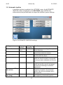
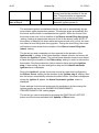
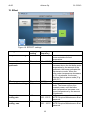
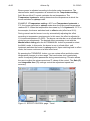
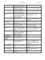
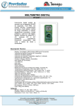
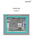
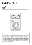
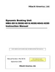
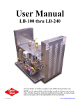
ARITERM OY
Arimatic 151
User manual
v2.00
Ariterm Oy
21.5.2013
Contents
1. General ......................................................................................................................... 3
2. Transport, storage and package opening ...................................................................... 3
3. Warranty........................................................................................................................ 3
4. Installation and commissioning ..................................................................................... 4
5. System description ........................................................................................................ 5
6. Operating the system .................................................................................................... 6
7. Main pages .................................................................................................................... 7
7.1 MAIN PAGE ............................................................................................................... 7
7.2 ALARMS -page .......................................................................................................... 8
7.3 SETTINGS -page ....................................................................................................... 9
7.4 OPERATION -page .................................................................................................. 10
8. Options ........................................................................................................................ 13
9. Time and date ............................................................................................................. 14
10. Language ..................................................................................................................... 14
11. Ignition ......................................................................................................................... 15
11.1 Automatic ignition ................................................................................................... 17
12. Effect............................................................................................................................ 19
13. Effect settings .............................................................................................................. 21
13.1 Feeding auger settings ........................................................................................... 21
13.2 Primary fan settings ................................................................................................ 22
13.3 Secondary fan settings ........................................................................................... 23
14. Factory settings ........................................................................................................... 23
14.1 Pellet auger ............................................................................................................ 24
14.2 Pellet feeder PS10 (250-400kW) ............................................................................ 25
14.3 Wood chip auger .................................................................................................... 26
15. Storage auger settings ................................................................................................. 27
16. Smoke gas fan ............................................................................................................. 28
17. Accessories ................................................................................................................. 29
17.1 Bar discharger ........................................................................................................ 29
1
v2.00
Ariterm Oy
21.5.2013
17.2 Sweeping settings .................................................................................................. 30
17.3 Pulse extinguishing ................................................................................................ 31
17.4 Residual oxygen-control ......................................................................................... 32
17.5. Ash screws ............................................................................................................ 34
17.6 MultiJet control ....................................................................................................... 35
17.7 Shunt control (Heating circuit control) .................................................................... 36
17.8 Smoke gas temperature ......................................................................................... 38
17.9 Buffer tank control .................................................................................................. 38
17.10 GSM alarms ......................................................................................................... 40
18. Troubleshooting ........................................................................................................... 40
2
v2.00
Ariterm Oy
21.5.2013
1. General
Arimatic 151 control centre is designed to control 40-150kW bio heating
systems supplied by Ariterm Oy. The centre is suitable for controlling the
HakeJet, BioJet and MultiJet burners and the BioComp boiler. There are
several options available for the control centre, including ash auger control ,
residual oxygen (Lambda sensor) and GSM alarms.
The system is controlled with programmable logic (Siemens S7-1200). The
interface is a 4.3" graphic touch screen display. Arimatic 151 system burners
use energy-efficient and easy to adjust EC combustion air blowers.
2. Transport, storage and package opening
The centre is delivered with a platform. The package should be opened as
close to the installation site as possible. The centre should be stored indoors.
It is important that the recipient check the condition of the centre before
reception. In case of damage, the dealer must be contacted without delay.
It is important to inspect the contents of the centre after opening the package.
Sensors included in the centre are delivered in a separate package with other
equipment. Inspect the sensors by consulting the part list delivered with the
package.
3. Warranty
Ariterm provides a one-year warranty for its equipment. The warranty is valid
for one year starting from the date of implementation or for maximum of 18
months from the date of delivery.
The warranty covers craftsmanship and material defects. Ariterm Oy will
deliver new replacement parts for defective parts free of charge.
Spare parts are provided with a 12-month warranty.
The warranty does not cover damages resulting from incorrect installation or
thunder.
3
v2.00
Ariterm Oy
21.5.2013
4. Installation and commissioning
Install the centre in a place where the system is easy to use and cables are
easy to install. The centre should have 1 m of space in front of it.
Electrical connections should be done according to the wiring diagrams. The
wiring diagrams also indicate accessories. If no safety devices are connected
to the system, the respective terminal block should be short-circuited.
Example: Dry-boiling protection is not required for systems under 100kW. If
there is no dry-boiling protection, a permanent loop should be installed
between terminal blocks 10X1: 24 V DC and 41.
Current limits for the thermal overload relays and motor protectors should be
set according to the current value consumed by the motor. The current values
are indicated in the type plate of the motor.
The centre can be started once all electrical connections are completed. By
accessing the OPTIONS -menu from the SETTINGS -page, you can configure
system devices, such as Ash screw 1. Do not select functions/devices not
included in the system, because they may cause unnecessary alarms. NOTE!
The OPTIONS -menu can be accessed with Maintenance -level codes.
After completing system configuration, check the system for any alarms
caused by, for example, uninstalled or incorrectly connected sensors.
Functionality of all safety devices, such as emergency stop buttons,
thermostats and hatch switches must be tested/checked.
Then, check the rotation directions of screws and test all functions (fans,
screws/augers) in the MANUAL -menu.
The system has factory default settings, but certain settings, such as the
EFFECT -settings should be adjusted according to the fuel (Check chapter
14). Adjustments should be made by means of a flue gas analyser in order to
ensure clean combustion. Additionally the STORAGE AUGER -settings must
be adjusted based on the size of the funnel between the feeding auger and
the storage auger.
NOTE! If the system is equipped with automatic ignition, the AUTOMATIC
IGNITION -settings must always be defined case-specifically. The settings
should be made by an authorised maintenance professional during
commissioning. Incorrect ignition times and settings may result in a failed
ignition and halt the system.
4
v2.00
Ariterm Oy
21.5.2013
5. System description
NOT IN USE (STOP
mode)
- pumps are running
- flue gas fan is on
ALARM
For example,
Emergency stop or
flame detection.
SHUTDOWN
- by the user
- Buffer tank
control (automatic
start-up)
AUTOMATIC
No flame
Flame
IGNITION 1
1. Fanning
2. Funnel filling
3. Ignition load
4. Ignition
Flame
IGNITION 2
Constant voltage
EFFECT MODE
21-100% power
Boiler temperature > Setting
+hysteresis
Boiler temperature < Setting +0.5 x hysteresis
UPKEEPING
Ember
maintenance
The system is started with the AUTOMATIC -button, after which the ignition
pages open. If the flame detection system detects a flame in the burner head,
the burner switches to effect mode. After the ignition phase, the burner
switches to effect mode, during which the effect of the burner is adjusted
according to the required heating power. The automatic system attempts to
maintain the boiler water temperature at the set level. If a high level of heating
is not required, but the boiler water temperature increases excessively, the
burner will activate the upkeeping mode.
The burner uses the upkeeping mode to maintain ember in the burner head.
When the boiler water temperature decreases, the burner returns to the effect
mode. The user can stop storage operation and empty the burner screw by
5
v2.00
Ariterm Oy
21.5.2013
pressing the SHUTDOWN -button. This function is used, for example during
maintenance.
STOP -button stops the system immediately. Only the pumps and the smoke
gas fan remain in operation. These operations must be stopped manually.
In buffer tank use, the shutdown function is activated automatically, when the
lower temperature of the buffer tank exceeds its setting (e.g. 80°C). Automatic
ignition starts when the buffer tank temperature decreases below its setting
(e.g. 60°C).
Alarms are indicated with a red blinking light appearing on the display. The
ALARMS -page indicates the reason for the alarm and its time. You can
acknowledge alarms and review the alarm history.
6. Operating the system
The graphic interface makes it easy to control the system. The interface
contains four main pages: MAINPAGE, ALARMS, SETTINGS and
OPERATION. You can navigate the pages with the button located on the
bottom of the display.
MAIN PAGE
page
ALARMS
SHUNT
SETTINGS
BUFFER TANK
OPERATION
page
6
v2.00
Ariterm Oy
21.5.2013
The MAINPAGE displays the operation of the system. The page contains, for
example, temperature, blower power and the operation of the feeding auger.
The ALARMS -page displays active error notifications. You can also
acknowledge alarms and review the alarm history here.
The SETTINGS -page contains the settings menus where you can adjust the
parameters of various functions. The menus displayed are determined
according to the features activated in the OPTIONS -menu.
The system is operated from the OPERATION -page. The user can perform
operations manually, set the system run them automatically or stop the
system. The page also includes, for example, pump operations.
The system has two password-protected user levels: USER and
MAINTENANCE. The USER levels restrict access to all settings, preventing
unauthorised users from adjusting the settings. The USER level user name is
user and the password is user.
The MAINTENANCE level is for authorised maintenance professionals,
restricting access to, for example, sensor scaling settings, PID parameters
and OPTIONS-menu.
7. Main pages
7.1 MAIN PAGE
Figure 1. MAIN PAGE - burner in STOP mode.
The interface MAINPAGE contains the following items:
7
v2.00
Ariterm Oy
21.5.2013
- Burner mode (EFFECT MODE,UPKEEP, MANUAL, STOP)
- Boiler water temperature
- Effect percentage at which the burner is currently run
- Primary and secondary fan power
- Smoke gas fan power
- Operation of burner screw
- Operation of storage auger
- Funnel surface level sensor status
- Flame detection information
- Underpressure of combustion chambers
- Residual oxygen (if option is activated)
- Burner screw temperature (if option is activated)
- Bar discharger (if option is activated)
- Silo lower limit (if option is activated)
- Time and date.
System settings cannot be adjusted on the MAINPAGE. Settings can be
adjusted on the OPERATION -page.
7.2 ALARMS -page
Figure 2. ALARMS -page
Alarms are indicated with a red blinking light appearing on the display and the
system goes into Stop-mode. The ALARMS page displays active alarms
8
v2.00
Ariterm Oy
21.5.2013
(State), time (Active Time) and the reason for the alarm (Text). The source of
the alarm must be removed before the alarm can be acknowledged (Ack All
button). The alarms are recorded in the alarm history, which can be reset with
the Clear button.
The system must be restarted with the AUTOMATIC -button after
acknowledging alarms.
7.3 SETTINGS -page
Figure 3. SETTINGS page - all options selected.
The SETTINGS -page contains the settings menus where you can adjust the
parameters/settings of various functions. The menus displayed are
determined according to the features activated in the OPTIONS -menu.
The following menus are always displayed: EFFECT,BURNER SCREW,
STORAGE AUGER, PRIMARY FAN, SECONDARY FAN, SMOKE GAS FAN,
LANGUAGE and OPTIONS.
9
v2.00
Ariterm Oy
21.5.2013
7.4 OPERATION -page
Figure 4. OPERATION page - System in STOP mode.
The system is operated from the OPERATION -page. When the system is
stopped (STOP), the AUTOMATIC, MANUAL and STOP buttons are
displayed. The upper field indicates system status "STOP". When the system
is in the Automatic mode (burner in effect mode), the SWEEPING and
SHUTDOWN -buttons appear instead of the MANUAL -button.
If the Sweeping and Ash screw options are selected, their operating buttons
are displayed. These buttons can be used to override their scheduled
operation.
The system is stopped with the STOP -button. However, the cooling pump
and the smoke gas fan must be stopped with their dedicated buttons.
10
v2.00
Ariterm Oy
21.5.2013
MANUAL MODE
It is necessary to run the system manually during commissioning or, for
example, maintenance. If the user opens the manual operation page during
automatic operation (NOTE! STOP -button must be pressed first), the smoke
fan and pumps remain in operation. The following functions are controlled
here:
- Burner screw
- Storage auger
- Primary fan power adjustment
- Secondary fan power adjustment
- Smoke gas fan power adjustment
- Bar discharger system
- Ash screws
- Moving grate
- BACKWARD -button for reversing the screws/augers.
- Sweeping
- Cooling pump
- Hot air gun
NOTE! The buttons displayed on the MANUAL -page depend on settings
made (selected functions) on the OPTIONS -page.
Figure 5. Manual -page
11
v2.00
Ariterm Oy
21.5.2013
AUTOMATIC
If the burner is set to Automatic mode, the burner will activate the Effect mode, when the flame detection system detects a flame. Burner effect is
adjusted on a scale of 20-100%. If the flame detection does not detect a
flame, the system activates the controlled ignition phase (see section 11.
Ignition)
SHUTDOWN
This function stops the storage system operation and the funnel is no longer
filled. The system continues to operate as long as the burner screw and funnel
contain fuel. The operation stops, when the Alarm! Flame alarm is displayed.
The function can be used, for example, during preparations for boiler and
burner maintenance.
In buffer tank use, the shutdown function is activated automatically, when the
lower temperature of the buffer tank exceeds its setting. The burner will
remain in standby mode. The start-up command is given when the buffer tank
upper temperature falls below the set temperature.
STOP
This button stops all devices of the system, except for the cooling pump and
the smoke gas fan which must be stopped with their dedicated buttons.
SWEEPING
This button controls the convection sweeping motor, overriding their
scheduled functions.
ASH SCREW
This button controls the ash screws, overriding their scheduled functions.
12
v2.00
Ariterm Oy
21.5.2013
8. Options
All features/accessories of the system are configured in the OPTIONS -menu
during commissioning. Example: The woodchip system consists of the
hydraulic storage T1, MultiJet 60kW burner, pulse extinguishing system and
residual oxygen measurement. When using the system, the bar discharger,
moving grate, pulse extinguishing system and O2-control must be enabled in
the OPTIONS -menu. Then, the settings menus of the functions appear on the
SETTINGS -page.
NOTE! Make sure that unconnected options are not enabled. Otherwise they
may cause unnecessary alarms.
Available options:
1. Burner screw temperature
2. Pulse extinguishing
3. Burners cooling pump (BioJet)
4. Shunt control (Heating circuit control)
5. Bar discharger
6. Ash screw 1
7. O2-control
8. Smoke gas temperature
9. Sweeping
10. Ash screw 2
11. Moving grate (MultiJet)
12. Automatic ignition
13. Buffer tank
14. GSM (SMS alarms)
13
v2.00
Ariterm Oy
21.5.2013
Figure 6. OPTIONS -page
9. Time and date
Settings are displayed on the top left corner of the MAIN PAGE. You can
adjust time and date by pressing the respective button.
10. Language
You can select the OSD language by pressing a flag on the SETTINS -page.
14
v2.00
Ariterm Oy
21.5.2013
11. Ignition
If the AUTOMATIC -button is pressed on the OPERATION -page, the smoke
gas fan ventilates the boiler (2 min). If the flame detection does not detect a
flame, the user can select the Automatic or Manual ignition (NOTE!
automatic ignition is an accessory).
Figure 7. Ignition selection
MANUAL IGNITION
With the manual ignition, the user can manually run the burner screw or switch
on the primary or secondary fan.
If the automatic ignition option is enabled, the HOT AIR GUN -button will also
be displayed. The ignition can also be used for manual ignition.
15
v2.00
Ariterm Oy
21.5.2013
Figure 8. Manual ignition -page - Burner equipped with automatic ignition.
Run the burner auger with the BURNER SCREW -button so that the burner
head has enough fuel. The storage auger automatically fills the funnel while
the smoke gas fan maintains an underpressure in the combustion chamber.
Ignite the fuel and turn on combustion air fans. Wait for the fuel to properly
ignite. You can add more fuel to the burner head. When the flame is large
enough, the Ignition 1 -phase can be acknowledged with the MANUAL
IGNITION 2 -button, after which the system will proceed to the Ignition 2 phase.
During the Ignition 2 -phase, the burner is run at a fixed effect level, which the
user can adjust. In this case, the fuel feed and fanning is controlled
automatically. NOTE! During the first heating process, the burner should
be run at low power (21-30%) for approximately one hour in order to
remove humidity from the burner ceramics. When the flame detection
detects a flame, a flame symbol will be displayed . Then you can activate
automatic effect adjustment by pressing the MAN. IGNITION READY -button.
You do not need to wait for the flame information. The Ignition 2 can be
acknowledged earlier as well.
The flame information is provided by the flame detection thermostat
measuring the temperature of smoke gas. When the smoke gas temperature
exceeds the thermostat limit (approximately 70°C), the flame information is
displayed. The flame detection phase (10 min.) is activated after the Ignition
2 -phase. During this phase, the smoke gas temperature increases over the
set temperature.
If the system is equipped with automatic ignition, the flame data is monitored
during the ignition with an optical flame detection sensor.
16
v2.00
Ariterm Oy
21.5.2013
11.1 Automatic ignition
If automatic ignition is enabled in the OPTIONS -menu, the AUTOMATIC
IGNITION -menu is displayed on the SETTINGS -page. NOTE! Only
authorised service professionals can adjust the automatic ignition settings.
Figure 9. AUTOMATIC IGNITION -settings
Setting
Setting
frequency
0-100%
Flame limit
Factory
setting
True
value
5%
Flame delay
30s
0-360s
Ignition step 1
240s
0-600s
Ignition step 2
600s
0-1200s
Burner screw filling
time (short)
20s
0-360s
Burner screw filling
time (long)
20s
0-600s
Flame value
0-100%
17
Function
Displays the true reading of the optical
flame detection.
Flame detection limit value for the
optical flame detection sensor.
Delay during which the flame detection
should detect the flame.
Length of the Ignition 1 -phase, during
which the flame should be recognised.
Hot air gun and combustion air fans are
on.
Length of the Ignition 2 -phase, during
which the burner runs at a set power
level before switching to automatic
adjustment.
If the burner screw is full in the
beginning of ignition, the automatic
ignition can also be initialised with a
short ignition.
The burner screw should be empty in
the beginning of automatic ignition.
v2.00
Ariterm Oy
Hot air gun running
time at step 2
30s
21.5.2013
Then, the burner screw feeds fuel to the
burner head for the duration of the set
time. There should be an appropriate
amount of fuel in the burner head.
Hot air gun operation time after flame
detection (ignition phase 2).
0-360s
The automatic ignition is initialised either by the user or automatically by the
accumulator upper temperature sensor. The storage auger automatically fills
the funnel and the boiler is ventilated before ignition. When the funnel is full,
the burne screw runs for the duration of the Burner screw filling time (long)
-setting, feeding an appropriate amount of fuel to the burner head. NOTE! If
the system is halted by an alarm while the burner screw is full of fuel, the user
can select a short filling time during ignition. During the short filling, the screw
will feed the burner head for the duration of the Burner screw filling time
(short) -setting.
The hot air gun and combustion air fans operate for the duration of the
Ignition step 1 -setting. If the flame detection detects a flame, the burner will
activate the Ignition 2 -phase. The optical flame detection sensor must detect
a flame during the duration of the Flame delay -setting in order to activate the
flame data. If the flame detection fails to detect a flame during the Ignition
step 1 -time setting, the fans and ignition stop and the Alarm! automatic
ignition alarm is displayed.
During the Ignition 2 -phase, the burner runs at a power level configured in
the Burner screw -setting for the duration of the Ignition step 2 -setting. After
this the burner automatically activates the effect mode. If the flame disappears
during the Ignition 2 -phase, the Alarm! Automatic ignition -alarm is
displayed.
Power settings for the burner screw and the combustion air fans during the
ignition phases are set in the BURNER SCREW/PRIMARY
FAN/SECONDARY FAN -setting pages.
The hot air gun can be activated by pressing the IGNITION UP->EFFECT button once the burner switches from Upkeep to Effect mode.
18
v2.00
Ariterm Oy
21.5.2013
12. Effect
Figure 10. EFFECT -settings
Setting
Temperature setting
Factory
setting
80°C
Measured temperature
Temperature
hysteresis
True value
5°C
Effect
Manual effect setting
True value
21%
Temperature sensor
scaling min
-10
Temperature sensor
scaling max
150
Setting
frequency
0-100°C
Function
Set boiler water temperature. The
burner maintains the set
temperature.
-10…150°C True boiler water temperature.
0-50°C
If the boiler water temperature
increases above the set boiler water
temperature by the amount of the
hysteresis, the burner activates the
maintenance mode. When the
boiler water temperature decreases
by 0.5 x hysteresis, the burner
switches back to power mode (E.g.
at 82.5°C)
0-100%
True burner power
20-100%
Burner power in manual operation
mode. The burner will run at a
constant power, until the boiler
water temperature increases over
the set temperature by the amount
of hysteresis.
Boiler water temperature scaling.
150...150°C NOTE! Requires Maintenance level
password.
Boiler water temperature scaling.
150…150°C NOTE! Requires Maintenance level
password.
19
v2.00
Ariterm Oy
21.5.2013
Burner power is adjusted according to the boiler water temperature. The
desired boiler water temperature is entered into the Temperature setting field. Burner effect PI control maintains the set temperature. The
Temperature hysteresis -setting determines the temperature at which the
burner switches to upkeep mode.
EXAMPLE: if Temperature setting = 80°C and Temperature hysteresis =
5°C, the burner switches to upkeep mode when the boiler water temperature
reaches 85°C. When the temperature decreases by 0.5 x Hysteresis, 2.5°C in
the example, the burner switches back to effect mode (effect level 21%).
During normal use the burner is run by automatically adjusting the effect
according to temperature requirements. In this case, the effect is adjusted in
1% increments between 20-100%. The burner can also be run at a fixed effect
during burner adjustments. The desired effect percentage is set with the
Manual effect setting after the AUTO/MANUAL -button is pressed to select
the MAN -mode. In this mode, the burner is run at a fixed effect, until
hysteresis switches the burner to upkeep mode. Upon switching back to effect
mode, the burner continues at a fixed effect level.
By pressing the TREND/PID -button, you can review effect and boiler water
temperature changes in a time range. The trend review tool is particularly
useful for adjusting effect parameters during commissioning. This also allows
the user to adjust the enhancement and Ti values of the control. The Gain (P)
and Integration time (Ti) -settings control the adjustment speed and
accuracy.
Figure 11. EFFECT CONTROL page - Trend.
20
v2.00
Ariterm Oy
21.5.2013
13. Effect settings
The control system adjusts the burner effect by controlling the fuel feed
(burner screw pulse and pause time ratio) and the rotation speed of the
primary and secondary fans according to heat load changes.
The programme has 80 effect levels (upkeep mode 20%, effect mode 21100%). The SETTINGS -page contains the BURNER SCREW, PRIMARY
FAN and SECONDARY FAN -menus for setting the speed of the burner screw
and the rotation speed of the primary and secondary fan (0-100%) in five
power levels: UP, 21%, 50%, 75% and 100%. The programme calculates
intermediate power levels according to these basic settings (e.g. 22, 23,
24…%).
13.1 Burnerscrew settings
Figure 12. BURNER SCREW settings.
Effect point
UP
Factory
setting
0.5%
21%
50%
75%
100%
Ignition
2.0%
5.0%
8.0%
10.0%
5%
Backfire
240s
Setting
Function
frequency
0-100%
Burner screw power in upkeep
mode.
0-100%
Burner screw power at 21%.
0-100%
Burner screw power at 50%.
0-100%
Burner screw power at 75%.
0-100%
Burner screw power at 100%.
0-100%
Burner screw power during Ignition 2
phase.
0-600s
Burner screw operating time when
back fire thermostat is set off. The
Burner screw should be emptied
during this time. The storage stops.
21
v2.00
Ariterm Oy
21.5.2013
The Burner screw power is indicated in percentages. The system calculates
the running and pause times automatically according to the effect percentage.
For example, "Power-% = 10%" indicates a running time of 1s and pause time
of 9s. The system calculates the intermediary power percentage
automatically. See factory settings in section 12.4.
You must enter the user password in order to adjust the BURNER SCREW settings.
13.2 Primary fan settings
Figure 13. PRIMARY FAN -settings
Power point
UP
21%
50%
75%
100%
Ignition
Factory
setting
0.0%
25%
35%
50%
70%
20%
Setting
frequency
0-100%
0-100%
0-100%
0-100%
0-100%
0-100%
Function
Primary fan power in upkeep mode.
Primary fan power at 21%.
Primary fan power at 50%.
Primary fan power at 75%.
Primary fan power at 100%.
Primary fan power during Ignition 2
phase.
The primary fan power is determined between 0-100% for each effect point of
the chart. The system calculates the intermediary power percentage
automatically. The primary fan fans combustion air from underneath the fuel,
gassing the fuel. See factory settings in section 12.4.
You must enter the user password in order to adjust the PRIMARY FAN settings.
22
v2.00
Ariterm Oy
21.5.2013
13.3 Secondary fan settings
Figure 14. SECONDARY FAN -settings
Power point
UP
21%
50%
75%
100%
Ignition
Factory
setting
0.0%
Setting
Function
frequency
0-100%
Secondary fan power in upkeep
mode.
15%
0-100%
Secondary fan power at 21%.
30%
0-100%
Secondary fan power at 50%.
45%
0-100%
Secondary fan power at 75%.
65%
0-100%
Secondary fan power at 100%.
10%
0-100%
Secondary fan power during Ignition
2 phase.
The primary fan power is determined between 0-100% for each effect point of
the chart. The system calculates the intermediary power percentage
automatically. The secondary fan fans combustion air from above the fuel,
burning the gassed fuel. See factory settings in section 12.4.
You must enter the user password in order to adjust the SECONDARY FAN settings.
14. Factory settings
Consult the following charts for making adjustments. Combustion air fan
power adjustments should be made by means of a flue gas analyser in order
to ensure clean, efficient combustion. According to user experiences, the
maintenance mode settings in particular require certain initial adjustments.
23
v2.00
Ariterm Oy
21.5.2013
14.1 Pellet auger
Burner screw diameter 114mm, bore diameter 95mm, auger elevation angle
20°, rotation speed 19rpm. Auger production 291.6kg/h, corresponding to
1260kW (pellet energy 4.8kWh/kg, boiler efficiency 90%).
Effect
Upkeep
21%
50%
75%
100%
Effect
Upkeep
21%
50%
75%
100%
Effect
Upkeep
21%
50%
75%
100%
Effect
Upkeep
21%
50%
75%
100%
Effect
Upkeep
21%
50%
75%
100%
Power
kW
6kW
9kW
20kW
30kW
40kW
40kW system
Burner
Primary fan Secondary
screw
fan
0.5
0%
0%
0.7
20%
15%
1.6
30%
25%
2.4
40%
40%
3.2
50%
55%
Power
kW
6kW
12kW
30kW
45kW
60kW
60kW system
Burner
Primary fan Secondary
screw
fan
0.5
0%
0%
0.9
25%
15%
2.4
40%
35%
3.6
55%
45%
4.8
60%
65%
Power
kW
8kW
17kW
40kW
60kW
80kW
80kW system
Burner
Primary fan
screw
0.6
0%
1.3
30%
3.2
50%
4.8
60%
6.3
65%
Secondary
fan
0%
20%
45%
60%
65%
Power
kW
12kW
25kW
60kW
90kW
120kW
120kW system
Burner
Primary fan
screw
0.9
0%
2.0
35%
4.8
50%
7.1
65%
9.5
70%
Secondary
fan
0%
20%
45%
60%
55%
150kW system
Power
Burner
Primary
kW
screw
blower
15kW
1.2
0%
30kW
2.4
35%
75kW
6.0
50%
110kW
8.7
65%
150kW
12.0
80%
24
Secondary
blower
0%
20%
45%
60%
75%
v2.00
Ariterm Oy
21.5.2013
14.2 Pellet feeder PS10 (250-400kW)
Pellet feeder production (250kW-400kW) is approximately 250kW at 50Hz
(efficiency 90%).
Effect
Upkeep
21%
50%
75%
100%
Effect
Upkeep
21%
50%
75%
100%
Effect
Upkeep
21%
50%
75%
100%
Effect
Upkeep
21%
50%
75%
100%
Effect
Upkeep
21%
50%
75%
100%
40kW system, PS10 250-400kW
Power
Burner
Primary fan
kW
screw
6kW
2.5
0%
9kW
3.7
20%
20kW
8.2
30%
30kW
12.3
40%
40kW
16.5
50%
Secondary
fan
0%
15%
25%
40%
55%
60kW system, PS10 250-400kW
Power
Burner
Primary fan
kW
screw
6kW
2.5
0%
12kW
5.0
25%
30kW
12.3
40%
45kW
18.5
55%
60kW
33.0
60%
Secondary
fan
0%
15%
35%
45%
65%
80kW system, PS10 250-400kW
Power
Burner
Primary fan
kW
screw
8kW
3.3
0%
17kW
7.0
30%
40kW
16.5
50%
60kW
24.7
60%
80kW
33.0
65%
Secondary
fan
0%
20%
45%
60%
65%
120kW system, PS10 250-400kW
Power
Burner
Primary fan
kW
screw
12kW
4.9
0%
25kW
10.3
35%
60kW
24.7
50%
90kW
37.1
65%
120kW
49.5
70%
Secondary
fan
0%
20%
45%
60%
55%
150kW system, PS10 250-400kW
Power
Burner
Primary fan
kW
screw
15kW
6.2
0%
30kW
12.3
35%
75kW
30.9
50%
110kW
45.3
65%
150kW
61.8
80%
Secondary
fan
0%
20%
45%
60%
75%
25
v2.00
Ariterm Oy
21.5.2013
14.3 Wood chip auger
Burner screw diameter 159mm, bore diameter 135mm, auger elevation angle
20° rotation speed 11.5rpm. Auger production 0.486m3/h, corresponding to
317kW (chip 750kWh/m3, boiler efficiency 87%).
Effect
Upkeep
21%
50%
75%
100%
Effect
Upkeep
21%
50%
75%
100%
Effect
Upkeep
21%
50%
75%
100%
Effect
Upkeep
21%
50%
75%
100%
Effect
Upkeep
21%
50%
75%
100%
Power
kW
9kW
20kW
30kW
40kW
Power
kW
12kW
30kW
45kW
60kW
Power
kW
17kW
40kW
60kW
80kW
Power
kW
25kW
60kW
90kW
120kW
Power
kW
30kW
75kW
110kW
150kW
40kW system
Burner
Primary fan
screw
0.5
0%
2.8
20%
6.3
30%
9.5
40%
12.6
50%
Secondary
fan
0%
15%
25%
40%
55%
60kW system
Burner
Primary fan
screw
0.5
0%
3.7
25%
9.4
40%
14.1
55%
19.0
60%
Secondary
fan
0%
15%
35%
45%
65%
80kW system
Burner
Primary fan
screw
0.5
0%
5.4
30%
12.6
50%
19.0
60%
25.2
65%
Secondary
fan
0%
20%
45%
60%
65%
120kW system
Burner
Primary fan
screw
0.5
0%
7.9
35%
19.0
50%
28.3
65%
37.8
70%
Secondary
fan
0%
20%
45%
60%
55%
150kW system
Burner
Primary fan
screw
0.5
0%
9.4
35%
23.6
50%
34.7
65%
47.3
80%
Secondary
fan
0%
20%
45%
60%
75%
26
v2.00
Ariterm Oy
21.5.2013
15. Storage auger settings
Figure 15. STORAGE AUGER settings
Setting
Funnel's emptying time
Factory
setting
15s
Setting
frequency
0-60s
Storage alarm time delay
600s
0-1200s
Inactive sensor level for
burner screw
150s
0-600s
Funnel's force filling
time
2s
0-60s
27
Function
When the funnel photocell pair no
longer detects fuel in the funnel,
the total operating pulse time of the
burner screw is calculated. When
the set time is reached, the storage
auger is activated. The settings
define the lower limit of the funnel.
When the photocell pair detects
fuel, the storage auger stops.
When the storage auger has run
for the set time, but the funnel
photocell pair fails to detect the
surface of the fuel, the system
indicates the Alarm! Fuel low
alarm.
If the funnel photocell pair detects
fuel during the set time (calculated
with the feeder auger pulses), the
storage auger is activated for the
set duration. The purpose here is
to remove any splinters blocking
the sensor. NOTE! Settings are
displayed if the bar discharger
option was selected.
Storage auger running time after
the forced filling delay.
v2.00
Ariterm Oy
21.5.2013
Photocell pair located in the funnel measures the fuel level. When the funnel
photocell pair no longer detects fuel in the funnel, the total operating pulse
time of the burner screw is calculated. When the Funnel's emptying time setting is reached, the storage auger is activated. Time should be set so that
there is always fuel on top of the burner screw. For example, too long time
setting may result in a lack of fuel in the burner screw, which subsequently
hinders combustion.
The storage auger fills the funnel, until the photocell pair detects it, stopping
the storage auger. When the storage auger has run for the duration of the
Storage alarm time delay -setting, but the funnel photocell pair fails to detect
the surface of the fuel, the system indicates the Alarm! Fuel -alarm.
If the photocell pair detects fuel according to the configuration of the
Tikkuviive setting (calculated with the burner screw pulses), the storage
auger is activated for the duration of the Inactive sensor level for burner
screw -setting. This may occur, for example, when a splinter is wedged
between the sensors. If the splinter is not removed, the system will indicate
the Alarm! Jam -alarm.
16. Smoke gas fan
Figure 16. SMOKE GAS FAN settings
Setting
Measured pressure
Underpressure at
upkeeping
Factory
setting
True
value
10Pa
Setting
frequency
-100…100Pa
0-100Pa
28
Function
True underpressure in the
combustion chamber.
Underpressure setting when
burner is in upkeep mode.
v2.00
Ariterm Oy
Underpressure at effect
run
Underpressure alarm
limit
25Pa
21.5.2013
0-100Pa
Underpressure setting when
burner is in effect mode.
-20Pa
-100…0Pa
Combustion chambers
overpressure limit reached,
followed by "Alarm! Smoke gas
fan". NOTE! Limits should be set
with a negative marker (-).
Underpressure scaling
-100Pa
-100…100Pa Pressure sensor scaling. NOTE!
min.
Requires Maintenance level
password.
Underpressure scaling
100Pa
-100…100Pa Pressure sensor scaling. NOTE!
max.
Requires Maintenance level
password.
The speed of the smoke gas fan is regulated according to the underpressure
of the combustion chamber. Underpressure can be set for the Upkeep and
Effect modes.
By pressing the TREND/PID -button, you can review the smoke gas fan
adjustments. The underpressure should remain approximately same as the
set value. If the smoke gas fan adjustment wavers, its speed can be adjusted
with the Gain (P) and Integration time (Ti) -settings.
17. Accessories
17.1 Bar discharger
Figure 17. BAR DISCHARGER settings.
Start delay
120s
0-360s
29
When the storage auger has run
v2.00
Ariterm Oy
21.5.2013
for the set time, but the funnel
sensor has not detected any fuel,
the bar discharger is activated for
the set duration.
Running time
10s
0-60s
Bar discharger operating time.
If BAR DISCHARGER is selected in the OPTIONS -menu, the SETTINGS page will also display the BAR DISCHARGER -settings. When the storage
auger has run for the set Start delay -time, but the funnel sensor has not
detected any fuel, the bar discharger is activated for the set duration. The bar
discharger runs for the duration of the Running time -setting. Time should be
set so that the cylinder performs one reciprocating motion at most.
17.2 Sweeping settings
Figure 18. SWEEPING settings
Setting
Running time
(minutes)
Pause time
(minutes)
Factory
setting
4 min
Setting
frequency
0-60 min
Function
60 min
0-60 min
Sweeping pause duration.
Sweeping duration
The sweeping motor moves spirals inside the convection pipes in a
reciprocating, horizontal motion. The sweeping motor is run for a set time
(Running time -setting) in set intervals (Pause time -setting). NOTE! The
boiler should also be swept manually. See boiler instructions.
30
v2.00
Ariterm Oy
21.5.2013
17.3 Pulse extinguishing
Figure 19. PULSE EXTINGUISHING settings.
Setting
Burner screw
temperature
Temp. limit
(back fire)
Temperature
sensor scaling
min.
Temperature
sensor scaling
min.
Level 1
temperature
Level 1
Extinguishing
pulse
Level1 Pause
time
Level 2
Temperature
Level 2
Extinguishing
pulse
Level2 Pause
time
Factory
setting
True value
Setting
frequency
0-150°C
Function
80°C
0-150°C
0°C
0-150°C
If the burner screw surface temperature
exceeds the set temperature, the system
reacts similarly to when a back fire
thermostat is set off.
Temperature sensor scaling. NOTE!
Requires Maintenance level password.
150°C
0-150°C
Temperature sensor scaling. NOTE!
Requires Maintenance level password.
50°C
0-150°C
1s
0-10s
Feeding auger temperature at which pulse
shutdown level 1 humidification starts.
Level1 pulse length.
60s
0-360s
Level1 Pause time
60°C
0-150°C
2s
0-10s
Feeding auger temperature at which pulse
shutdown level 2 humidification starts.
Level 2 pulse length.
30s
0-360s
Level2 Pause time
Burner screw surface temperature
31
v2.00
Ariterm Oy
21.5.2013
The system can be equipped with a pulse extinguishing system for preventing
back fires by humidifying fuel with water when the auger surface temperature
increases. There are two humidification temperatures. Pulse extinguishing
utilises a Pt100 sensor, which measures the burner screw temperature, and a
magnetic valve, which controls the water supply to the burner screw.
NOTE! Water extinguishing system cannot be used with pellets.
When the burner screw surface temperature exceeds the Level 1
temperature -setting, the magnetic valve is controlled according to the Level
1 Extinguishing pulse and the Level1 Pause time -settings. Pulses are
continued until the temperature falls below the setting. If the temperature
keeps rising, the system will switch to the faster level 2 pulses. If the burner
screw surface temperature exceeds the Temp. limit (back fire) -setting, the
burner will react similarly to when a back fire thermostat is set off.
SMS alarms can be activated with the LEVEL 1/2 ALARM NOT IN USE buttons.
17.4 Residual oxygen-control
Figure 20. O2-CONTROL settings.
Setting
O2 set point
Measured O2
O2 alarm limit
O2-control
minimum
O2-control
maximum
Factory
setting
8.0%
True value
4.0%
-5.0%
Setting
frequency
6.0-15.0%
0-25%
0-8.0%
0..-50%
15.0%
0-50%
32
Function
Residual oxygen target value
Residual oxygen true value
Residual oxygen alarm limit.
Secondary fan maximum power
reduction.
Secondary fan maximum power
increase.
v2.00
Ariterm Oy
21.5.2013
The residual oxygen content of the flue gas is measured with a lambda sensor
(accessory). The O2 CONTROL NOT IN USE -button determines whether the
measured value is applied to the secondary fan power or just displayed as a
residual oxygen value. The required oxygen limit is configured in the O2 set
point -setting. The recommended residual oxygen level is approximately 78%. The residual oxygen value can also be viewed on the MAIN PAGE. When
the residual oxygen measurement is enabled, it controls the operation of the
secondary fan. The correction percentage is displayed on the right.
The O2-control minimum- and O2-control maximum -settings determine
how much the oxygen measurement impacts the secondary fan control. The
limits are meant to prevent the secondary fan from being halted due to small
values and to prevent high fan speeds in case dirt accumulates on the sensor.
Figure 21. Oxygen regulator trend
By pressing the TRENDI/PID -button, you can monitor the residual oxygen
values. This also allows the user to adjust the enhancement and Ti values of
the control. The Gain (P) and Integration (Ti) settings (integration) control the
adjustment speed and accuracy.
33
v2.00
Ariterm Oy
21.5.2013
17.5. Ash screws
Figure 22. ASH SCREWS settings.
Setting
Running time
Pause ratio
(Effect/s)
Factory
setting
240s
7,200
Setting
Function
frequency
0-600s
Ash removal duration. Ash screw 1 is
controlled with pulses while Ash screw 2
auger is controlled continuously.
0-32,000
Ash screw interval relation to the burner
effect. For example, if the burner runs
for 2h (7,200s) at 100% power, the ash
screw are activated.
Ash screws are run according to the burner effect. At higher burner effect
levels the pause is shorter than at lower burner effect levels. The Running
time -setting determines the running duration of the ash screws. The Pause
ratio determines the ash removal pause length at 100% burner effect level.
For example, if the burner runs at 50% effect, the pause is twice as long.
34
v2.00
Ariterm Oy
21.5.2013
17.6 MultiJet control
Figure 23. MOVING GRATE settings.
Effect
Upkeep
21%
50%
75%
100%
On/s
0.5s
0.5s
1s
1s
1s
Setting
Factory
setting
100pcs
Off/s
30s
25s
20s
15s
10s
Function
Grate movement pulses in upkeep mode.
Grate movement pulses at 21% effect.
Grate movement pulses at 50% effect.
Grate movement pulses at 75% effect.
Grate movement pulses at 100% effect.
Setting
Function
frequency
Short move
0-999pcs
The grate movement before performing
the cleaning movement (full range). If the
setting is 0, the grate will only perform
cleaning movements.
Max. operation
20s
0-360s
Maximum linear motor running time
time
between limit switches.
Alarm delay
30s
0-360s
If the linear actuator limit switches do not
detect any furnace movement during the
set time, the system will indicate a grate
alarm.
The grate of the MultiJet burner is moved with a linear actuator. The linear
actuator is moved with pulses which are adjusted according to the burner
effect level. The basic movement is approximately 2cm in length, taking place
around the outer midline of the linear actuator. The number of basic
movements are defined in the Short move -setting. After this the grate
35
v2.00
Ariterm Oy
21.5.2013
performs a cleaning movement, where the linear actuator moves from one end
to the other.
The grate pulses (running and pause time) is determined for five power points
which the programme uses for calculating times for other power levels.
17.7 Shunt control (Heating circuit control)
Figure 24. SHUNT CONTROL -settings.
Setting
Factory
setting
Water temperature
True
value
35°C
Water temperature
Water temperature
sensor scaling min.
-10°C
Water temperature
150°C
sensor scaling max.
Out temperature
Out temperature
sensor scaling
min.
Outdoor
temperature sensor
scaling max.
True
value
-50°C
50°C
Setting
Function
frequenc
y
Supply water temperature
0-100°C
150…15
0°C
150…15
0°C
-
Supply water temperature setting when
shunt control is in the NOT IN USE mode.
Supply water temperature sensor scaling
NOTE! Requires Maintenance level
password.
Supply water temperature sensor scaling
NOTE! Requires Maintenance level
password.
Outdoor temperature.
150…15
0°C
150…15
0°C
Outdoor temperature sensor scaling.
NOTE! Requires Maintenance level
password.
Outdoor temperature sensor scaling.
NOTE! Requires Maintenance level
password.
36
v2.00
Ariterm Oy
21.5.2013
The temperature control features an outdoor temperature sensor, supply
water temperature sensor and a 0-10V shunt valve control. The supply water
temperature can be fixed (OUT TEMPERATURE CONTROL NOT IN USE button) or set according to outdoor temperature. The heating curve can be
defined with four points, which the system uses to calculate the supply water
temperature according to outdoor temperature.
Figure 25. Trend page
Out
temperature
Water
temperature
-20°C
-5°C
5°C
20°C
35°C
30°C
25°C
20°C
This also allows the user to adjust the enhancement and Ti values of the
control. The Gain (P) and Integration time (Ti) -settings (integration) control
the adjustment speed and accuracy.
37
v2.00
Ariterm Oy
21.5.2013
17.8 Smoke gas temperature
Figure 26. SMOKE GAS TEMPERATURE settings.
The maximum smoke gas temperature, at which the system will indicate an
alarm and stop the system, is configured in the Temperature limit -setting.
The page also indicates smoke gas temperature and trend.
Smoke gas temperature is also displayed on the MAINPAGE.
17.9 Buffer tank control
Figure 27. BUFFER TANK settings.
38
v2.00
Ariterm Oy
Setting
21.5.2013
Factory
setting
True
value
True
value
80°C
Setting
frequency
0-100°C
Function
0-100°C
Buffer tank lower temperature.
0-100°C
78°C
0-50°C
60°C
0-100°C
Burner stop
temperature
80 C
0-100°C
Upper temperature
max. temperature
Temperature sensor
scaling min.
90°C
0-110°C
-10°C
Temperature sensor
scaling max
150°C
150...150°
C
150...150°
C
Boiler water temperature at which the
load pump starts.
Boiler water temperature at which the
load pump stops.
The burner is activated when the Buffer
tank upper temperature falls below the
temperature setting.
When the accumulator lower
temperature exceeds the setting, the
burner will shut down.
Buffer tank maximum upper
temperature.
Buffer tank sensor scaling. NOTE!
Requires Maintenance level password.
Upper temperature
Lower temperature
Pump start
temperature
Pump stop
temperature
Burner start
temperature
Buffer tank upper temperature.
Buffer tank sensor scaling. NOTE!
Requires Maintenance level password.
Buffer tank control features the Buffer tank upper and lower temperature
sensors and load pump control. The burner must be equipped with automatic
ignition. Buffer tank usage can be activated from the OPTIONS -menu. The
burner will begin ignition once the system is set to Automatic -mode. When
using the system for the first time you should perform a manual ignition, so
that the AUTOMATIC IGNITION -settings can be done accurately.
You can enable the BUFFER TANK CONTROL -button during the ignition.
After the ignition phase, the burner switches to effect mode. When the
temperature of the boiler water exceeds the Pump start temperature -setting,
the load pump starts loading the buffer tank.
When the buffer tank lower temperature exceeds the Burner stop
temperature -setting, the burner begins shutting down. The storage auger
stops and the burner screw is emptied, until the flame detection no longer
detects a flame. When no flame is detected, the burner is in standby mode.
The load pump stops when the boiler water temperature falls below the Pump
stop temperature -setting. When the buffer tank upper temperature falls
below the Burner start temperature -setting, automatic ignition and new
loading start.
39
v2.00
Ariterm Oy
21.5.2013
The Burner stop temperature setting should be set so that the fuel in the
burner screw does not overheat the accumulator. The boiler water
temperature setting should be set higher than the burner stopping temperature
in order to increase the burner effect.
The boiler return water should be set at 70°C with an automatic control valve
(E.g. Laddomat, ESBE Series VTC500) or a heating circuit control device.
17.10 GSM alarms
The user can define two telephone numbers where SMS alarms/warnings are
sent. The SMS PROVIDER -button allows you to enter the operator
messaging centre number. You should enter this number in case SMS alarms
are not sent.
18. Troubleshooting
Alarm messages indicate the cause of each alarm. See the following chart
for possible sources of problems and solutions. The source of the problem
should be located and corrected before restarting the system.
Alarm
Alarm! Boiler water
over temperature
Cause of problem
1. Boiler overheat protection
has been set off.
2. The BioJet burner overheat
protection has been set off.
40
Inspect
Inspect the overheat protection
status and acknowledge if
necessary. Determine the cause
of overheating (e.g. circulation or
cooling pump) before restarting
the system.
v2.00
Alarm! Backfire
Alarm! Dry boiling
Alarm! Flame
Alarm! Automatic
ignition
Alarm! Fuel low
Alarm! Burners
cooling pump
Alarm! Primary fan
1
Alarm! Secondary
fan 1
Alarm! Fire
chambers over
pressure
Alarm! Burner
screw
Alarm! Storage
auger
Alarm! Bar
Ariterm Oy
1. The back fire thermostat
has been set off.
21.5.2013
Inspect the operation of the back
fire thermostat and the
temperature setting. Back fire can
be caused by, for example,
incorrect power settings (in
upkeep mode) or overpressure in
the combustion chamber.
1. The dry boiling protection
Inspect the protection status and
has been set off.
acknowledge if necessary.
Determine the cause of the alarm
(e.g. low network pressure) before
restarting the system.
1. The flame detection
Inspect the flame detection
thermostat does not detect a
thermostat setting (approximately
flame when the burner is in
70°C) and operation. If the limit is
effect mode.
set too high, it may prevent the
sensor from detecting the flame.
Inspect the cleanliness and
operation of the flame detection
sensor.
Inspect the upkeep effect settings.
If power is too low, the ember
may go out.
1. The flame detection sensor Inspect the automatic ignition
has not detected a flame
settings. Test the operation of the
during ignition.
ignition and the flame detection
sensor/thermostat.
1. The storage auger has run
Inspect fuel level in the storage or
for the duration of the Storage if it has been vaulted.
alarm time delay -setting, but Inspect the storage settings.
the funnel photocell pair has
not detected any fuel.
1. The pump fuse has tripped. Inspect the fuse and the operation
of the pump.
1. The 4F1 fuse of the fans
Inspect the fuse and test the fan
has tripped.
operation on the Manual -page.
2. The afn is jammed.
1. The 4F1 fuse of the fans
Inspect the fuse and test the fan
has tripped.
operation on the Manual -page.
2. The fan is jammed.
1. The combustion chambers
Inspect the operation of smoke
overpressure switch has
gas fan and overpressure switch.
tripped.
1. The burner screw thermal
1. Inspect the heat relay current
relay has tripped.
limit. Test the burner screw
2. Burner screw contactor
operation (noises, clutter).
1. The storage auger thermal
1. Inspect the thermal relay
relay has tripped.
current limit. Test the storage
2. Storage auger contactor
auger operation (noises, clutter).
1. The bar discharger motor
Inspect the motor protection
41
v2.00
discharger
Alarm! Ash screw 1
Alarm! Ash screw 2
Alarm! Moving
grate
Alarm! Low oxygen
Alarm! Smoke gas
temperature
Alarm! Smoke gas
fan
Alarm! Safety
circuit
Alarm! Jam
Alarm! Pulse
extinguishing
Alarm! Power
shortage > 15
minutes
SMS error
Pulse shutdown
level 1 activated
Pulse shutdown
level 2 activated
External silo level
Ariterm Oy
protection has tripped
2. Bar disharger contactor
1. The ash screw motor
protection has tripped
2. Ash screw 1 contactor
1. The ash screw motor
protection has tripped
2. Ash screw 2 contactor
1. Linear actuator power
exceeds allowable limits
2. The linear actuator has
failed to reach the limit within
a certain timeframe.
1. Residual oxygen is below
the set limit.
1. The smoke gas
temperature has exceeded
the alarm limit.
1. Overpressure in the
combustion chamber
(underpressure transmitter)
1. A security circuit device has
tripped (overheat protection,
emergency stop, dry boiling,
etc.)
1. The funnel fotocell pair has
detected the fuel for Inactive
sensor level for burner
screw -setting time
1. There is no pressure in the
extinguishing system.
1. Power shortage has lasted
for over 15 minutes.
1. No messaging centre
number (SMS provider)
2. Bad connectivity
21.5.2013
current limit. Test the hydraulics.
Inspect the motor protection
current limit. Test the hydraulics.
Inspect the motor protection
current limit. Test the hydraulics.
Inspect the operation of the
furnace in the Manual -page
(grate jammed).
Inspect fan operation and adjust
the burner by using a flue gas
analyser.
Clean the boiler and inspect the
convection hatch sealing.
Inspect the operation of the
smoke gas fan and the
underpressure transmitter.
Inspect the safety devices and
determine the cause of the alarm
before restarting the system.
Inspect the funnel and remove the
jammed fuel.
Inspect the pressure.
The system must be restarted.
1. Set a messaging centre
number in the SMS -settings
2. Inspect the connection and
place the antenna outside, if
necessary.
1. The burner screw surface
Inspect the underpressure of
temperature exceeds level 1.
comb.chamber and effect
settings.
1. The burner screw surface
Inspect the underpressure of
temperature exceeds level 2.
comb.chamber and effect
settings.
1. The silo pellet level is below Add more fuel to the storage.
the set limit.
42