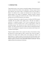
1
Joona Hänninen
Using Gocator laser profiling sensor with HALCON
machine vision software
Thesis
Spring 2015
Seinäjoki University of Applied Sciences
Automation Engineering
1(42)
SEINÄJOKI UNIVERSITY OF APPLIED SCIENCES
Thesis abstract
Faculty: School of Technology
Degree programme: Automation Engineering
Specialisation: Electricity Automation
Author: Joona Hänninen
Title of thesis: Using Gocator laser profiling sensor with HALCON machine vision
software
Supervisor: Petteri Mäkelä
Year: 2015
Number of pages: 42
Number of appendices: 1
Gocator 2300 series laser profile scanners are smartcams that use laser to scan an
object. Smartcam means that the device has a built-in software with a user interface.
The purpose of this thesis was to create a program with HALCON’s HDevelop
machine vision software that works with the Gocator 2340A laser profile scanner.
The program shows a 3D model of the scanned object and counts the holes in it.
The object used is a metal plate with 6 holes. After that the program code from
HDevelop is exported to a C# file. This file is then used in Microsoft Visual Studio
and then it is possible to create a standalone version of the program so that
HALCON HDevelop is not needed to run the program.
The theory part of this thesis explains what machine vision is and the history of it. It
also introduces the features and specifications of Gocator 2300 series profiling
sensors, HALCON HDevelop and Microsoft Visual Studio.
Keywords: machine vision, profile scanner, halcon, hdevelop, gocator, visual
studio
2(42)
SEINÄJOEN AMMATTIKORKEAKOULU
Opinnäytetyön tiivistelmä
Koulutusyksikkö: Tekniikan yksikkö
Tutkinto-ohjelma: Automaatiotekniikka
Suuntautumisvaihtoehto: Sähköautomaatio
Tekijä: Joona Hänninen
Työn nimi: Gocator profiiliskannerin käyttö HALCON-konenäköohjelmiston kanssa
Ohjaaja: Petteri Mäkelä
Vuosi: 2015
Sivumäärä: 42
Liitteiden lukumäärä: 1
Gocator 2300 sarjan profiiliskannerit ovat älykameroita, jotka käyttävät laseria
objektin skannaamiseen. Älykamera tarkoittaa sitä, että kamerassa on
sisäänrakennettu ohjelmisto, joka sisältää käyttöliittymän.
Tämän
opinnäytetyön
tarkoituksena
oli
tehdä
HALCON
HDevelop
konenäköohjelmiston avulla ohjelma, joka toimii Gocator 2340A profiiliskannerin
kanssa. Ohjelma tekee objektista 3D-mallin ja laskee objektissa olevien reikien
lukumäärän. Tässä työssä käytetty objekti on metallilevy, jossa on kuusi reikää.
Tämän jälkeen ohjelmakoodi muutetaan HDevelopista C# -muotoon. Tätä
ohjelmakoodia käytetään Microsoftin Visual Studiossa, jonka avulla voidaan tehdä
standalone-ohjelma, jota pystyy käyttämään ilman HALCONin HDevelopohjelmistoa.
Teoriaosuus kertoo konenäöstä ja sen historiasta. Lisäksi selvitetään Gocator 2300sarjan profiiliskannerien, HALCON HDevelop- ja Microsoftin Visual Studioohjelmistojen tärkeimmät ominaisuudet ja piirteet.
Avainsanat: konenäkö, profiiliskanneri, halcon, hdevelop, gocator, visual studio
3(42)
TABLE OF CONTENTS
Thesis abstract .................................................................................... 1
Opinnäytetyön tiivistelmä..................................................................... 2
TABLE OF CONTENTS ...................................................................... 3
Figures and Tables.............................................................................. 5
Abbreviations ...................................................................................... 7
1 INTRODUCTION ............................................................................ 8
2 MACHINE VISION IN GENERAL .................................................... 9
2.1 History of machine vision .......................................................................... 10
2.2 Machine vision today ................................................................................ 10
2.3 Camera types............................................................................................ 11
3 GOCATOR 2300 LASER PROFILING SENSOR .......................... 12
3.1 Gocator 2300 series specifications ........................................................... 13
3.2 Systems overview ..................................................................................... 16
3.3 User interface overview ............................................................................ 18
4 HALCON MACHINE VISION SOFTWARE.................................... 20
4.1 Features and availability ........................................................................... 20
4.2 HDevelop User Interface ........................................................................... 21
5 VISUAL STUDIO ........................................................................... 22
5.1 Features and availability ........................................................................... 22
5.2 User Interface ........................................................................................... 23
6 PROJECT ..................................................................................... 24
6.1 Equipment and hardware .......................................................................... 24
6.2 Connection ................................................................................................ 25
6.3 Scanning ................................................................................................... 26
6.4 The program ............................................................................................. 27
6.4.1 Program execution .......................................................................... 28
6.4.2 Converting the program to Visual Studio ........................................ 34
7 SUMMARY AND RESULTS .......................................................... 39
BIBLIOGRAPHY................................................................................ 40
4(42)
APPENDICES ................................................................................... 42
5(42)
Figures and Tables
Figure 1. A simplified camera setup (Sick AG 2006) ............................................... 9
Figure 2. Lid color verification on food packages (Sick AG 2006) ......................... 10
Figure 3. Example of a camera output and analyzing (Sick AG 2006) .................. 11
Figure 4. LMI Technologies logo (LMI Technologies 2015b) ................................ 12
Figure 5. Gocator 2300 series profile sensor (LMI Technologies 2015a) .............. 12
Figure 6. Gocator 2300 series dimensions (LMI Technologies 2014b) ................. 13
Figure 7. Standalone system setup (LMI Technologies 2014a, 17) ...................... 16
Figure 8. Dual-sensor system (LMI Technologies 2014a, 18) ............................... 17
Figure 9. Multi-sensor system (LMI Technologies 2014a, 19) .............................. 17
Figure 10. Gocator Web Interface (LMI Technologies 2014a, 42) ........................ 18
Figure 11. HALCON logo (MVTec Software GmbH 2015a) .................................. 20
Figure 12. HDevelop interface (MVTec Software GmbH 2009, 9) ........................ 21
Figure 13. Visual Studio logo (Microsoft 2015a) ................................................... 22
Figure 14. Screenshot of a Windows Forms Application in Visual Studio 2013 .... 23
Figure 15. Overview of the setup .......................................................................... 24
Figure 16. Screenshot of the Network and Sharing Center on Windows .............. 25
Figure 17. Gocator 2340 built-in software login screen ......................................... 26
Figure 18. The object moving through the scanning area ..................................... 27
Figure 19. The output of the scanning process in the Gocator software ............... 27
Figure 20. Code for getting the image from the profile scanner ............................ 28
6(42)
Figure 21. Message displayed when the program is ran ....................................... 28
Figure 22. Acquired image window in the HDevelop program .............................. 29
Figure 23. Code for generating the 3D model ....................................................... 29
Figure 24. 3D model window in the HDevelop program ........................................ 30
Figure 25. Code for extracting features and counting the holes ............................ 31
Figure 26. The result image after the hole counting in the HDevelop program ..... 32
Figure 27. The Variable View in the HDevelop program ....................................... 32
Figure 28. Hole counting in different position in the HDevelop program ............... 33
Figure 29. Hole counting for multiple objects in the HDevelop program ............... 33
Figure 30. Export window in HDevelop ................................................................. 34
Figure 31. HDevelop Template in Visual Studio.................................................... 35
Figure 32. Add existing item in Visual Studio ........................................................ 36
Figure 33. Add As Link .......................................................................................... 37
Figure 34. Finished program in Visual Studio ....................................................... 37
Table 1. Gocator 2300 series specifications 1 (LMI Technologies 2014b) ............ 14
Table 2. Gocator 2300 series specifications 2 (LMI Technologies 2014b) ............ 15
Table 3. Elements of Figure 10 explained (LMI Technologies 2014a, 42 & 43) .... 19
7(42)
Abbreviations
PLC
Programmable Logic Controller.
CCD
Charge-coupled device.
SDK
Software Development Kit.
IP Code
Ingress Protection Marking
8(42)
1 INTRODUCTION
Today machine vision is very common in automation industry. Almost every type of
industry can benefit from machine vision applications. There are various camera
types offered for many kinds of tasks. It is possible to take 2D and 3D images of
objects. The features such as edges are extracted from the image and then
analyzed based on the needs of the application. Seinäjoki University of Applied
Sciences offered a project that involved work with a Gocator 2300 series laser
profiling sensor and HALCON machine vision software.
The objective of this project is to explain the process of making a HALCON-program
compatible with the Gocator laser profiling sensor. After that the program is
converted to a standalone program. This is done by exporting the code from
HDevelop to a C# file and then the file is used in Visual Studio to create the
standalone program. This eliminates the need of HALCON HDevelop to run the
program. The results of this project can be used to make more advanced and better
machine vision applications compared to what can be achieved with Gocator builtin machine vision program.
Chapter 2 explains machine vision in general, the history of it and what is it today
and what kind of camera types are used in machine vision. After that chapter 3
introduces the Gocator laser profiling sensor and explains the features and
specifications of it. Chapter 4 gives an overview about the HALCON machine vision
software and gives ideas about the things and applications that can be done with it.
Chapter 5 gives an overview of the Visual Studio software by Microsoft. The last
chapter tells about the project part of this thesis.
9(42)
2 MACHINE VISION IN GENERAL
Machine vision is a field of automation that gathers information about the object and
environment with digital cameras and scanners which then transfer the information
to a computer or a PLC. It is one of the key technologies in manufacturing due to
the increasing demands on the traceability of products and the documentation of
quality. A typical machine vision application usually consists of cameras, lenses,
lighting, a PLC, a computer and robots and/or conveyor belts. A typical camera
system can be seen in Figure 1. (Steger, Ulrich & Wiedermann 2008, 1; Altroth
2010.)
Figure 1. A simplified camera setup (Sick AG 2006)
Machine vision is usually used to replace humans in jobs that require many
repetitive tasks. When a human can get tired over time and the chance for errors
gets bigger, machine vision does not have this problem. These kinds of jobs include
positioning, measurement, sorting and quality control. Machine vision is also useful
when high precision is required or when the environment is dangerous or not
accessible for a person. Above all, machine vision tends to do these jobs at a much
higher rate. An example of a machine vision application can be seen in Figure 2.
(Alroth 2010.)
10(42)
Figure 2. Lid color verification on food packages (Sick AG 2006)
2.1 History of machine vision
The first steps of machine visions were taken in the late 1940s and early 1950s, but
the concept did not become industrialized before the 1960s and 70s when
Massachusetts Institute of Technology developed an image analysis system that
controlled a robotic arm for industrial use. The invention of the CCD sensor in 1969
played a significant role in the success of machine vision. In the 1980s machine
vision expanded fast on the industrial level and at this point cameras and other
equipment for industrial applications became commercially available. In the 1990s
the improvement of computer technology made machine vision systems more
effective and practical, thus becoming even more common in factories. (Wilson
2014; Kirsch 2009.)
2.2 Machine vision today
Today machine vision applications can be found in almost any area of industry such
as automotive, electronics, food, pharmaceutics, logistics and wood industries. A
simple example of a machine vision application would be a bottle recycling machine.
In the recent years the so called smart cameras have been introduced to the market.
These cameras have a built-in image analysis unit that eliminates the need for a
11(42)
PC. They are cost efficient and compact solutions for some machine vision
applications. (Sick AG 2006; Alroth 2010.)
2.3 Camera types
Cameras that are used for machine vision applications are categorized into three
categories: vision sensors, smart cameras and PC-based systems and they are all
digital. Vision sensors are configured to perform a certain task and they produce
results by themselves. Smart cams also analyze the image and produce results by
themselves, but they are a lot more flexible than vision sensors. In PC-based
systems the camera captures the image that is then transferred to a PC where the
analysis tasks and the results are made. PC-based systems are usually used when
the amount of data is large. Figure 3 shows an output image of a camera with an
application that extracts certain features from the image. Features that are correct
are marked as green and features that do not match the wanted values/tolerances
are marked as red. (Sick AG 2006.)
Figure 3. Example of a camera output and analyzing (Sick AG 2006)
12(42)
3 GOCATOR 2300 LASER PROFILING SENSOR
The Gocator is a laser profiling sensor manufactured by LMI Technologies (See
Figure 4 for a logo). It is a smart sensor which means that it can be connected
straight to a computer or a PLC without the need of a third party software. The profile
sensor uses a laser to measure cross-sectional shapes of parts and material
surfaces (See Figure 5). To be able to generate a digital image of the scanned
object, it has to move through the scanning area. The cross-sections can be used
to create 3D point clouds that represent whole parts. The same sensor can also be
used to generate high detail laser intensity images that can be used with common
2D image processing software. (LMI Technologies 2015a.)
Figure 4. LMI Technologies logo (LMI Technologies 2015b)
Figure 5. Gocator 2300 series profile sensor (LMI Technologies 2015a)
13(42)
3.1 Gocator 2300 series specifications
The Gocator 2300 series features five standard models for different size scan areas
for different size objects. They can be customized to suit specific automation
requirements. Figure 6 shows the dimensions of all 2300 series scanners and
defines the meaning of CD, MR and FOV. The working scan area is marked with
red. (LMI Technologies 2014b.)
Figure 6. Gocator 2300 series dimensions (LMI Technologies 2014b)
14(42)
In Table 1 the dimensions, weight and specifications of each Gocator 2300 series
models are listed as well as the scan areas of the models. The definitions for some
of the specifications can be found in Figure 6.
Table 1. Gocator 2300 series specifications 1 (LMI Technologies 2014b)
GOCATOR
2300 SERIES
2320
2330
2340
2350
2370
2380
1280
1280
1280
1280
1280
1280
0.01
0.01
0.01
0.01
0.04
0.04
0.0018 - 0.003
0.006 - 0.014
0.013 - 0.037
0.019 - 0.060
0.055- 0.200
0.092- 0.488
0.014 - 0.021
0.044 - 0.075
0.095 - 0.170
0.150 - 0.300
0.275 - 0.550
0.375 - 1.100
40
90
190
300
400
350
25
80
210
400
500
800
18 - 26
47 – 85
96 – 194
158 – 365
308 – 687
390 - 1260
2M
2M
3R
3R
3B
3B
3R
3R, 3B
3B
3B
35x120x149.5
49x75x142
49x75x197
49x75x272
49x75x272
49x75x272
Mount type
Side
Top
Top
Top
Top
Top
Weight (kg)
0.8
0.74
0.94
1.3
1.3
1.3
MODELS
Data Points /
Profile
Linearity Z (+/% of MR)
Resolution
Z
(mm)
Resolution X
(mm)
Clearance
Distance (CD)
(mm)
Measurement
Range
(MR)
(mm)
Field of View
(FOV) (mm)
Recommende
d Laser Class
Other
Laser
Classes
Dimensions
(mm)
15(42)
In Table 2 the specifications and features that apply to all Gocator 2300 series
models are listed. These include things like the IP code and the material that the
housing is made of. It also shows the temperatures where the sensors work the
best.
Table 2. Gocator 2300 series specifications 2 (LMI Technologies 2014b)
ALL 2300 SERIES MODELS
Scan Rate
Approximately 170 Hz to 5000 Hz
Interface
Gigabit Ethernet
Inputs
Outputs
Differential Encoder, Laser Safety Enable,
Trigger
2x Digital output, RS-485 Serial (115 kBaud), 1x
Analog Output (4 - 20 mA)
Input Voltage (Power)
+24 to +48 VDC (13 Watts); RIPPLE +/- 10%
Housing
Gasketed aluminum enclosure, IP67
Operating Temperature
0 to 50 °C
Storage Temperature
-30 to 70 °C
Vibration Resistance
Shock Resistance
10 to 55 Hz, 1.5 mm double amplitude in X, Y
and Z directions, 2 hours per direction
15 g, half sine wave, 11 ms, positive and
negative for X, Y and Z directions
Browser-based GUI and open source SDK for
configuration and real-time 3D visualization.
Scanning Software
Open source SDK, native drivers, and industrial
protocols for integration with user applications,
third-party image processing applications, and
PLCs.
16(42)
3.2 Systems overview
The Gocator sensors can be used and installed in many scenarios. They can be
connected as standalone, dual-sensor or multi-sensor systems. In standalone
systems, usually only a single Gocator sensor is required and it can be connected
to a computer’s Ethernet port for setup. It can also be connected to encoders,
photocells or PLCs. See Figure 7 for more details. (LMI Technologies 2014a, 17.)
Figure 7. Standalone system setup (LMI Technologies 2014a, 17)
Dual-sensor systems use two Gocator sensors that work together to output a
combined result. The controlling sensor is the Main sensor and the other sensor is
the Buddy sensor. Three installation orientations are possible for the Gocator’s
software: Opposite, Wide and Reverse. A Gocator Master is required in order to
connect two sensors to a dual-sensor system and the sensors are connected to it
with Gocator Power and Ethernet to Master cordsets. See Figure 8 for more details.
(LMI Technologies 2014a, 17.)
17(42)
Figure 8. Dual-sensor system (LMI Technologies 2014a, 18)
Multi-sensor systems use two or more sensors that are connected to a Gocator
Master networking hardware that provides a single point of connection for power,
safety, encoder and digital inputs. The Master is used to ensure that the scan timing
is precisely synchronized across the sensors. The communication of the sensors
and client computers are done via an Ethernet switch. Master networking hardware
does not support digital, serial or analog output. See Figure 9 for more details. (LMI
Technologies 2014a, 18.)
Figure 9. Multi-sensor system (LMI Technologies 2014a, 19)
18(42)
3.3 User interface overview
The Gocator 3D smartcam has a built-in user interface. It can be accessed via
Ethernet by typing the given IP-address to a web browser. The connection has to
be established to the Main sensor. In the Gocator web interface the sensor can be
configured. The numbers of Figure 10 are explained in Table 3 on the next page.
(LMI Technologies 2014a, 42.)
Figure 10. Gocator Web Interface (LMI Technologies 2014a, 42)
19(42)
Table 3. Elements of Figure 10 explained (LMI Technologies 2014a, 42 & 43)
Element
Description
Contains settings for sensor system layout, network, motion and
1
Manage page
2
Scan page
3
Measure page
4
Output page
5
Dashboard page
6
CPU
Load
alignment, handling jobs and sensor maintenance.
Contains settings for scan mode, trigger source, detailed sensor
configuration and performing alignment.
Contains built-in measurement tools and their settings.
Contains
settings
for
configuring
output
protocols
used
to
communicate measurements to external devices.
and
Speed
Provides monitoring of measurement statistics and sensor health.
Provides important sensor performance metrics.
7
Help
8
Toolbar
9
Configuration area
Provides controls to configure scan and measurement tool settings.
10
Data viewer
Displays sensor data, tool setup controls and measurements.
11
Log
Displays messages from the sensor.
Provides links to online help resources, firmware updates and SDK.
Controls sensor operation, manages jobs and replays recorded
measurement data.
20(42)
4 HALCON MACHINE VISION SOFTWARE
HALCON is a machine vision software developed by MVTec Software GmbH (See
Figure 11 for logo) launched in 1997 and first distributors in Japan and Germany. It
is suitable for low and high level image processing and it is used in many types of
industries such as wafer and die inspection, medical, automotive, surveillance and
remote sensing. HALCON supports multiple programming languages and operating
systems and is able to analyze 1D, 2D and 3D images. The programming
environment used by HALCON is called HDevelop. (MVTec Software GmbH 2015a;
MVTec Software GmbH 2015b.)
Figure 11. HALCON logo (MVTec Software GmbH 2015a)
4.1 Features and availability
HALCON uses a library of more than 2000 operators and provides tools for various
industry applications including surface inspections for defect recognition, bar code
and data code reading, print inspection and positioning and alignment of objects,
holes and such. HALCON has ready-to-use interfaces to many industrial cameras
and frame grabbers. Additional image acquisition devices can also be integrated
into HALCON. It supports programming languages like C, C++, C#, Visual Basic
and Delphi. HDevelop programming environment has over 900 examples that can
be examined for a better understanding of a specific operator. HALCON is available
for Windows, Linux and OS X. (MVTec Software GmbH 2015a; MVTec Software
GmbH 2009.)
21(42)
4.2 HDevelop User Interface
As seen in Figure 12 the typical HDevelop User Interface consists of a main window
that has four different windows called Graphics Window, Program Editor, Variable
View and Operator Window. Graphics Window shows the current picture, Program
Editor shows the current program code, Variable View lists the images and variables
of the application and Operator Window shows the parameters of the selected
operator. (MVTec Software GmbH 2009, 9.)
Figure 12. HDevelop interface (MVTec Software GmbH 2009, 9)
The user interface is customizable for the user’s needs. All windows can be closed,
resized and repositioned. (MVTec Software GmbH 2009, 9.)
22(42)
5 VISUAL STUDIO
Visual Studio is a programming environment created by Microsoft (See Figure 13
for logo) and is used as a development environment for Windows and .NET
platforms. It can be used to create Windows applications, Windows services,
console applications, Windows Mobile Applications and more. (James Avery 2005.)
Figure 13. Visual Studio logo (Microsoft 2015a)
The programming language can be chosen by the user. It launched in 1997 and it
combined all the previous programming environments, Visual C++, Visual Basic and
others, into one application. (James Avery 2005.)
5.1 Features and availability
Microsoft Visual Studio offers tools to make applications for many different
platforms, including Windows, Android and iOS devices. The programming
languages are C++, Python, HTML5, JavaScript, C#, Visual Basic and F#. Visual
Studios contains features that make application development faster and easier,
such as IntelliSense, which is a trademark feature for Visual Studio. IntelliSense
helps programming by showing the available classes and the methods available on
those classes. Microsoft Visual Studio supports only Windows operating systems.
(Microsoft 2015b; James Avery 2005.)
23(42)
5.2 User Interface
As seen in Figure 14 the User Interface consists of different windows displayed
inside of Visual Studio. These windows can be moved and resized to fit the user’s
needs. Figure 14 shows what a new empty Windows Forms Application looks like.
(James Avery 2005.)
Figure 14. Screenshot of a Windows Forms Application in Visual Studio 2013
The area on the left is the document window that is used to open and work with files.
The current file is a Windows form. The window on the top right is the Solution
Explorer. This window keeps track of all the files and projects in the solution. The
bottom right window is the Properties Window. This window shows the properties
and settings for the object selected, in this case the Form1.cs file. The toolbox can
be found on the far left. It holds all the elements such as buttons and text fields that
can be dragged and dropped to the windows form. (James Avery 2005.)
24(42)
6 PROJECT
The project part of this thesis consists mainly of making the program with HALCON’s
HDevelop software and converting it to a standalone program with Microsoft’s Visual
Studio 2013. The setup used was made by Seinäjoki University of Applied Sciences.
6.1 Equipment and hardware
The equipment and hardware used in this project consists of a computer, a Gocator
2340A smart profile sensor and a conveyor belt. The conveyor belt motor was
controlled by a frequency converter and had an adjustable speed knob on the
control box. The motor had a pulse sensor that could send speed information to the
Gocator camera so the speed of the object was known in the scanning process. This
way the output image is not stretched even if the speed changes. Figure 15 shows
an overview of the setup.
Figure 15. Overview of the setup
25(42)
6.2 Connection
The connection between the Gocator profile scanner is established by an Ethernet
cable. The computer’s network settings must be configured by putting the correct
IP-address in the settings in order to get the connection working. In this case the
network used by the Gocator profile scanner is stated as “Unidentified network” as
shown in Figure 16.
Figure 16. Screenshot of the Network and Sharing Center on Windows
After the connection has been established the profile scanner built-in software can
be accessed with a web browser by typing the IP-address into the web address field.
If the connection is working, a login screen comes visible and asks for the user name
and password as shown in Figure 17. After that the built-in program is useable.
26(42)
Figure 17. Gocator 2340 built-in software login screen
The configuration of the scanner is done in the built-in software. The software has
a lot of auto-set features so most of the settings can be automatically defined for the
best values and results.
6.3 Scanning
After the right parameters have been set in the Gocator software, the scanning can
be started by pressing the “Play” button in the user interface. When the laser is on
the object has to be moved on the conveyor belt through the scanning area that can
be seen in Figure 18.
27(42)
Figure 18. The object moving through the scanning area
When the scanning is complete, the results can be seen in the Gocator software as
shown in Figure 19. By opening the “View” list it is possible to choose what image
is wanted to be viewed such as the intensity image or the 3D model.
Figure 19. The output of the scanning process in the Gocator software
6.4 The program
Since one of the strengths of HDevelop is the wide collection of examples, the
program made here uses some of those examples with changed parameters to fit
the needs of this program. LMI Technologies also provides an example program for
their Gocator cameras that comes with the best parameters for the image acquisition
28(42)
code. A Visual Studio solution example provided by HALCON is used in the
conversion to a standalone program part. Some of the most essential lines of code
are presented, not all. For the whole HDevelop program code see Appendix 1. The
scan settings that define the resolution and other image quality factors are defined
in the Gocator built-in software.
6.4.1
Program execution
When the program is ran the first step is the initializing of the profile scanner with
the correct parameters with the lines of code seen in Figure 20. The parameters
define how we connect to the scanner and what kind of information we want from it.
Figure 20. Code for getting the image from the profile scanner
After that a window opens (See Figure 21) that tells the user to move the object
through the scanning area. At this point the program waits until the scanning is
complete.
Figure 21. Message displayed when the program is ran
After the scanning is complete the program receives the raw and intensity images
from the scanner. Then the values are converted to real world values so that the
images are not stretched and the object in the image looks like the real one. After
that a window is opened (See Figure 22) that shows the intensity image that was
29(42)
acquired. The program tells the user that “Run” needs to be pressed in order for the
program to continue execution.
Figure 22. Acquired image window in the HDevelop program
When “Run” is pressed the program generates a 3D model of the object with the
code seen in Figure 23. These lines of codes include various tasks such as the
default pose of the model and the tutorial messages how to manipulate the 3D
model.
Figure 23. Code for generating the 3D model
30(42)
Then a window (See Figure 24) is opened where you can inspect the generated
model. The program tells the user that “Continue” button in the window has to be
pressed in order to continue the execution to the hole counting process.
Figure 24. 3D model window in the HDevelop program
After “continue” is pressed, the program extracts certain features and edges of the
object and with a series of operators it defines which features are circles and what
are not. These lines of code can be seen in Figure 25.
31(42)
Figure 25. Code for extracting features and counting the holes
The parameters for this code were found by Trial and error method. The parameters
were changed until the program could count the right number of circles in
consecutive scans with the position of the metal object changed after every scan.
Then the circles are counted as holes and the program shows the result image (See
Figure 26) with the number of holes that are each shown as circles of different color
in the image.
32(42)
Figure 26. The result image after the hole counting in the HDevelop program
The Variable View window shows all the variables used in the program so far. It also
shows all the images and features extracted from the object. See Figure 27 for
details.
Figure 27. The Variable View in the HDevelop program
33(42)
At this point the user can start the process from the start again by pressing “Run”.
The program still works even if the object is in a different position (See Figure 28)
or if there are multiple objects (See Figure 29).
Figure 28. Hole counting in different position in the HDevelop program
Figure 29. Hole counting for multiple objects in the HDevelop program
34(42)
However, the program might not work with objects of different kind, since it uses
specific parameters for the operators that are targeted for this certain metal piece.
In order to use it for different size of holes the parameters have to be changed.
6.4.2
Converting the program to Visual Studio
Due to some unsolved problems with converting the program shown in the earlier
chapter, a different program called circles.hdev (Found in the HALCON example
folder) will be used in this conversion. The program extracts circular shapes of an
image and shows them as different colors. This method should also work with other
programs.
First the program has to be exported to a C# file from HALCON’s HDevelop. This
can be done by choosing “File” and then “Export…” from the list. After that a window
(See Figure 30) pops up where the settings of the export can be configured.
Figure 30. Export window in HDevelop
35(42)
In this example the settings seen in Figure 30 are used. The “Use Export Template”
must be checked in order to make the program work with the ready-to-use template
provided by HALCON.
Now the Visual Studio template has to be opened. The default path for the files is
“C:\Users\Public\Documents\MVTec\HALCON11.0\examples\c#\HDevelopTemplate”
The template form consists of a black window and a “Run” button as seen in Figure
30. This template uses the HDevelop libraries and tools so there is no need to add
those manually. The “Run” button does the same thing as it does in the HDevelop
program. The black box seen in Figure 31 is a tool provide by HALCON that
functions as the image window that shows the image that would be shown in
HDevelop.
Figure 31. HDevelop Template in Visual Studio
36(42)
Now the circles.cs file that was exported from HDevelop has to be brought to Visual
Studio. This can be done by right clicking “HDevelop Template” in the Solution
Explorer window (Selected in Figure 31) and then pressing “Add” and “Existing
item…” as seen in Figure 32.
Figure 32. Add existing item in Visual Studio
After that the file browser pops up and the circles.cs file has to be found. When the
file is selected, it is important not to press “Add”, but to press the little arrow facing
down next to the button and selecting “Add As Link” as seen in Figure 33.
37(42)
Figure 33. Add As Link
Now the program is ready to be ran. This can be done by pressing the “Start” button
located in the toolbar on top. Now the program is running and the program window
appears. When “Run” is pressed the program runs the code generated in HDevelop
by using the HDevelop libraries converted to C#. When the program is finished a
message saying “Finished.” can be seen on the bottom and the result image
appears in the black window as seen in Figure 34.
Figure 34. Finished program in Visual Studio
38(42)
This program can now be ran via an .exe. This eliminates the need of the actual
HDevelop software since all the needed libraries are included in the project made in
Visual Studio.
39(42)
7 SUMMARY AND RESULTS
The goal of the thesis was to make a program in HALCON’s HDevelop that used
the Gocator 2340A profile scanner and after that convert it to a standalone program
with Microsoft’s Visual Studio that works without the HALCON machine vision
software. This thesis also functions as a guide in how to do all of these things. The
code used in HDevelop is provided in the appendices section.
The use of Gocator’s built-in software was fairly easy due to the simple user
interface and many types of automatic setups for scan settings. The built-in software
is only needed to switch on the scanner and setting the image resolution and quality
wanted.
The making of the HDevelop program was a success and it did every task that was
planned, which in this case is the 3D model of the object and the counting of holes.
HALCON’s HDevelop is a complicated software that is capable of doing almost any
task that has something to do with machine vision. Because of that lots of
experimenting with the program was required due to the lack of knowledge in coding
with it. The possibility of being able to change the speed of the conveyor belt was
also discussed, but not implemented to the final program.
The conversion to a standalone program did not succeed as well. A number of
different ways were tried for making the standalone program and the one used in
chapter 6.4.2 was the fastest and the easiest. The converted program had some
problems connecting to the Gocator profile scanner and the cause of this could not
be solved within the time limit of this project. It might have dozens of reasons, for an
example the fact that the example template provided by HALCON was created using
older versions of the Visual Studio and the .NET Framework. In the end a different
HDevelop program that did not use the camera was used and it worked well. It would
have been possible to code the standalone program by hand without using the
ready-to-use template, but it would have taken too much time.
The results of this project can be used to develop the programs further and to find
the cause of the errors in the converted standalone program. It may be necessary
to contact MVTec Software of LMI Technologies to get help for solving this problem.
40(42)
BIBLIOGRAPHY
Ahlroth 2010. Konenäköjärjestelmät. [pdf-document]. [Ref. 04.02.2015]
Available: https://noppa.aalto.fi/noppa/kurssi/as-116.1100/luennot/AS116_1100_luentokalvot__konenako.pdf
James Avery. 2005. What Is Visual Studio. [www-page]. O’Reilly Media, Inc. [Ref.
24.02.2015].
Available:
http://archive.oreilly.com/pub/a/windows/2005/08/22/whatisVisualStudio.html?p
age=1
Kirsch 2009. A Vision of the Future: The Role of Machine Vision Technology in
Packaging and Quality Assurance. [pdf-document]. [Ref. 04.02.2015].
Available: http://www.iopp.org/files/public/MSUKathleenKirsch.pdf
LMI Technologies. 2014a. Gocator 2300 & 2880 Series. User manual. [pdfdocument]. LMI Technologies. [Ref. 23.02.2015].
Available: http://lmi3d.com/manuals/gocator/gocator-4.1/pdf/151594.1.4.12_MANUAL_User_Gocator-2300-2880-Series.pdf
LMI Technologies. 2015a. [www-page]. LMI Technologies. [Ref.11.02.2015].
Available: http://www.lmi3d.com/products/gocator/profile-sensor/
LMI Technologies. 2015b. [www-page]. LMI Technologies. [Ref.11.02.2015].
Available: http://www.lmi3d.com/products/gocator/
LMI Technologies. 2014b. Gocator 2300 Series. [pdf-document]. LMI
Technologies. [Ref. 18.02.2015].
Available:
http://downloads.lmi3d.com/system/files/Gocator/documents/Gocator%202300
%20Series/DATASHEET_Gocator_2300.pdf
Microsoft. 2015a. [www-page]. Microsoft. [Ref. 26.02.2015].
Available: http://www.visualstudio.com/
Microsoft. 2015b. [www-page]. Microsoft. [Ref. 26.02.2015]. Available:
http://www.visualstudio.com/fi-fi/products/visual-studio-community-vs
MVTec Software GmbH. 2015. [www-page]. MVTec Software GmbH. [Ref.
24.02.2015].
Available: http://www.halcon.com/halcon/
41(42)
MVTec Software GmbH. 2009. HALCON the Power of Machine Vision. [pdfdocument]. MVTec Software GmbH. [Ref. 24.02.2015].
Available:
http://www.sensorsincorporated.com/uploaded/Doc/Halcon%209.0%20Brochur
e.pdf
MVTec Software GmbH. 2015b. Facts. [www-page]. MVTec Software GmbH. [Ref.
27.02.2015].
Available: http://www.mvtec.com/de/unternehmen/10years/facts-about-mvtechistory/
Sick AG 2006, Machine vision Introduction v2.2, [pdf-document]. [Ref. 21.3.2014].
Available: http://www.sick.com/uk/enuk/home/products/product_portfolio/Documents/Machine%20Vision%20Introdu
ction2_2_web.pdf
Steger, C., Ulrich, M. & Wiedemann, W. 2008. Machine Vision Algorithms and
Applications. 2008. Wiley-VCH Verlag GmbH & Co. KGaA.
Wilson 2014. Keystones of machine vision system design.[www-page]. [Ref.
04.02.2015]
Available: http://www.vision-systems.com/articles/print/volume-18/issue8/features/keystones-of-machine-vision-systems-design.html
42(42)
APPENDICES
APPENDIX 1. The code for HALCON’s HDevelop program shown in chapter 6.4
1(4)
2(4)
3(4)
4(4)