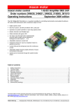
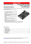
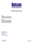
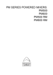
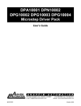
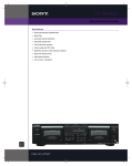
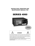
1
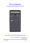
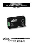
MDC010 - 050101
50V, 10A Brushless Controller
User’s Guide
A N A H E I M
A U T O M A T I O N
910 East Orangefair Lane, Anaheim, CA 92801
e-mail: [email protected]
L010678
(714) 992-6990 fax: (714) 992-0471
website: www.anaheimautomation.com
June 2013
MDC010-050101 Speed Controller Features
• 1 Quadrant Digital Speed Control
• 6-50 VDC Voltage Range
• Max Speed at 80,000rpm
• Maximum current of 10A (5A rated)
• Digital Signal presets Direction of Rotation
• Protection Against Thermal Overload
• Small Design
• Motor Blockage Protection
• Status Indication
• Easy Connectivity/Integration into Motherboard
General Description
The MDC010-050101 has a very compact design with a high efficiency speed controller that offers a
operating voltage of 50VDC, while maintaining an output current of 5A. The amplifier also offers a large
number of inputs and outputs such as the speed monitor, current limiting, speed ranges, direction of rotation presetting, enable, operating status, etc. While offering all these features the MDC010-050101 offers
many protective features against overcurrent, undervoltage and overvoltage, short ciruit and thermal overload to ensure the controller runs correctly. Anaheim Automation also offers an MDC010-EVALBOARD
for intial start-up.
Pin Assignment
L010678
June 2013
Specifications
Electrical Data
Nominal Supply Voltage (V) - 6-50VDC
Absolute Minimum Supply Voltage (V) - 6VDC
Absolute Maximum Supply voltage (V) - 55VDC
Max. Output Voltage - 0.95V
Continous Output Current (I) - 5A
Max. Output Current (I) - 10A
Switching Frequency - 46.8kHz
Max. Speed (motor with 1 pole pair) - 80,000rpm
Inputs
Set value Speed - Analogue input (0-5V); Resolution: 1024 Steps
Enable - +2.4-+55V (R=100kohms) or switch against V
Direction - +2.4-+28V(R=100kohms) or switch against V
Speed Range <<DignIN1>> - +2.4-+55V(R=47kohms at 5V) or switch against Gnd
Speed Range <<DignIN2>> - +2.4-+55V(R=47kohms at 5V) or switch against Gnd
Set Current Limit - External Resistor (1/16 W) against Gnd
Hall Sensors - <<Hall Sensor 1>>,<<Hall Sensor>>, <<Hall Sensor 3>>
Output
Motor Speed <<Monitor n>> - Digital Output Signal, 5V(R=47kohms)
Status Indication <<Ready>> - Digital Output Signal, 5V(R=47kohms)
Voltage Output
+5 VDC Output Voltage <<V Hall>> - +5 VDC, man. 35 mA
Motor Connections
Motor Connections - <<Motor Winding 1 (Phase A) >>, <<Motor Winding 2 (Phase B) >>,
<<Motor Winding 3 (Phase C) >>
Ambient Temperature
Operation - -10-+450C
Storage - -40-+850C
Humidity Range
Non condensating - 20-80%
Protective Functions
Current Limitation (cycle-by-cycle) - Adjustable up to Maximum 10A
Blockage - Motor Current limitation if motor shaft is blocked for longer than 1.5s
Undervoltage shutdown - Shutdown if V<6VDC
Overvoltage Shutdown - Shutdown if V>56VDC
Thermal Overload Protection of Power Stage - Shutdown if T>1000C
Mechanical Data
Weight - approx. 9g
Dimensions - 43.18 x 27.94 x 12.7mm (1.7 x 1.1 x 0.5in)
Terminals
Pin header 1 - 2 x 9 pins (Double-Row, pitch 2.54mm (0.1in)
Pin header 2 - 8 pins (Single Row, pitch 2.54mm (0.1in)
L010678
June 2013
Inputs
Speed Range and Mode selection with <<DigIN1>> and <DigIN2>>
The digital inputs <<DigIN1>> [20] and <<DigIN2>> [21] determine both, the operation mode (digital speed
controller or digital sepeed actuator) and the speed range in speed set value mode.
DigIN1
DigIN2
1 Pole Pair
4 Pole Pair
8 Pole Pair
0
0
1
0
500-5,000 rpm
125-1,250 rpm
62-625 rpm
0
1
500-20,000 rpm
125-5,000 rpm
62-2,500 rpm
1
1
500-80,000 rpm
125-20,000 rpm
62-10,000 rpm
Open Loop Speed Control, 0-95% PWM Depending on the
<<Set value speed>> Input Voltage
Please Note
If the signal level of the digital inputs DigIN1 [20] and DigIN2 [21] are changed, the new levels are adopted
by a disable-enable procedure.
If the input <<Dig>> is not connected (floating) or a voltage higher than 2.4V is applied, the input is inactive.
Input not connected (floating) Input voltage> 2.4V
Logic 1
Input Active
If the input <<DigIN>> is set to ground potentialor a voltage smaller than 0.8V is applied, the digital input is inactive
Input set to Gnd Input Voltage<0.8V
Input Inactive
The inputs <<Digin1>> and <<DigIN2>> are protected against overvoltage.
Logic 0
Digital input 1
Pin Number [20] <<DigIN1>>
Digital input 2
Pin number [21] <<DigIN2>>
Input Voltage Range
0-+5V
Input Impedance
47kohms pull-up resistor against 5V
Continuous Overvoltage Protection
-55-+55V
Set Value <<Set Value Speed>>
The external analogue set value is predetermined at the <<Set value speed>> input [26]. The <<Set value
speed>> input sets the rotational speed of the motor shaft.
By adjusting the signal levels on digital inputs <<DigIN1 [20]>> and <<DigIN2 [21]>> the speed range
must be set in advance.
L010678
June 2013
DigIN1
DigIN2
1 Pole Pair
4 Pole Pair
8 Pole Pair
0
0
Open Loop Speed Control, 0-95% PWM Depending on
the <<Set value speed>> Input Voltage
1
0
500-5,000 rpm
125-1,250 rpm
62-625 rpm
0
1
500-20,000 rpm
125-5,000 rpm
62-2,500 rpm
1
1
500-80,000 rpm
125-20,000 pm
62-10,000 rpm
Note
If the level of the digital inputs DigIN1 [20] and DigIN2 [21] are changed, the new levels are adopted by
a disable-enable procedure.
Set Value Voltage
0-0.1V
0.1-5.0V
Description
Operation at minimum speed
Linear speed adjustment
The actual speed value is calculated according the following formula:
Known Values
Minimum speed (see table above) nmin [rpm]
Maximum speed (see table above) nmax [rpm]
Set value voltage Vset [V] respectively speed n [rpm]
Sought Value
Sought Value
Speed n [rpm]
Set value voltage [V]
Solution
Solution
The <<Set value Speed>> input is protected against overvoltage.
Set Value Speed Input
Input Voltage
Resolution
Input Impedance
Continuous Overvoltage Protection
L010678
Pin number [26] <<Set Value
Speed>>
0-+5V (reference to Gnd)
1024 steps (4.88mV)
107kohms (in range 0-+5V)
-55-+55V
June 2013
<<Enable>>
The <<Enable>> input enables or disables the power stage.
If a voltage higher than 2.4V is applied to the <<Enable>> input, the amplifier is activated (Enable). A speed ramp will be performed during acceleration.
Input Voltage>2.4V
Enable
Motor Shaft Running
If the input is not connected (floating) or ground potential is applied to the
<<Enable>> input, the power stage is high impedant and the motor shaft
freewheels and slows down (Disable).
Input not connected (floating)
Input set to Gnd
Input Voltage<0.8V
Power Stage Switched Off
The <<Enable>> input is protected against overvoltage.
Disable
Enable
Pin Number [22] <<Enable>>
Input Voltage Range
0-+5V
Input Impedence
100kohms (in range 0-+5V)
Continuous Overvoltage Protection
-55-+55V
Delay time
Max. 40ms
<<Direction>>
The <<Direction>> input determines the rotational direction of the motor shaft. When the level changes,
the motor shaft slow down with a ramp to standstill, and accelerates with a speed ramp in the opposite
direction, until the target speed is reached again.
If the input is not connected (floating) or ground potential is applied to the <<Direction>> input, the
motor shaft runs clockwise (CW).
CW
Input not connected (floating)
Input set to Gnd
Input voltage<0.8V
Clockwise (Wise)
If a voltage higher than 2.4V is applied to the <<Direction>> input, the motor shaft runs
counter-clockwise (CCW).
Input Voltage>2.4V
Counter-Clockwise (CCW)
The <<Direction>> Input is protected against overvoltage.
CCW
L010678
Direction
Pin Number [23] <<Direction>>
Input Voltage Range
0-+5V
Input Impedence
100kohms (in range 0-+5V)
Continuous Overvoltage Protection
-55-+55V
Delay Time
Max. 40ms
June 2013
<<Set Current Limit>>
The <<Set Current Limit>> input is used for setting the continuous output current limitation in the range
of 0.5-10A.
The current set at the input <<Set Current Limit>> sill stay available for an indefinite period of time.
Note
The limiting calue should be below the rated motor current (max.continuous current).
Set Value Current
Pin Number [25] <<Set Current Limit>>
Referenced to Ground
Pin Number [24] <<Gnd>>
Current Limit
Value
To parameterize the preferred current
limiting value, an external resistor (at least
62.5 mW) between current limiting input
<<Set Current Limit>> Pin [25] and ground
<<Gnd>> Pin [24] must be added.
Resistance Value
(E24 Series)
10A
Input Floating
9A
220 kohms
8A
91 kohms
7A
56 kohms
6A
36 kohms
5A
24 kohms
4A
16kohms
3A
10.0 kohms
2A
5.6 kohms
1A
2.7 kohms
0.5A
1.2 kohms
<<Hall Sensor 1>>, <<Hall Sensor 2>>, <<Hall Sensor 3>>
The <<Set Current Limit>> input is used for setting the continuous output current limitation in the range
of 0.5-10A.
Hall Sensor 1
Pin number [13] <<Hall Sensor 1>>
Hall Sensor 2
Pin number [15] <<Hall Sensor 2>.
Hall Sensor 3
Pin number [17] <<Hall Sensor 3>>
Input Voltage Range
Input Impedance
L010678
0-+5V
22 kohms pull-up resistors to 5V
Voltage Level <<Low>>
Max. 0.8V
Voltage Level
<<High>>
Min. 2.4V
Continuous Voltage
-30-+30V
Suitable for Hall Sensors IC’s with SchmittTrigger behavior and
open collector or pushpull outputs.
June 2013
Outputs
+5 VDC Output Voltage <<Vcc Hall>>
An internal auxiliary voltage of +5VDC is provided for:
- Hall Sensor supply coltage <<Vcc Hall>>
- For external set value potentiometer (recommended value: 10kohms)
- Gating the signals: <<Enable>> and <<Direction>>
The output is protected against continuous short circuit.
+5 VDC Output Voltage
Pin Number [25] <<Set Current Limit>>
Referenced to Ground
Pin Number [24] <<Gnd>>
Output Voltage
Max. Output Current
+5VDC 5%
35mA
Motor Speed Monitor <<Monitor n>>
The <<Monitor n>> output gives information on the actual speed of the motor shaft. The actual speed is
available as a digital frequency signal (high/low). The output<<Monitor n>> is protected against continuous short circuit.
Motor Speed Monitor
Pin number [18] <<Monitor n >>
Output Voltage Range
0-+5V
Output Impedance
47kohms
Known Values
- Number of poles pairs of motors zpol
- Frequency at <<Monitor n>> output [Hz] respectively Speed n [rpm]
Sought Value
Sought Value
Frequency at <<Monitor n>> [Hz]
Speed n [rpm]
Solution
L010678
Solution
June 2013
Status Indication <<Ready>>
The <<Ready>> output can be used to report the state of operational readiness or a fault condition to a
master control unit.
In normal cases (no fault) the output is switched to 5V.
Ready (no fault)
5V
In case of a fault the output is switched to Ground.
Fault (not ready)
0V (Gnd)
Possible reasons for a fault message:
Undervoltage
Fault message occurs in case supply voltage +V<6VDC. To reset the fault condition the
amplifier must be disabled and the supply voltage +V must be higher than 6VDC.
Overvoltage
Fault message occurs in case supply voltage +V>56VDC. To reset the fault condition the
amplifier must be disabled and the power stage temperature must fall below 80deg Celcius.
Thermal
Overload
Fault message occurs in case power stage temperature is>100deg Celcius. To reset the
fault condition the amplifier must be disable and the power stage temperature must fall below 80deg Celcius.
Invalid Hall
Sensor
SIgnals
The amplifier recognizes invalid conditions at the Hall Sensor inputs. To reset the fault condition the amplifier must be disable and the Hall Sensors must be wired correctly.
The output <<Ready>> is protected against continuous short circuit.
Status
Indication
Output Voltage
Range
Output
Resistance
L010678
Pin number [19] <<Ready>>
0-+5V
47kohms
June 2013
Protective Features
Undervoltage Protection
The power stage will be disabled in case the supply voltage +Vcc drops below 6VDC. To reset the fault
condition the amplifier must be disabled and the supply voltage +Vcc must be higher than 6VDC.
Overvoltage Protection
The power stage will be disabled in case the supply voltage +Vcc rises above 56VDC. To reset the fault
condition the amplifier must be disabled and the supply voltage +Vcc must be lower than 54VDC.
Thermal Overload Protection
The power stage will be disabled in case the power stage temperature exceeds 1000C. To reset the fault
condition the amplifier must be disabled and the power stage temperature must fall to 800C.
Invalid Hall Sensor Signals
The power stage will be disabled in case invalid conditions at the hall sensor inputs occur. To reset the
fault condition the amplifier must be disabled and the hall sensors must be wired correctly.
Blockage Protection
If the motor shaft is blocked for longer than 1.5s, the current limit is set to the predetermined value at the
<<Set Current Limit>> input.
Definition <<Motor shaft blocked>>: A speed lower than 4154rpm (motor with 1 pole pair) occurs for longer
than 1.5s.
Note:
- No fault message occurs at the <<Ready>> output if blockage protection is active.
Current Limitation
The motor current will be limited to 0.5-10A depending on the value applied to the input <<Set Current
Limit>> by means of a cycle-to-cycle limitation.
Note:
- No fault message occurs at the <<Ready>> output if current limitation is active.
L010678
June 2013
Typical Hookup Drawing
Dimensions
L010678
June 2013
Torque Speed Curves
COPYRIGHT
Copyright 2006 by Anaheim Automation. All rights reserved. No part of this publication may be reproduced,
transmitted, transcribed, stored in a retrieval system, or translated into any language, in any form or by
any means, electronic, mechanical, magnetic, optical, chemical, manual, or otherwise, without the prior
written permission of Anaheim Automation, 910 E. Orangefair Lane, Anaheim, CA 92801.
DISCLAIMER
Though every effort has been made to supply complete and accurate information in this manual, the
contents are subject to change without notice or obligation to inform the buyer. In no event will Anaheim
Automation be liable for direct, indirect, special, incidental, or consequential damages arising out
of the use or inability to use the product or documentation.
Anaheim Automation’s general policy does not recommend the use of its’ products in life support applications
wherein a failure or malfunction of the product may directly threaten life or injury. Per Anaheim Automation’s
Terms and Conditions, the user of Anaheim Automation products in life support applications assumes all
risks of such use and indemnifies Anaheim Automation against all damages.
LIMITED WARRANTY
All Anaheim Automation products are warranted against defects in workmanship, materials and construction,
when used under Normal Operating Conditions and when used in accordance with specifications. This
warranty shall be in effect for a period of twelve months from the date of purchase or eighteen months
from the date of manufacture, whichever comes first. Warranty provisions may be voided if products
are subjected to physical modifications, damage, abuse, or misuse.
Anaheim Automation will repair or replace at its’ option, any product which has been found to be defective
and is within the warranty period, provided that the item is shipped freight prepaid, with previous authorization
(RMA#) to Anaheim Automation’s plant in Anaheim, California.
TECHNICAL SUPPORT
If you should require technical support or if you have problems using any of the equipment covered by this
manual, please read the manual completely to see if it will answer the questions you have. If you need
assistance beyond what this manual can provide, contact your Local Distributor where you purchased the
unit, or contact the factory direct.
ANAHEIM AUTOMATION
L010678
June 2013