1
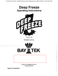
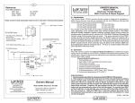
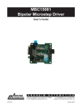
BLWS23MDA Series
24V, 15A Brushless Controller / Motor
User’s Guide
A N A H E I M
A U T O M A T I O N
910 East Orangefair Lane, Anaheim, CA 92801
e-mail: [email protected]
L010525
(714) 992-6990 fax: (714) 992-0471
website: www.anaheimautomation.com
January 2012
BLWS23MDA Driver Features
• Constant Velocity Mode
• 0.5V to 5V External Voltage Speed Control
• 2-Quadrant Operation
• Hall Sensor Feedback
• Short Circuit Protection
• Maximum Current Limit at 15.0 Amps
• Speed Out
• Direction Input
• TTL-CMOS Compatible Inputs
• Compact Size
• Screw type Terminal Block
General Description
The BLWS23MDA Series is a compact construction that implements a DC Brushless controller and a DC
Brushless motor in one streamline package. With the two parts combined into one casing, the need to wire
up the motor has been eliminated. The DC Brushless controller operates off 24VDC. The high-speed DC
Brushless motor can operate at 4000RPM, can generate up to 60 oz-in of continuous torque, and deliver
as much as 180W, with the BLWS23MDA5 offering. Using hall sensor feedback, the DC Brushless controller operates in a constant velocity mode. The driver is protected against over current (cycle-by-cycle), hall
sensor error and under voltage. An external potentiometer (10K) or external voltage (0.5-5VDC) can be
used to control the speed. The direction of the motor can be preset by the direction control input. A Stop
function can be done by grounding the Vspeed input.
Fault Protection
A cycle-by-cycle over current protection is provided when the motor peak current level exceeding the
current limit of 15A is produced. When the over current protection is activated, the controller shuts off
the outputs to the motor. For the shorter stack models of the BLWS23MDA series, care must be taken
not exceed the rated motor power.
Closed Loop (Constant Velocity Mode)
The driver is set for Closed Loop operation. Closed Loop operation is used for applications where speed
regulation is needed. Under closed loop operation, the speed is regulated despite changes to the load
and the power supply voltage.
Suggested Power Supplies
Part #
PSA24V2.7A
L010525
Description
DC Power Supply 24VDC at 2.7 Amps
January 2012
Specifications
Run Stop and Direction Inputs: (TB1, Pins 3 and 6)
TTL-CMOS Compatible
Logic “0” = 0-0.8VD
Logic “1” = OPEN
The Run Stop and Direction Inputs are pulled up through a 10k ohm resistor.
V Speed: (TB1, Pin 5)
To control the speed of the motor with an external DC voltage, a voltage from 0.5VDC (min) - 5VDC (max)
must be applied with reference to PGND (TB1, Pin 2).
0VDC - Motor will stop.
PG Output: (TB1, Pin 4)
An open drain pulse out put has a max rating of 30VDC/50mA.
RPM = 30 * PG OUT (in Hz)
+5V Output: (TB1, Pin 7)
The 5V output should only be used when using an external potentiometer to control the motor speed.
Drawing excessive current may damage the DC Brushless motor controller.
Output Current Rating:
15.0 amperes per phase maximum operating current
Power Requirements: (TB1, Pins 8 and 9)
18VDC (min) - 35VDC (max)
Operating Temperature:
Heat Sink: 0°-70° C
Motor Stop
The motor stop feature allows the stopping of a motor by shorting out the bottom drives of the three phases.
Grounding the Vspeed input does not allow motor operation and if operating causes rapid deceleration.
Motor Direction
The motor direction feature allows the changing of the rotation of the motor. This input should not be
changed while motion is in progress. A high (open) input causes the motor to turn in the CW direction,
while a low at this input causes the motor to turn in the CCW direction.
Speed Output
The PG OUT terminal (TB1 - pin 4) is used to determine the speed of the motor shaft.
RPM=30 x PG out (in Hz)
L010525
January 2012
Speed Adjust Setting
There are two ways to set the speed on this DC Brushless Motor Controller combination.
1. One is to use an external voltage or an external potentiometer. If a voltage is used to control the speed
of the motor, the 0.5V to 5V voltage can be tied on VSPD (TB1 - pin 5) with respect to PGND (TB1 - pin 2).
2. If an external potentimeter is used to control the speed of the motor, connect the pot wiper to VSPD
(TB1 - pin 5), the positive end of the potentiometer to +5V out (TB1 - pin 7) and the negative end to
PGND (TB1 - pin 2).
A ramp up profile at start up on VSPD (TB1 - pin 5) would alleviate excessive current draw from the power
supply. When the motor is rapidly accelerated from standstill, current drawn from the power supply can
measure up to ten times the rated motor current. This startup current spike can shutdown power supplies
by tripping the power supply’s current limit.
A ramp down profile from max operating speeds would alleviate any back emf generated. When the motor
is rapidly decelerated or stopped from high speed, the motor phase advances and this “returned energy”
voltage appears on the drive’s power supply pins. Returned energy voltages seen at the input pins in
excess of 35V will damage the driver.
The maximum ramp times are determined per application. Both the ramp up and ramp down speed profiles would need to be done with an external controller.
The maximum voltage that can be placed on VSPD is 10V. A voltage exceeding 10V will cause damage to
the driver. If a voltage other than 0.5V to 5V is needed to control the speed of ther motor, contact Anaheim
Automation for custom tuning of the VSPD input.
Note: Avoid changing the direction of rotation when the motor is already running in any
one direction.
The following instructions must be followed to prevent permanent drive failure due to over-current conditions that exist in dynamic direction reversals of the motor:
1. Stop the motor by grounding the RUN/STOP input
2. Wait for at least 500mS
3. Change the direction with the DIRECTION input
4. Run the motor by removing ground signal on the RUN/STOP input
L010525
January 2012
Heating Considerations
The temperature of the motor should never be allowed to rise above 70 degrees Celsius. If necessary,
mount the unit to an additional heat sink or air should be blown across the heat sink to maintain suitable
temperatures.
Terminal Block Descriptions
Pin #
Typical Hookup Drawing
Description
1
VIN
2
PGND
3
Run / Stop
4
PG OUT
5
Vspeed
6
Direction
7
+5Vout
TB1: Power In, Control
Inputs and Output
Dimensions and Ratings
Model
L (in.)
Torque (oz-in)
Power (W)
Current (A)
BLWS23MDA1
2.97
7.79
23.06
0.96
BLWS23MDA2
3.37
15.58
46.12
1.92
BLWS23MDA3
4.15
31.15
92.21
3.84
BLWS23MDA4
4.92
45.31
134.13
5.59
BLWS23MDA5
5.77
62.30
184.43
7.68
L010525
January 2012
COPYRIGHT
Copyright 2007 by Anaheim Automation. All rights reserved. No part of this publication may be reproduced,
transmitted, transcribed, stored in a retrieval system, or translated into any language, in any form or by
any means, electronic, mechanical, magnetic, optical, chemical, manual, or otherwise, without the prior
written permission of Anaheim Automation, 910 E. Orangefair Lane, Anaheim, CA 92801.
DISCLAIMER
Though every effort has been made to supply complete and accurate information in this manual, the
contents are subject to change without notice or obligation to inform the buyer. In no event will Anaheim
Automation be liable for direct, indirect, special, incidental, or consequential damages arising out
of the use or inability to use the product or documentation.
Anaheim Automation’s general policy does not recommend the use of its’ products in life support applications
wherein a failure or malfunction of the product may directly threaten life or injury. Per Anaheim Automation’s
Terms and Conditions, the user of Anaheim Automation products in life support applications assumes all
risks of such use and indemnifies Anaheim Automation against all damages.
LIMITED WARRANTY
All Anaheim Automation products are warranted against defects in workmanship, materials and construction,
when used under Normal Operating Conditions and when used in accordance with specifications. This
warranty shall be in effect for a period of twelve months from the date of purchase or eighteen months
from the date of manufacture, whichever comes first. Warranty provisions may be voided if products
are subjected to physical modifications, damage, abuse, or misuse.
Anaheim Automation will repair or replace at its’ option, any product which has been found to be defective
and is within the warranty period, provided that the item is shipped freight prepaid, with previous authorization
(RMA#) to Anaheim Automation’s plant in Anaheim, California.
TECHNICAL SUPPORT
If you should require technical support or if you have problems using any of the equipment covered by this
manual, please read the manual completely to see if it will answer the questions you have. If you need
assistance beyond what this manual can provide, contact your Local Distributor where you purchased the
unit, or contact the factory direct.
ANAHEIM AUTOMATION
L010525
January 2012