1
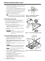
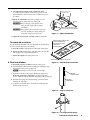
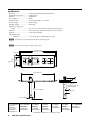
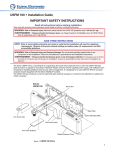
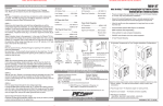
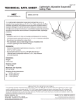
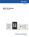
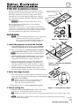
PCM 340 Installation Notes
1-gang and 2-gang Accessory Mounting
Points (e.g., Power Sockets)
The Extron PCM 340 Drop Ceiling Projector Mount is used for
hanging PoleVault™ System AV products and various projectors.
The PCM is installed above the drop ceiling and secures the
adjustable pipe in a pass-through pipe adapter plate. The pipe
then supports the mounting of the Extron PMK 550 and UPB 25
projector bracket.
C Maximum load for the PCM is 50 lbs (22.7 kg).
Base
Plate
Pipe
Adapter
Pipe Adapter Plate
Wing Nuts (4)
T-frame
Securing
Screws (4)
Pipe Adapter
Set Screws (2)
The key components of the PCM 340 are shown in figure 1.
Also included in the kit are:
4 turnbuckles, 5 lag eye bolts, 5 concrete anchors, 2 cable clamps,
1 safety wire – 15 ft., 2 tie wire – 30 ft., 4 T-frame screws, 2 set screws,
1 location screw, 4 adhesive pads, 11 hole plugs, 1 escutcheon ring,
(1) 25 inch slotted projector pipe with 1 snap-in trim piece.
Installation
NRefer to local building standards and codes to verify that the
installation will meet the regulatory requirements.
Observe all local and national building and safety codes,
UL requirements, and ADA Accessibility Guidelines.
1.Install the projector to verify the location.
a. At the predetermined location for the projector, identify the
ceiling tile and T-frame where the PCM will be installed.
b. Remove the ceiling tile, and mark the projector's maximum
and minimum throw distances on the T-frame (see figure 2).
PRELIMINARY
Figure 1 — PCM 340 parts
X"
Projector
Front
Y"
T-frame
N Refer to the projector manufacturer's manual for details.
c. Place the PCM base plate over the T-frame, between the two
marks. Lightly tighten the T-frame securing screws (which
can be inserted on the inside or outside of the PCM).
d. Back out the Pipe Adapter set screws on the adapter plate.
Slide the slotted pipe into the adapter, aligning the holes
in the pipe with those in the adapter (see figure 3). Tighten
the pipe location screw and the set screws to secure the pipe.
Minimum and
Maximum
Throw Distance Marks
Figure 2 — Minimum and maximum
throw distances
e. Install the UPB 25 projector bracket and the projector onto
the end of the pipe. Refer to the UPB 25 User Manual for details.
2.Verify the image location.
a. Turn on the projector, loosen the wing nuts and slide the base plate
and projector left and right, viewing the image to verify the proper
location for a centered image.
T Remember to use the vertical and horizontal offsets when
aligning the projector. Adjust pipe height if needed.
Refer to the projector manual for details.
b. When image location is verified, lock down the wing nuts.
3.Cut the ceiling tile.
Align Pipe holes with
location screw holes.
Insert location screw
and secure.
Figure 3 — Insert pipe into adapter
a. Mark the location of the PCM base plate on the T-frame, before
removing it, to aid in replacing it in the correct location.
T Mark the screen direction on the back of the tile to help with orientation of the tile when replacing it after cutting.
N With assistance, carefully remove the UPB 25 with the projector still attached from the slotted pipe.
Remove the slotted pipe.
68-1573-01
Rev B
05 09
PCM 340 Installation Notes
1
PCM 340 Installation Note, cont'd
b. Measure the distances X and Y (see figure 2) from the inner
vertical section of the front and left T-frame runners to the
center of the Pipe Adapter Plate.
c. Using these dimensions, mark and cut a hole (using a 2 inch
hole saw) for the projector pipe in the ceiling tile (see figure 4).
d. If required, to prepare the ceiling tile for a power outlet, use
the PCM plate and trace and cut out the 2-gang hole in the
ceiling tile for a UL approved Raco junction box.
Top Side
Underside
If this is not required, proceed to step 5.
T Install any optional power outlets in the 2-gang opening on
the mounting plate, towards the outside edge of the mount,
so they do not interfere with the PMK 550 when installed.
Figure 4 — Mark and start cutting on
underside. Finish on top side.
4.Install the electrical box.
Raco 231
The following method is recommended for integrating a 4S
Raco electrical box (not supplied) on the PCM base plate
(e.g., a Raco 231, 2 1/8" deep, 4"x4" electrical box and a Raco 778,
1/2" raised, 4"x4" plaster ring or similar).
PRELIMINARY
Install the Raco box on the PCM plate as follows:
a. Attach the box to the plate, using the smallest notches in
opposite corners of the cut-out (see figure 5). Do not
tighten the screws fully at this time.
b. On the room side of the tile, slide the plaster ring under
the screws.
Use the smallest
notches when
attaching the
Raco box.
c. Fully tighten the screws
W For safety, complete all wiring of the electrical
boxes and accessories after the plate is fully
installed and secure.
Raco 778
Figure 5 — Install Raco box and plaster ring
5.Secure the PCM base plate to the ceiling.
a. Replace the cut ceiling tile, checking the orientation and
aligning the hole(s) with the PCM's adapter plate.
b. Replace the PCM base plate over the ceiling tile
c. Push the slotted pipe up through the hole into the adapter
plate and tighten the location and set screws to secure the
pipe in place.
Drill holes and
attach tie wires
10° out from
vertical.
Attach safety cable
to center holes and
secure with cable
clamps.
o
10
d. Attach the four turnbuckles to the mounting plate, one at
each corner.
C DO NOT rest or lean on the mounting plate or
suspended ceiling when attaching the turnbuckles
and tie wire, or when drilling into the ceiling.
N For safest installation, insert the turnbuckle from the
outside so that it hooks inwards.
Attach tie wire
to the turnbuckles
and eye bolts.
e. Mark and drill holes in the structural ceiling at 10 degrees Figure 6 — Attach tie wire and safety cable
out from vertical. Drill a fifth hole centered above the PCM
for the safety cable (see figure 6).
f. Install appropriate anchors or lag eye bolts for the
structural ceiling into each drilled hole.
g. Loop the safety cable through the anchor or lag eye bolt,
attach it to the plate center holes (see figure 6) and secure it
with the cable clamps.
2
PCM 340 Installation Notes
h. Cut appropriate lengths of the supplied tie wire.
Loop the wire through the anchors or lag eye bolts and
the turnbuckles, then twist the wire around itself at least
five times.
Secure PCM to frame
(from either side)
PCM
i. Tighten the turnbuckles by hand (see figure 7), and
level the plate so that it just rests on the grid.
T-frame
C The four hanging wires should be taut,
taking the full weight of the completed
installation.
C Overtightening the turnbuckles could cause
the T‑bar assembly to be lifted, making the
suspended ceiling bowed and unsafe.
Adjust the turnbuckles to take
up any slack in the hanging wire.
Figure 7 — Adjust turnbuckles
j. Tighten the four T-frame securing screws on the PCM.
Attach washer and nut and
insert threaded rods
through holes on the
ends of the
mounting plate.
Threaded rod installation
For this method, threaded rods (not supplied) are used instead
of wire to secure the plate to the ceiling:
PRELIMINARY
a. Insert the rods through the holes at the ends of the plate.
b. Secure the rods with washers and nuts. The rods take the
full weight of the completed installation.
c. Adjust the length to keep the plate level.
Attach washer and nut and secure.
6.Final installation.
a. Install the projector assembly and lock it into place.
Figure 8 — Threaded rod installation
b. Tuck the signal cables into the slotted pipe and firmly snap
the trim piece into place (see figure 9).
N The trim piece can be cut to the desired length.
c. Open the escutcheon ring and, with the tabs uppermost,
fit the ring around the slotted pipe (see figure 10), then
close it. Slide the ring up until it is snug against the ceiling tile.
d. Insert the hole plugs into the remaining open holes in the
visible part of the pipe.
Slotted
Projector Pipe
Snap-in
Trim Piece
e. Complete any further device installation according to the
manufacturer's manuals.
Figure 9 — Snap in trim piece
Figure 10 — Fit ring and hole plugs
PCM 340 Installation Notes
3
Specifications
Mounting���������������������������������������� Ceiling mountable with included hardware
Maximum load capacity��������������� 50 lbs (22.7 kg)
Material������������������������������������������� Aluminium
Color/finishes�������������������������������� White
Pipe dimensions���������������������������� 25" (635 mm) length, 1.5"-11.5 NPT
Product weight������������������������������ 4.5 lbs (2.0 kg)
Shipping weight���������������������������� 9 lbs (5 kg)
Regulatory Compliances
Safety���������������������������������������� CE, c-UL, UL, for use with UL Listed mount and projector
Vibration����������������������������������������� ISTA 1A in carton (International Safe Transit Association)
Warranty����������������������������������������� 3 years parts and labor
Adjustment ranges
PCM 340����������������������������� 1.5" to 23" drop, 21.5" adjustability, 0.5" steps
N Drop distances are measured from the bottom of the hanger plate.
N Specifications are subject to change without notice.
26.39" (670.3 mm)
24.72" (627.8 mm)
1.00" (25.4)
8.00"
(203.2 mm)
6.00"
(152.4)
23.71" (602.3 mm)
2.42"
(61.4)
1.15"
(29.2 mm)
Threaded Holes Appear
On This Side Only
Drop
1.5" min. to 23.00" max.
2.00" (50.8 mm)
(1 1/2"-11.5 NPT)
Extron USA - West
Headquarters
+800.633.9876
Inside USA / Canada Only
+1.714.491.1500
+1.714.491.1517 FAX
4
Extron USA - East
Extron Europe
Extron Asia
Extron Japan
Extron China
Extron Middle East
+800.633.9876
+800.3987.6673
+800.7339.8766
+81.3.3511.7655
+81.3.3511.7656 FAX
+400.883.1568
+971.4.2991800
+971.4.2991880 FAX
+1.919.863.1794
+1.919.863.1797 FAX
+31.33.453.4040
+31.33.453.4050 FAX
+65.6383.4400
+65.6383.4664 FAX
Inside USA / Canada Only
PCM 340 Installation Notes
Inside Europe Only
Inside Asia Only
© © 2009 Extron Electronics.
All rights reserved.
Inside China Only
+86.21.3760.1568
+86.21.3760.1566 FAX