1
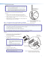
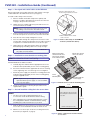
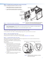
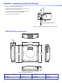
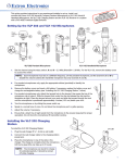
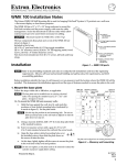
PVM 220 • Installation Guide
The Extron PVM 220 is an enclosure for the safe mounting of PoleVault®
system devices in the plenum area of a suspended ceiling.
The main enclosure will fit on a 24 x 24 inch framed tile space and is
used to mount a PoleVault System switcher and the power supply,
and other optional Extron AV devices. The PVM 220 comes with a
detachable device mounting plate that makes installation of PoleVault
devices and accessories easier.
E
VE
L
PEAK
ITY
SITIV
L
NORM
LE
DIO
LIFT
AU
VOICE
L
PEAK AL
NORM
3
1
5
X
AU
FIG
SE
LE
CT
2
4
IN
PU
TS
AU
DI
O
INPU
T
SIGNA
SIGNA AL
AD
SEN
JU
ST
PAGI
SENS NG
OR
PO PV
LEV S
AU 40
LT 5S
SW A
ITC IP
HE
R
Device
Mounting Plate
CON
Suitable for use in environmental air space in accordance with
Section 300-22(C) of the National Electrical Code, and Sections
2-128, 12-010(3) and 12-100 of the Canadian Electrical Code, Part 1,
CSA C22.1. The product has been additionally investigated to
UL 2043, "Fire Test for Heat and Visible Smoke Release for Discrete
Products and Their Accessories Installed in Air-Handling Spaces ".
PVM 220
Enclosure
R
The PVM 220 is UL Listed for use in plenum airspaces: meets UL
2043 for heat and smoke release.
Access
Door
Figure 1. PVM 220 Installed (Access Door Open)
NOTES:
• The following products are approved for use in the UL 2043 rated Extron PVM 220 enclosure as part of the Extron
PlenumVault System: • PVS 305SA IP PoleVault Switcher • PVS 405D PoleVault Switcher • CC 100C Network Codec
• IPL 250 IP Link Controller • SW2 HDMI Switcher
In addition, any Extron product that has been individually tested and UL 2043 approved can also be used.
Contact Extron for a complete list of plenum rated products.
• The PoleVault switcher and other AV devices are not supplied with the PVM 220.
• For full installation, configuration, menus, connector wiring, and operation details of the PoleVault switcher, see the
relevant PoleVault System Installation Guide, available at www.extron.com.
Pre-installation
Read all instructions before installing this enclosure.
IMPORTANT INSTRUCTIONS:
• Installation of this product must be done by a qualified, professional installer.
• Installation of this product (including the wiring of devices) must meet national electrical codes, and local building
standards and codes.
• A readily accessible disconnect device shall be incorporated in the building installation wiring.
• Building installation wiring to be protected by a UL Listed circuit breaker rated 15 A or less.
• Observe all local and national building and safety codes, UL requirements, and ADA Accessibility Guidelines.
Identify the location where the PVM 220 will be installed. Typically this would be a T-grid suspended ceiling with minimum 24 x
24 inch tiles, close to the display device location. Take into consideration access to a power source and the proximity of other
utilities (gas, water, fire sprinklers and so forth). Also consider the other devices that are associated with the PoleVault switcher,
such as speakers, input and output devices, wallplates and control devices, and the facility communication systems (such as a
department information system).
PVM 220 Features
The PVM 220 is comprised of a main enclosure, an access door, and a device mounting plate (see figure 1).
The device mounting plate fits onto the door frame and allows access to the devices and cables when the door is open.
Additional installation hardware is needed for this installation, and it should be supplied by the installer.
Included hardware for installation:
For Enclosure Installation
Size and (Quantity)
For Device Mounting
(Quantity)
Suspension cables
15 feet x Á inch dia. (4)
#4-40 device mounting screws
(10)
Cable locks
(4)
Zip ties
long (4), short (15)
Lag eye bolts
1¼ x ¼ inch (4)
Signal cable tie downs
(15)
Cable clamps
1 inch (1), ¾ inch (2)
1
PVM 220 • Installation Guide (Continued)
Installation
a. Remove this screw on
the right and left sides
of the mounting plate.
Step 1 — Remove device mounting plate from the access door.
a.
Door Tether “T”
Open the access door and unscrew the two Phillips screws that are
located in the bottom corners of the plate (left and right sides), near the
door latches and door tether "T."
NOTE: Do not remove any of the screws located below
the hinges.
Bottom of Door
(inside right
corner view)
b. Swing the bottom of the plate up to separate it from the door frame,
then slide the plate to the right until it becomes free of the hinge pins
on the door frame.
b. Swing the mounting plate out from the door frame
and slide the plate to the right, off the hinge pins.
Retain the device mounting plate for later use (see step 6).
Figure 2. Remove the mounting plate from
the door.
Step 2 — Remove ceiling tile and install suspension cables.
For threaded rod installation see step 3, second section.
a.
At the location where the PVM 220 is to be installed, remove the ceiling
tile and mark the T-grid for that tile then remove the adjacent tiles to make
working on the grid easier.
b. At an approximate angle of 10 degrees out from each corner of where the
PVM 220 will be installed, mark and drill four holes in the structural
ceiling for the suspension cable anchors.
c.
Figure 3. Tie the cable to the ceiling anchor.
Screw a lag eye bolt (or an appropriate anchor) into each hole.
d. Thread the looped end of the suspension cable though the bolt eyehole,
Thread the cable down through the cable
lock, through the hole on the frame of the
enclosure and back up through the lock.
pass the rest of the cable through the loop and tighten.
Allow each cable to hang down.
Step 3 —Suspend the main PVM 220 enclosure from the ceiling.
a.
Lift and place the PVM 220 enclosure carefully onto the T-grid so
that it sits squarely on the grid.
Locking Pin
Cable Lock
b. Holding a cable lock, press the locking pin down (following arrow
directions) and pass the loose end of one the cables down through
the large hole in the lock.
Continue to push the cable down until about 12-15 inches of cable
has exited the lock.
c.
Pass the loose end of the cable directly through the corner hole on
the PVM 220 enclosure and then back up through the other large hole
in the lock.
Pass at least six inches of cable out through the top of the lock.
d. Repeat for each corner.
e.
Adjust the cable tension through all locks, making each cable taut
without lifting the PVM 220 off the T-grid.
Figure 4. Secure the PVM 220 to the ceiling
with cable on all corners.
2
Product Category
For threaded rod installation
NOTES:
• … inch or à inch diameter threaded rods are recommended to
be used for installing this product.
Insert threaded rods
through holes on the ends
of the mounting plate.
• The threaded rod should be properly secured to the ceiling
structure. For example, properly fasten a unistrut to the ceiling
structure and attach threaded rods using nuts and washers.
Secure the frame to the structural ceiling using threaded rods.
To do this:
a.
Attach four rods to the support structure by using, for example
a unistrut, one over each corner of the PVM 220 installation location.
b. Attach a rod to each corner securing point of the PVM 220 with nuts and
washers (see figure 5, at right).
c.
Adjust all the nuts to secure the PVM 220 to the ceiling, keeping it level
and without lifting the unit from the T-grid.
Attach washers and nuts and secure.
Figure 5. Secure the PVM 220 to the ceiling
with threaded rod.
Step 4 — Run AC power wiring to the AC module in the PVM 220.
If power is not available close to the installation location, install a junction box or power source at the area.
NOTES:
• This must be done by a qualified electrician and must meet local and national electrical, building and safety codes and
all the regulatory requirements. See the Important Instructions on page 1.
• Use metal conduit only to run wire to the AC module.
• Do not run power cable in the same conduit as signal cables.
• Use 14 AWG gauge solid copper wire only, as required by the installed power receptacles.
Run the power cable through metal conduit and wire it into the PVM 220 power module.
To do this:
a.
Unscrew the two center screws (left and right side) of
the power inlet/control panel and remove from
the enclosure (see figure 6).
a. Remove power
module from the
PVM 220 enclosure.
b. Unscrew the two screws on the corners and detach
the outer cover.
c.
Attach the metal conduit to the outer cover.
NOTES:
• Remove only the knockouts that are to be
used for cabling. Leave intact the unused
knockouts.
• The three knockout sizes are Œ inch to
– inch, – to 1 inch, and 1 to 1… inch.
d. Run the wires through the conduit and connect to the
AC receptacles.
e.
Reassemble the power module.
f.
Reattach the module to the enclosure.
NOTE: The power module outlets must be used to
power installed AV devices only.
1/2" Conduit
Knockout
b. Remove the cover
from power module.
c. Attach a metal conduit.
Figure 6. Remove the power module from the
enclosure to attach the metal conduit.
3
PVM 220 • Installation Guide (Continued)
Step 5 — Run signal and control cables to the PVM 220.
Run the signal and control cables either into cable clamps or through
conduit attached to the PVM 220 enclosure (see figure 7).
1. Push the cable clamp into the
knockout from inside the enclosure.
To install a cable clamp on the enclosure:
a.
Select a suitable sized cable clamp for the quantity and
thickness of cable to be fed into the enclosure. See the note
on page 3, Step 4 for knockout sizes.
b. Identify the most suitable cable entry point and remove one
or more knockouts as needed.
NOTE: Remove only the knockouts that are to be used
for cabling. Leave intact the unused knockouts.
c.
Remove the large nut from the back of the cable clamp and
insert the clamp into the enclosure knockout from the inside.
2. Attach the nut from the outside
of the enclosure.
d. Place the nut on the clamp and tighten to secure.
e.
f.
Pass the cables through the clamp into the enclosure. Leave
enough cable slack at the PVM 220 to ensure cable connection
to any device is maintained when the access door is open.
Figure 7. Install a cable clamp on the PVM 220
enclosure (viewed from above).
Tighten down the cable grip until the cables are held firmly.
Avoid damaging or bending cables at too sharp an angle.
NOTE: See the PoleVault System Installation Guide for
full cable connection details.
Step 6 — Install devices onto the device mounting plate.
NOTE: The maximum door load is 15 lbs (6.8 kg).
Mount the PoleVault
switcher with the front
panel facing outwards
in the marked location.
Mount other optional
devices as desired.
To mount the devices and accessories:
a.
Carefully align the switcher with the appropriate holes in the
marked location (indicated by arrows on the mounting plate).
R
CO
NFI
G
SE
LE
CT
INP
1
UT
S
2
b. Secure the switcher with the supplied #4-40 » inch mounting
3
4
AU
DI
5 O
X
AU
INPU
T
screws, tightening each one until snug. Do not overtighten.
Mount the power supply onto the device mounting plate in the
marked location (indicated by arrows on the mounting plate),
using the supplied screws.
NOTE: Replacement power supplies must be either the
equivalent Extron power supply, or a UL Listed NEC
Class 2 power supply.
PEAK
AL
AU
DIO
SIGN
AL
VOIC
ELIFT
LE
VE
L AD
JU
PEAK
ST
NORM
AL
SIGN
AL
PAG
SENING
SOR
SEN
SITI
PV
VITY
PO
LE
S
VA 40
UL 5S
T SW A
ITC IP
HE
R
E
c.
NORM
Device
Mounting Plate
PoleVault Switcher
Power Supply
Figure 8. Install the devices onto the mounting plate.
21.5"
(54.6 cm)
d. Mount any other devices following the procedures in the
supplied device guide.
Step 7 — Cut and install the ceiling tile in the access door.
NOTES:
• The door can accept a ceiling tile thicknesses of
Œ-1… inches. Check the tile thickness before cutting.
Cut the ceiling tile to 22 x 21.5 inches
and use that part for insertion into the
access door.
22.0"
(55.9 cm)
• If the ceiling tiles have a specific pattern direction, ensure
the overall pattern direction is maintained when cutting
and fitting the cut tile insert into the access door.
a.
Mark the dimensions (22 inches by 21.5 inches) for the PVM 220
access door on the installation tile and cut the tile to size.
b. With the access door open, insert the cut ceiling tile into the
door frame (see figure 10, on page 5).
Bottom of Door (Door Locks)
Example: 24 x 24 inch Ceiling Tile
Figure 9. Cut the ceiling tile for insertion into the
4
access door.
Product Category
Step 8 — Install the device mounting plate onto the access door.
To fit the mounting plate and devices on the access door:
a.
Align and slide the device mounting plate onto the
two hinge pins located at the top of the door frame.
PVM 220 Enclosure
b. Secure the plate into place with the two mounting
plate screws, located at the bottom of the door frame.
Device Mounting
Plate Hinges
Device Mounting
Plate Hinge Pins
Device Mounting
Plate (with devices
installed)
Y
ITIVIT
L
PEAK
NORM
LEV
DIO
LIFT
VOICE
AU
NORM
L
PEAK AL
SIGNA
T
INPU
DIO
5
X
AU
AU
S
INP
UT
3
4
1
2
T
SE
LEC
FIG
CON
R
PoleVault
Switcher
(front panel
facing down)
SIGNA AL
EL
SENS
AD
JUS
T
PAGIN
SENS
G
OR
PO
PV
LEV S
AUL 40
T 5S
SW A
ITC IP
HER
E
Door Frame
Device Mounting
Plate Screws
Ceiling Tile
Insert
Figure 10. Insert the ceiling tile and attach the device mounting
Step 9 — Connect the cables to the devices.
plate to the access door (as viewed from below).
NOTES:
• See the PoleVault System Installation Guide or the relevant PoleVault switcher user guide for connecting cables and
devices to the PVS device.
• For cable connections to optional devices see the relevant device guide or manual.
Connect the fan cable (already installed in the enclosure) to the switcher power supply.
Connect and dress the other cables as needed, providing enough slack to open and close the access door.
Step 10 — Verify and configure the setup.
Turn on the power to all the devices. Verify and configure the system.
See the PVS 405D User Guide, or PVS 305SA IP User Guide available at www.extron.com for full details.
Step 11 — Attach the door tether to the door.
The PVM 220 enclosure has a coiled door tether installed on the right side of the enclosure (when viewed from the front).
After the device mounting plate is installed, the tether
should be attached to the door to ensure safety when the
door is opened.
Push the tether loop completely over the T tab on the door.
To attach the tether to the door:
a.
With the door fully open, locate the door tether
attached within the enclosure. The coiled tether
has a looped end to be attached to the door.
b. In the lower corners of the door locate the cutout
with a "T" shaped metal tab (see figure 11).
c.
Stretch the tether and close up the door until the
loop on the tether can be carefully slid over the
"T" tab on the door. Ensure the loop is completely
over the "T".
d. Carefully lower the door to the full extent of the
tether to ensure it functions correctly.
Figure 11. Attach the Tether to the Door (as viewed
from inside enclosure).
5
PVM 220 • Installation Guide (Continued)
Step 12 — Secure the door latches.
Both door latches can be made secure so the door cannot
be opened accidentally or inadvertently.
To secure the latches close the door and tighten down the
small set screws onto the latch (see figure 12).
For full safety secure both latches.
To secure the latch from opening tighten
down the set screw onto the latch.
Figure 12. Secure the door latches (side of door view).
PVM 220 Enclosure Dimensions
6.34"
(16.10 cm)
23.75"
(60.33 cm)
24.09"
(61.20 cm)
23.75"
(60.33 cm)
6.34"
(16.10 cm)
Figure 13. Enclosure Dimensions
6
Extron Headquarters
+1.800.633.9876 (Inside USA/Canada Only)
Extron Asia
+65.6383.4400
Extron China
+86.21.3760.1568
Extron Korea
+82.2.3444.1571
Extron Europe
+31.33.453.4040
Extron Japan
+81.3.3511.7655
Extron Middle East
+971.4.299.1800
Extron India
+91.80.3055.3777
© 2013 Extron Electronics — All rights reserved. All trademarks mentioned are the property of their respective owners.
www.extron.com
68-2383-01
Rev. A
10 13