1
IR420-D4
Installation Bulletin / Reference Guide
TM
This document is intended as a reference guide for installing and using a BENDER IR420-D4 ground
fault detector. This document includes installation, setup, and usage instructions. For complete details, including installation, setup, settings, and troubleshooting, refer to the IR420-D4 user manual,
document number TBP101012. This document is intended as a supplement and not a replacement to
the complete user manual.
Only qualified maintenance personnel shall operate or service this equipment. These instructions
should not be viewed as sufficient for those who are not otherwise qualified to operate or service this
equipment. This document is intended to provide accurate information only. No responsibility is assumed by BENDER for any consequences arising from use of this document.
Installation
Front Panel Display
Mounting
IR420-D4 series devices may be DIN rail mounted, or screw mounted using the black clips located on the top and bottom of the device. Screw mounting requires an extra black clip (article
number B98060008, sold separately).
Wiring - General
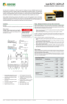
The IR420-D4 monitors a single-phase AC ungrounded
system. Refer to Figure 1 for wiring diagram. Use minimum AWG 24, maximum AWG 12 size wire. Refer to
IR420-D4 series user manual for complete technical details.
1
2
3
5
6
! DANGER
HAZARD OF ELECTRIC SHOCK,
EXPLOSION, OR ARC FLASH
4
• Disconnect all power before servicing.
• Observe all local, state, and national
codes, standards, and regulations.
1
7
6
3
1.
2
External supply voltage; 5A fuse
required for internal device protection (Use two fuses when powering device with ungrounded
power)
1.
LED “ON” (green): Illuminates when
power is applied to the device. Flashes
when the connection alarm is active.
2.
Equipment ground connections
2.
3.
Connections to monitored system
4.
Alarm relay K1: SPDT contact
LED “AL1” (yellow): Illuminates when
the prealarm is activated. Flashes when
the connection alarm is active.
5.
Alarm relay K2: SPDT contact
6.
Connection for optional external
test/reset input
4
Figure 2 - IR420-D4 front display
3.
LED “AL2” (yellow): Illuminates when
the main alarm is activated. Flashes
when CT connection alarm is active.
4.
LCD display
5.
TEST / UP button: Activates self-test /
scrolls up inside main menu.
6.
RESET / DOWN button: Resets device /
scrolls down inside main menu.
7.
MENU / ENTER button: Activates main
menu / Confirms (momuntary push) or
goes back a step (held > 1.5 s) inside
main menu.
Dimensions
Dimensions in inches (mm).
5
2.78”
(70.5)
1.87”
(47.5)
1.42” (36)
2.66” (67.5)
The factory default for relays K1 and K2 is normally deenergized operation.
1.77” (45)
Wiring - Contacts
Using a normally closed or normally open contact utilizes two factors: wiring out of the proper
terminal, and setting the respective contact to normally energized or deenergized operation.
Refer to the chart below for relay conditions. For changing the energized state of the contact,
refer to “Figure 6 - Contact operation” on the reverse side of this document.
3.54” (90)
1.22” (31.1)
Figure 1 - IR420-D4 wiring diagram
Device Relay Conditions
Relay Operation Setting
Device Alarm State
K1 STATE
K2 STATE
Normally deenergized mode (N/D)
Non-failsafe mode
“N/O” in device settings menu
Power ON, normal state (no alarms)
11-12 CLOSED
11-14 OPEN
21-22 CLOSED
21-24 OPEN
Energized in the alarm state
Power OFF
11-12 CLOSED
11-14 OPEN
21-22 CLOSED
21-24 OPEN
Relay will switch when the alarm is
activated.
Power ON, alarm state
11-12 OPEN
11-14 CLOSED
21-22 OPEN
21-24 CLOSED
Normally energized mode (N/E)
Failsafe mode
“N/C” in device settings menu
Power ON, normal state (no alarms)
11-12 OPEN
11-14 CLOSED
21-22 OPEN
21-24 CLOSED
Energized in the normal state
Power OFF
11-12 CLOSED
11-14 OPEN
21-22 CLOSED
21-24 OPEN
Relay will switch when the alarm is
activated, or when supply voltage
to the device is lost.
Power ON, alarm state
11-12 CLOSED
11-14 OPEN
21-22 CLOSED
21-24 OPEN
Bender Inc. • 800.356.4266 / 610.383.9200 • [email protected] • www.bender.org
Menu Flow Chart for Common Settings
Figure 4 through figure on the reverse side of this document contain flow charts for modifying
commonly used features and settings in the IR420-D4’s main menu. Not all available features
are listed in this document. For more information, consult the IR420-D4 user manual.
Menu Legend
DOWN ARROW button
< 1.5 s
Momuntary button push
UP ARROW button
> 1.5 s
Hold button for at least 1.5 s,
then release
R
T
MENU / ENTER button
Document NAE1018090 • 05.2012 • © Bender Inc. • Page 1/1 • Side 1/2
IR420-D4
Installation Bulletin / Reference Guide
TM
Figure 4 - Setting alarm trip values
Figure 6 - Contact operation
The IR420-D4 monitors for ground faults by measuring the system’s insulation resistance.
Alarm values are set in kΩ. R2 is the main alarm. A prealarm value (R1) may also be set to give
advanced notification.
Use this option to change the behavior of the contacts between normally deenergized (nonfailsafe) mode and normally energized (failsafe) mode. The two SPDT contacts may be changed
individually. Note that the IR420-D4 labels normally deenergized operation as “N/O” and normally energized operation as “N/C”; utilzing a normally open or normally closed contact only
depends on which contact output is wired.
1)
5)
1)
> 1.5 sec
6)
T
< 1.5 sec
> 1.5 sec
2)
6)
R
R
3)
7)
2)
< 1.5 sec
Prealarm value
Skip steps 4
through 6 if
this will not
change,
otherwise:
Main alarm value
Follow steps 4
through 6 to
adjust setpoint
if desired
8)
9)
4)
R
5)
10)
8)
T
> 1.5 sec
Press Once
> 1.5 sec
4)
> 1.5 sec
< 1.5 sec
x 2 To quit
< 1.5 sec
< 1.5 sec
Press Once
3)
7)
R
Failsafe
ON/OFF Select
R
< 1.5 sec
Setpoint Adjustment
= Flashing Symbol
= Flashing Symbol
Figure 5 - Latching behavior (fault memory)
Changing this setting to “ON” will cause the IR420-D4 to latch in the event of an alarm, and require a manual reset if the alarm clears. Changing this setting to “OFF” will cause the IR420-D4
to automatically reset if the alarm clears.
Technical Data
Refer to IR420-D4 series user manual (document TBP101012) or IR420-D4 series datasheet
(document NAE1012090) for detailed technical information.
1)
> 1.5 sec
6)
2)
< 1.5 sec
R
Press Once
7)
3)
> 1.5 sec
< 1.5 sec
8)
4)
> 1.5 sec
< 1.5 sec
5)
9)
T
R
= Flashing Symbol
Fault Memory
ON/OFF Select
Bender Inc. • 800.356.4266 / 610.383.9200 • [email protected] • www.bender.org
Document NAE1018090 • 05.2012 • © Bender Inc. • Page 1/1 • Side 2/2