1
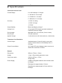
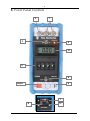
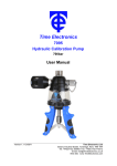
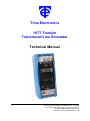
Time Electronics
1077 Transim
Transducer/Line Simulator
Technical Manual
V1.1 04/11/10
Time Electronics Ltd
Botany Industrial Estate, Tonbridge, Kent, TN9 1RH
Tel: +44(0)1732 355993 Fax: +44(0)1732 770312
Email: [email protected]
Web Site: www.TimeElectronics.com
2
C ontents
1.
Introduc tion ...................................................................................................... 3
2.
S pec ific ations ................................................................................................... 4
3.
F ront P anel C ontrols ........................................................................................ 6
4.
Operation .......................................................................................................... 8
5.
6.
7.
4.1.
Principle of Operation of the 2 Wire 4/20mA System ..................................... 8
4.2.
Checking/Calibrating the Transducer ............................................................. 9
4.3.
Checking/Calibrating the Recorder ................................................................. 9
4.4.
Test/Calibrate Current Meter/Recorder and Power Unit................................. 9
4.5.
Setting the Output Voltage ............................................................................... 9
4.6.
Operation as a Current Load.......................................................................... 10
4.7.
Operation as a Current Source ...................................................................... 11
4.8.
Operation as a Line Simulator ....................................................................... 12
4.9.
Recharging ...................................................................................................... 13
C irc uit Des c ription ......................................................................................... 14
5.1.
Power Supply .................................................................................................. 14
5.2.
Mains Re-charger............................................................................................ 14
5.3.
Circuit Module and Range Switch ................................................................. 14
Maintenanc e ................................................................................................... 15
6.1.
Dismantling the Instrument ........................................................................... 15
6.2.
Fuse Replacement .......................................................................................... 15
6.3.
Repair .............................................................................................................. 15
6.4.
Calibration ....................................................................................................... 16
G uarantee & S ervic ing ................................................................................... 18
All Time Electronics' instruments are subject to continuous development and improvement and in
consequence may incorporate minor detail changes from the information contained herein.
1077 Technical Manual
Page |2
3
1. Introduc tion
The 1077 is a portable, hand-held instrument designed for the testing and simulation of
current transducers. The three operating modes of the 1077 are:-
1. A precision adjustable current load, capable of taking 100mA from a 24V supply.
2. A DC 24 volt supply with a 0-20mA output current display.
3. A precision adjustable current source capable of driving up to 100mA through 250
ohms (or 20mA through 2,000 ohms).
The unit is powered from internal rechargeable cells and is supplied in a carry case making
the 1077 ideal for field or site measurements.
1077 Technical Manual
Page |3
4
2. S pec ific ations
Current Source and Load
Current Range:
0 to 100 milliamps in 3 ranges.
0 - 99.99mA in 10 uA steps.
0 - 9.999mA in 1 uA steps.
0 - 999.9uA in 0.1 uA steps.
Accuracy:
+/-0.02% of setting.
+/-0.02% of range.
+/-0.02uA
Output Stability:
Better that 60ppm per deg.C.
Voltage Limit:
A front panel LED indicator provides indication of
insufficient terminal voltage.
Drive Voltage:
Adjustable from 14 to 40 volts. (Source mode)
Drive Power:
2.5 watts maximum.
Applied Voltage:
3 volts minimum to 40 volts maximum. (Load mode)
Transducer Line Simulation
24 Volt Output:
Variable between 14 and 40 volts by rear panel
control. Current limited to 100 milliamps max. or
2.5 watts.
Output Current Meter:
A 3.5 digit LCD meter displays output current up to
20mA with a resolution of 100uA.
General
Dimensions:
200mm x 75mm x 110mm.
Weight:
1.1kg. (1.5kg including protective cover).
Carry Case option:
210mm x 87mm x 117mm
Weight 300g.
Power Supply:
8 NiMH rechargeable batteries with external mains
re-charger.
Recharge time approximately 12 hours.
Operating time approximately 10 hours before a
recharge.
1077 Technical Manual
Page |4
5
Page left blank intentionally
1077 Technical Manual
Page |5
6
3. F ront P anel C ontrols
2
1
3
6
10
5
9
ON/OFF
4
7
8
1077 Technical Manual
11
Page |6
7
1.
Output Terminals
The output current is available on the two front panel terminals which are suitable for
normal wire compression or 4mm plug insertion.
2.
Case Terminal
Connected only to the instrument case and is isolated from the circuitry. The case
provides an overall electrostatic screen and can be earthed as required to improve
rejection of noise pick-up.
3.
Output On-Off Switch
Disconnects the output terminals from the 1077 circuitry. The 'Off' position provides
an open circuit on the output terminals.
4.
Range and Supply On-Off Switch
Four press button switches with interlocking on the 3 range buttons to ensure that
only one range can be selected at one time.
5.
Digit Switch
Four decade thumbwheel switches with 0-9 positions on each decade.
6.
Voltage Limit Indicator
An L.E.D. display which indicates when the 1077 has insufficient voltage across its
output terminals to sink or drive the set current.
Important Note:
Voltages in excess of 40 volts across the output terminals will cause an
overload condition in the 1077 and the output fuse will blow.
7.
Battery Level Indicator
Located on the side of the instrument and continuously monitors the battery voltage.
A minimum mark indicates when the batteries need recharging.
8.
Re-charger Socket
Also located on the side of the instrument. The mains re-charger is a separate unit
and the output is via a flying lead with a non-reversible plug. Charge current is 50
mA and recharge time is 12-14 hours.
9.
Load/Line/Source Switch
A three position switch which selects the function of the 1077.
10. LCD Meter
Displays the output current taken when operating in 'Line' mode (in Load/Source
mode displays Zero).
11. Output Voltage Adjustment
Sets maximum open circuit voltage in 'Source' mode and output voltage in 'Line'
mode (normally set for 24V output).
1077 Technical Manual
Page |7
8
4. Operation
4.1. Principle of Operation of the 2 Wire 4/20mA System
To fully understand the operation of the 1077 a working knowledge of the 4/20mA system is
required. A short explanation follows:
The basic requirements for any transducer with remote display is:
a) To use as few wires as possible.
b) That errors are not introduced into the signal from the transducer by the effects of
interference or voltage drop due to lead resistance.
c) To supply power to the transducer to enable amplifiers to be built into the transducer
when the signal produced by the sensing element is too small to be transmitted
without amplification.
In the 4/20mA system the transducer is supplied with D.C. power by a 2-wire line. The
transducer takes a current from the line proportional to the stimulus (pressure, temperature,
etc.). By measuring the current flowing in the line the output of the transducer can be
monitored.
As the signal is transmitted as a current, lead resistance and voltage drip do not affect the
accuracy. Hence the basic requirements are fulfilled using just two wires - the minimum
possible.
To enable a certain amount of standardisation and to compensate for voltage drop and
variation in the supply, transducers are designed to operate over a wide voltage range
(usually between 15-30 volts) and to take a 'Zero' current of 4mA and a 'full scale' current of
20mA.
The simplest 4/20mA current loop system is of 3 parts, although often 2 parts are
incorporated in the same box. The 3 main parts are:
1. D.C. Power supply usually 24V.
2. 4-20mA current meter/recorder
3. The transducer.
The DC power supply generates the drive power for the system and can be considered as a
battery.
The 4/20mA meter/recorder can be a passive moving coil mA meter with a zero offset, to
obtain a reading current must be injected.
The transducer completes the loop and allows a current to flow round the loop dependent
on the level of stimulus to the transducer, it can almost be considered as a potentiometer
changing in resistance to let between 4 and 20mA flow.
The 1077 can be used to calibrate/test any part of this system, by using the 1077 in its 3
operating modes.
1077 Technical Manual
Page |8
9
4.2. Checking/Calibrating the Transducer
By selecting the 'line' simulation mode on the 1077, the 1077 acts as the 24V D.C. supply
and the current meter, any current taken from the 24V across the 1077 terminals will be
registered on the L.C.D. meter.
The current taken by a transducer can therefore be easily checked by connecting the
transducer directly to the 1077 and then reading the current shown on the meter.
4.3. Checking/Calibrating the Recorder
By selecting 'Source' mode the 1077 will supply the necessary voltage to drive the current
set on the thumbwheel switches through the recorder, should the voltage required to drive
the set current be greater than the maximum voltage the 1077 can produce, the 'voltage
limit' light illuminates indicating that the set current is not being driven.
The current meter/recorder can be checked by driving in set currents and observing the
corresponding deflection.
4.4. Test/Calibrate Current Meter/Recorder and Power Unit
The 'Load' mode of the 1077 simulates the transducer in which the current set on the
thumbwheel switches is taken from an externally applied voltage, which must be between 3
and 30 volts. In this mode it is possible to disconnect the transducer from the loop and
connect, in its place, the 1077; the current registered on the recorder being the current set
on the 1077. In this way the power unit, recorder and wiring of the loop are checked.
4.5. Setting the Output Voltage
The maximum terminal voltage the 1077 will supply in any mode can be set by the ‘Output
Voltage Control’.
To adjust remove the 1077 from the carrying case and locate the Output Voltage adjustment
to the right of the Battery Level Indicator (a small screwdriver will be necessary if adjustment
is required).
Turn on the 1077 and select line mode. Turn the output on and measure the terminal
voltage with a voltmeter. Adjust to new voltage with output voltage control if required.
Note 1: This control also sets the maximum terminal voltage that will be applied in the
Source mode.
Note 2: The maximum output voltage at 100mA will be 24V (.1A x 24V – 2.4 watts)
regardless of the setting of the Output Voltage control.
1077 Technical Manual
Page |9
10
4.6. Operation as a Current Load
(Transducer Simulation)
SUPPLY
-
+
I mA
LINE
As a current load
the 1077 Will draw the
current set from the line.
1.
Turn on 1077, check battery level and select current range nearest to load current
required.
2.
Select the ‘load’ position of the load/line/source switch.
3.
Connect output terminals to the line:
•
•
Positive terminal (red) to positive line.
Negative terminal (black) to negative line.
4.
Set load current required on the digit switch.
5.
Turn output switch ‘ON’.
Warning
Any attempt to connect the 1077 to a line with more than 40 volts potential on it will
cause the 1077 output fuse to blow.
Note: If V limit LED illuminates the 1077 has insufficient drive voltage to output the current
set. See 'Output Voltage Control' Section.
1077 Technical Manual
P a g e | 10
11
4.7. Operation as a Current Source
I mA
As a current source the 1077 will
supply the set current to the load
1. Check the setting of the output voltage control as in Section 3.1.
2. Turn on and select ‘Source’ mode.
3. Select most suitable range and set output on digit switches.
4. Connect ‘Load’ and turn output switch ON.
Note: If V limit LED illuminates the 1077 has insufficient drive voltage to output the current
set. See ‘Output Voltage Control’ Section.
1077 Technical Manual
P a g e | 11
12
4.8. Operation as a Line Simulator
Transducer
I mA
24 Volts
As a current source the 1077 will
supply the set current to the load
24 Volt Line
In this mode the 1077 supplies a constant 24V. The current taken by the transducer can be
accurately measured on the 1077:
1. Turn on the 1077 and select the line position of the load line source switch.
2. Turn the output switch ON.
3. Read output current on the LCD display.
1077 Technical Manual
P a g e | 12
13
4.9. Recharging
To charge the 1077 first turn off the 1077 then connect the charge to the recharge socket on
the end of the 1077. (The connector is polarized to prevent accidental reversal).
Plug charger into mains supply.
If the 1077 is left ON when recharging the cells will not fully recharge.
The 1077 contains Nickel Metal Hydride batteries which are monitored by the battery level
indicator at the end of the unit. The unit will take approximately 12-14 hours to fully recharge
the batteries. The 1077 may be left on charge continuously without damaging the batteries.
Important:
Always recharge when the battery level indicator shows minimum.
1077 Technical Manual
P a g e | 13
14
5. C irc uit Des c ription
5.1. Power Supply
The batteries and power supply circuitry is located on the bracket which is mounted below
the battery level indicator. Eight AA size rechargeable batteries provide an output of 9.6
volts D.C. to power a switched mode regulator which generates all the regulated supplies for
the 1077 and the adjustable output voltage.
The rechargeable battery is protected by a miniature fuse mounted on the board. The fuse
is rated at F1A and has dimensions of 20mm length by 5mm diameter.
5.2. Mains Recharger
The mains recharger is a separate unit and enables the 1077 batteries to be fully charged in
12-14 hours. An overnight charge is usually adequate. The mains input is 200-240 volts
50/60 Hz standard. 100-120 volts, 50/60 Hz are available but should be specified on
ordering. The plug and socket are shaped to ensure that they cannot be connected in the
wrong polarity.
5.3. Circuit Module and Range Switch
The 1077 active circuitry and range switch are located on a printed circuit board which is
mounted on the front panel. Connection to the P.C.B. is via a 9 pin connector. The active
circuitry is encapsulated and contains the precision reference circuitry and output stage.
Four calibration trimmers are mounted on the P.C.B. (ref. section 6.4).
A replacement procedure should be adopted in the case of failure.
1077 Technical Manual
P a g e | 14
15
6. Maintenanc e
6.1. Dismantling the Instrument
Remove rubber protection boot and then removal of four 2.0mm CSK screws enables the
blue cover to be taken off which provides access to all parts of the instrument.
The range switch assembly can be removed by disconnecting the 9-pin connector and
removing the two front panel locating screws.
6.2. Fuse Replacement
The power supply and output fuses are easily accessible on removing the cover panel (6.1).
Fuses are rated at F1A (F1) and F250mA (F2) and have dimensions 20mm length by 5mm
diameter. The fuses are available from Time Electronics Ltd. or your local supplier.
Alternative types of the same dimensions and ratings may be used.
6.3. Repair
Due to the precision nature of many of the components used in the 1077, they are not
readily available to enable the customer to undertake repairs.
Important Note:
No repair work should be undertaken by the customer while the 1077 is under
warranty. Such work may invalidate the warranty.
Overload conditions can cause the fuses to blow and the following conditions will be
observed:
1. The instrument is inoperative and the battery level indicator does not operate when the
1077 is switched on. A possible cause is that the power supply fuse F1 is blown (see 6.2).
2. The battery level indicator displays but no output appears at the output terminals. A
possible cause is that the output fuse F2 is blown.
Fuse Location
BATTERY PACK
MODULE
J2
BATTERY PACK
F1 F1A
F2 F250mA
1077 Technical Manual
P a g e | 15
16
6.4. Calibration
The 1077 is calibrated when it leaves the factory and should not require further adjustment
for at least 12 months unless the circuit module or any of the calibration determining
components have been changed.
Before attempting recalibration it is important to ensure that the correct equipment is
available.
Equipment Required:
1. D.C. voltage source power supply for 24V at 100mA.
2. Precision DMM (0.01%) with 100mA, 10mA and 1mA current ranges and 100 volt range.
A. Calibration of Current Source/Sink
Zero Adjustment
Note:
Check the battery conditions
before recalibration.
Turn the 1077 ON and select
‘Source’ mode with the function
switch.
Select 100mA range on the 1077
and set the digit switch to 0005.
Connect the output of the 1077 to
the DMM.
Select the 1mA range on the
DMM.
Turn the 1077 output ON and
adjust zero trimmer to give 50uA
reading on the DMM.
10mA Range F.S.D Adjustments
Select 10mA range on DMM.
Select 10mA range on 1077 and the digit switch set to 9999.
Adjust VR2 (10mA trimmer) to bring within required accuracy.
1mA Range F.S.D. Adjustments
Select 1mA range on DMM.
Select 1mA range on 1077.
Adjust VR4 (1mA trimmer) to bring within required accuracy.
100mA Range F.S.D. Adjustments
Select 100mA range on DMM.
Select 100mA range on 1077 and the digit switch set to 9999.
Adjust VR3 (100mA trimmer) to bring within required accuracy.
B. Load Function Tests
1077 Technical Manual
P a g e | 16
17
Set the 1077 to Load function with 10mA range and digit switch set to 9999. Connect the
24V supply to the 1077 through the DMM. Check the 1077 takes 10mA from the 24V
supply.
C. Linearity
The linearity of the output is not adjustable and is determined by the precision resistors
mounted on the digit switch. These have been selected and adjusted in the factory and
should not require further alteration.
D. LCD Current Meter F.S.D
1. Set the 1077 to line mode and take
20mA from the output.
2. Adjust VR1 on LCD meter for
20,00 milliamps.
1077 Technical Manual
P a g e | 17
18
7. G uarantee & S ervic ing
Guarantee Period
This unit is guaranteed against defects in materials and workmanship for a period of one
year from its delivery to the customer.
We maintain comprehensive after sales facilities and the unit can, if necessary be returned
to us for servicing. During this period, Time Electronics Ltd will, at its discretion, repair or
replace the defective items. For servicing under guarantee, the instrument type and serial
number must always be quoted, together with details of any fault and the service required.
The purchaser of the instrument must prepay all shipping charges. Time Electronics Ltd will
pay return shipping charges.
This guarantee is void if servicing has been attempted by an unauthorised person or agent.
If, during the guarantee period, failure is due to misuse or abuse of the unit, the repair will
be put in hand without delay and charged unless other instructions are received.
Please note that if you require a new UKAS Certificate during the warranty period, this will
be charged at the current rate on our price list.
Service After Guarantee Period
Even after the guarantee period has expired, Time Electronics Ltd., can still service your
instrument. As the manufacturer, we have the specialised knowledge needed to keep your
instrument in peak condition and we also maintain a comprehensive spare parts service.
Please enclose details of the service required and your full company details including a
contact name when returning for servicing.
Returning Instruments
When returning instruments, please ensure that they have been adequately packed,
preferably in the original packing supplied. Time Electronics Ltd will not accept
responsibility for units returned damaged. Please ensure that all units have details of
the service required and all relevant paperwork.
Send the instrument, shipping charges paid to:-
Time Electronics Ltd
Botany Industrial Estate, Tonbridge, Kent, TN9 1RH
Tel: +44(0)1732 355993 Fax: +44(0)1732 770312
Email: [email protected]
Web Site: www.timeelectronics.com
Disposal of your old equipment
1. When this crossed-out wheeled bin symbol is attached to a product it means the product
is covered by the European Directive 2002/96/EC.
2. All electrical and electronic products should be disposed of separately from the
municipal waste stream via designated collection facilities appointed by the government
or the local authorities.
3. The correct disposal of your old appliance will help prevent potential negative
consequences for the environment and human health.
4. For more detailed information about disposal of your old appliance, please contact your
city office, waste disposal service or return to Time Electronics.
1077 Technical Manual
P a g e | 18