1
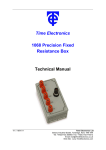
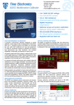
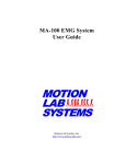
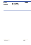
Time Electronics
1017 DC Multifunction
Voltage/Current/Resistance Calibrator
Technical Manual
V1.2 01/11/10
Time Electronics Ltd
Botany Industrial Estate, Tonbridge, Kent, TN9 1RH
Tel: +44(0)1732 355993 Fax: +44(0)1732 770312
Email: [email protected]
Web Site: www.TimeElectronics.com
2
C ontents
1.
Introduc tion ............................................................................................................ 3
1.1.
General Description................................................................................................ 3
1.2.
Specifications ......................................................................................................... 4
1.3.
Circuit Description.................................................................................................. 5
1.4.
Power Supply Description ..................................................................................... 5
2.
F ront P anel C ontrols .............................................................................................. 6
3.
Operation ................................................................................................................ 7
4.
5.
3.1.
Preparing for Use.................................................................................................... 7
3.2.
Using the 1017 ........................................................................................................ 7
3.3.
Thermal EMF's ........................................................................................................ 7
3.4.
Using the Deviation Control ................................................................................... 7
C alibration .............................................................................................................. 8
4.1.
Calibrating the 1017................................................................................................ 8
4.2.
Zero Adjustment ..................................................................................................... 8
4.3.
Calibrating the Full Scales ..................................................................................... 9
4.4.
Calibrating the Deviation Control .......................................................................... 9
G uarantee & S ervic ing ......................................................................................... 10
All Time Electronics' instruments are subject to continuous development and improvement and in
consequence may incorporate minor detail changes from the information contained herein.
1017 Technical Manual
2
3
1. Introduction
1.1. General Description
The 1017 is a high performance portable calibrator for use in the field or laboratory.
With voltage ranges from 10nV to 100V, current from 100nA to 100mA and resistance from
10mΩ to 10kΩ, it makes the 1017 an extremely versatile instrument, capable of calibration
or simulation.
The digital deviation control allows the output to either increase or decrease directly in a
percentage from 0.001% to 0.999%. This is a useful feature for checking the accuracy of
difficult scales.
Long term stability is guaranteed by the use of high quality components and the latest in
resistor technology.
The 1017’s basic reference source is a specially aged, computer selected, precision
reference diode. The diode provides the input to the instruments active circuitry which
incorporates several high performance chopper stabilised amplifiers with a zero stability of
less than 0.5uV per°C and a warm up time of less than 1 minute.
The precision resistors used in the 1017 are high performance types with temperature ratio
matching of less than 2ppm per °C.
The output terminals are low thermal E.M.F. types, typical E.M.F. of less than 0.2uV per °C.
The 1017 can be powered from either the mains or the internal rechargeable battery pack.
The batteries are automatically recharged when the mains supply is connected. A front
panel battery level indicator displays the batteries state of charge.
Output polarity can be reversed via a switch on the front panel.
1017 Technical Manual
3
4
1.2. Specifications
Outputs:
Voltage
Range:
0 – 100V in 5 Ranges
0 – 100mA in 1 Range
0 – 10kΩ in 1 Range
0 – 9.99999mV in 10nV steps
0 – 99.9999mV in 100nV steps
0 – 999.999mV in 1uV steps
0 – 9.99999V in 10uV steps
0 – 99.9999V in 100uV steps
Accuracy:
10mV range
100mV range
1V range
10V range
100V range
0.02% of setting +/- 0.005% of range
0.01% of setting +/- 0.004% of range
0.005% of setting +/- 0.002% of range
0.005% of setting +/- 0.002% of range
0.01% of setting +/- 0.004% of range
Output Resistance:
100mV to 10V
10mV and 100V
<200mΩ
<1Ω
Output Current:
100mV to 10V
100V
10mV
150mA
10mA
Limited by 1Ω Output resistance
Current
Range:
Accuracy:
Drive Voltage:
0-99.9999mA
100mA range
10V Maximum
in 100nA steps
0.02% of setting and 0.004% of range
Resistance
Range:
Accuracy:
Power Rating:
End Resistance:
0 – 9.99999kΩ in 10mΩ steps
0.05% of full scale
250mW per Resistor
< 200mΩ
All specification +/- 3uV.
Deviation Control (Only on Voltage and Current)
Range:
0.001% to 0.999% in 0.001% steps
Accuracy:
0.5% Accuracy
Stability
Less than 10ppm/°C on all ranges.
Less than 5ppm/Day at constant temperature
Less than 15ppm/90 days
Less than 25ppm/Year
Output Noise
Output Noise (0.1Hz to 10Hz) - Typically 3ppm.
Power Supply
The 1017 can be used continuously from a 220V / 240V 50 / 60Hz (110V / 120V to order)
mains supply or from the internal rechargeable Ni-Cad battery pack. A front panel meter
indicates the state of charge at all times.
1017 Technical Manual
4
5
Dimensions & Weight
Dimensions – 290mm x 250mm x 110mm
Weight – 2.4Kg
Operating Temperature
0°C to +50°C max. For optimum performance and stability the 1017 should be stored and
used in temperatures between 15°C and 25°C.
1.3. Circuit Description
The calibrator employs a temperature compensated zener diode as the basic reference
source. This provides the input to an FET chopper amplifier system which operates in a feed
– back stabilised mode, and has a gain value determined by a set of precision wire-wound
resistors which are selected by a 6 decade thumbwheel switch. The output voltage is
variable from 0V to 99.9999V in 6 ranges.
An output resistance of typically 150mΩ is maintained on all ranges excluding the 100V
range where the output resistance is 1Ω. The maximum output current that can be drawn on
the 10V and 1V ranges is automatically limited to approximately 150mA, or 15mA on the
100mV range. It must be noted that the current on the 10mV range is limited by a 1Ω
resistance. The output current on the 100V range is 10mA.
The 100V output is generated by driving a step-up transformer with the ’chopped’ D.C.
output from the output of the module. Feedback around the complete amplifier regulates the
output to the set output value.
When the 100mA range is selected, the output current is sensed by a precision resistor.
The voltage generated across this resistor is used to control the output drive voltage, so
regulating the output current.
The resistance range operates by directly switching the thumbwheel switch to the output
terminals.
The deviation control operates by injecting a current into the reference circuitry which either
increases or decreases the reference voltage.
To ensure complete reliability of the thumbwheel switch, double pole gold plated contacts
are used for each position – even if a contact fails, the 1017 will continue to work correctly.
1.4. Power Supply Description
The power supply for this unit is via a Time Electronics PU2 power supply. This unit
provides a battery power supply for portable use, which is automatically charged when
mains operation is used. This is mounted on the rear panel of the 1017. The power supply
is set for 220V – 240V AC mains unless otherwise specified.
When the mains is connected, the charging circuitry provides the correct charge current (40
– 45mA) for the battery and automatically reduces this to at trickle charge (3 – 4mA) when
the battery is fully charged. This means that it is impossible to over-charge the battery.
Approximately 30 – 40 hours use may be obtained between charges, depending on the
output setting.
1017 Technical Manual
5
6
2. Front Panel Controls
1
2
3
4
5
6
7
8
1 – Output Terminals.
2 – Case Terminal.
3 – Reverse / Off / Normal Switch, Selects the output polarity.
4 – Power On / Off Switch. Indication is shown by the Battery Level Indicator.
5 – Range Select Switch. Selects the output maximum output.
6 – Range Output Digit Switch. Selects the value of output.
7 – Deviation Digit Switch. Selects the value of Deviation.
8 – Battery Level Indicator. Shows the state of charge of the batteries.
9 – Positive / Off / Negative Deviation Control. Applies a Positive or Negative
Deviation to the output as a percentage.
1017 Technical Manual
6
9
7
3. Operation
3.1. Preparing for Use
Before using the 1017, you must first check to see if the battery level indicator shows that
the batteries are in a good state of charge. If the indicator shows that they are low then you
must recharge them by plugging the 1017 into the mains supply. It will take approximately
12 – 14 hours to fully recharge the battery pack. You may of course use the 1017 when it is
plugged into the mains supply irrespective of the battery state. The batteries should also be
checked during operation.
3.2. Using the 1017
Firstly, select the correct range on the range select switch ensuring that the output polarity
switch is ’OFF’ and that nothing is dialled up on the digit switch. Then dial up the required
value on the digit switch. The output may then be supplied to the unit under test by selecting
the output polarity switch.
Note: When the output switch is set to the ’OFF’ position, there is a short circuit on the
output terminals.
Caution must be exercised when using the 100V range against possible electrical shock.
3.3. Thermal EMF's
When using the 1017 to provide a precision voltage of less than 1mV, care must be taken to
avoid Thermal EMF’s. These occur where temperature differences are present at the
junctions of dissimilar metals, e.g. – A normal solder to copper junction has a thermal EMF
of approximately 3uV/°C. Errors in the 1017 under stable temperature conditions are
typically less than +/- 0.2uV/°C.
3.4. Using the Deviation Control
Note: The digital deviation control has no effect if used on the resistance range.
To apply a percentage deviation to the output, select either positive or negative deviation
with the control switch and dial up the percentage deviation required on the digit switch.
Alternatively, if the output is set to the correct value and the reading on the U.U.T. reading
differs from this, adjust the deviation control to give the required value. The error can then
be read directly, as a percentage, from the deviation control.
1017 Technical Manual
7
8
4. Calibration
4.1. Calibrating the 1017
The 1017 can be calibrated with a high accuracy D.M.M. with D.C. voltage, current and
resistance ranges with a specification of at least 4 times greater than that of the 1017’s
specifications.
Calibration is best carried out on fully charged batteries without the mains supply connected
to ensure that no mains supply interference takes any effect on the readings.
4.2. Zero Adjustment
Range
Allowance
Adjust Pot
1V
6µV
1V ZERO ON MODULE
1017 Technical Manual
8
9
4.3. Calibrating the Full Scales
After checking the zero settings you may then calibrate the full scales. Set the digit switch to
’999999’.
Adjust the 1V Full Scale with the ’CAL’ trimmer which is on the potted module.
Adjust this to read 1V to within 20uV.
Adjust the 10V F.S. trimmer, VR5, to read 10V to within +/- 200uV.
Adjust the 100mV & 10mV F.S. trimmer VR3, to read 100mV to within +/ - 4.3µV
(Done on 100mV Range)
Check 10mV F.S. is within 1.3µV.
Adjust the 100V F.S. trimmer, VR6, to read 100V to within +/- 3.5mV.
Adjust the 100mA F.S. trimmer, VR7, to read 100mA to within +/- 6uA.
4.4. Calibrating the Deviation Control
Set the output to the 1V on the 1V range and set the deviation to +0.999%. Adjust the output
using the + Deviation trimmer, VR9, to read 1.01V to within 5mV.
Leaving the output at 1V on the 1V range, set the deviation to –0.999%. Adjust the output
using the – Deviation trimmer, VR8, to read 0.99V to within 5mV.
The Calibration procedure is now complete.
1017 Technical Manual
9
10
5. Guarantee & Servicing
Guarantee Period
This unit is guaranteed against defects in materials and workmanship for a period of one
year from its delivery to the customer.
We maintain comprehensive after sales facilities and the unit can, if necessary be returned
to us for servicing. During this period, Time Electronics Ltd will, at its discretion, repair or
replace the defective items. For servicing under guarantee, the instrument type and serial
number must always be quoted, together with details of any fault and the service required.
The purchaser of the instrument must prepay all shipping charges. Time Electronics Ltd will
pay return shipping charges.
This guarantee is void if servicing has been attempted by an unauthorised person or agent.
If, during the guarantee period, failure is due to misuse or abuse of the unit, the repair will be
put in hand without delay and charged unless other instructions are received.
Please note that if you require a new UKAS Certificate during the warranty period, this will
be charged at the current rate on our price list.
Service After Guarantee Period
Even after the guarantee period has expired, Time Electronics Ltd., can still service your
instrument. As the manufacturer, we have the specialised knowledge needed to keep your
instrument in peak condition and we also maintain a comprehensive spare parts service.
Please enclose details of the service required and your full company details including a
contact name when returning for servicing.
Returning Instruments
When returning instruments, please ensure that they have been adequately packed,
preferably in the original packing supplied. Time Electronics Ltd will not accept
responsibility for units returned damaged. Please ensure that all units have details of the
service required and all relevant paperwork.
Send the instrument, shipping charges paid to:-
Time Electronics Ltd
Botany Industrial Estate, Tonbridge, Kent, TN9 1RH
Tel: +44(0)1732 355993 Fax: +44(0)1732 770312
Email: [email protected]
Web Site: www.TimeElectronics.com
Disposal of your old equipment
1. When this crossed-out wheeled bin symbol is attached to a product it means the
product is covered by the European Directive 2002/96/EC.
2. All electrical and electronic products should be disposed of separately from the
municipal waste stream via designated collection facilities appointed by the
government or the local authorities.
3. The correct disposal of your old appliance will help prevent potential negative
consequences for the environment and human health.
4. For more detailed information about disposal of your old appliance, please contact
your city office, waste disposal service or return to Time Electronics.
1017 Technical Manual
10