Download 1021 User Manual - Time Electronics
Transcript
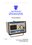
Time Electronics
1021 Current Source
With Null Measuring Facility
Technical Manual
V1.4 14/12/10
Time Electronics Ltd
Botany Industrial Estate, Tonbridge, Kent, TN9 1RH
Tel: +44(0)1732 355993 Fax: +44(0)1732 770312
Email: [email protected]
Web Site: www.TimeElectronics.com
2
C ontents
1.
Introduc tion ........................................................................................................ 3
1.1.
General Description............................................................................................ 3
1.2.
Specifications ..................................................................................................... 4
2.
C ontrols .............................................................................................................. 5
3.
Operation ............................................................................................................ 7
3.1.
Preliminaries ....................................................................................................... 7
3.2.
Normal Operation ............................................................................................... 7
3.3.
Measurement of Current .................................................................................... 7
3.4.
Voltage Compliance Adjustment
3.5.
Overload Conditions .......................................................................................... 7
3.6.
Battery Recharging............................................................................................. 7
- V O/P...................................................... 7
4.
E lec tric al Nois e P ic k-Up .................................................................................... 8
5.
C irc uit Des c ription ............................................................................................. 9
6.
7.
8.
5.1.
Power Supply ...................................................................................................... 9
5.2.
Mains Recharger ................................................................................................. 9
5.3.
Circuit Module and Range Switch ..................................................................... 9
Maintenanc e and R epair .................................................................................. 10
6.1.
Maintenance ...................................................................................................... 10
6.2.
Repair ................................................................................................................ 10
R ec alibration .................................................................................................... 11
7.1.
Calibration Procedure ...................................................................................... 12
7.2.
Linearity ............................................................................................................ 13
G uarantee & S ervic ing ..................................................................................... 14
All Time Electronics' instruments are subject to continuous development and improvement and in
consequence may incorporate minor detail changes from the information contained herein.
1021 Technical Manual
2
3
1. Introduc tion
1.1. General Description
• 100mA output with overload protection
• 0.02% Accuracy
• Wide range of applications
• Safety terminals
• Removable protective boot
• Battery level indicator
The 1021 is a precision DC Current Source suitable for calibration and test applications from
100nA up to 100mA.
The 100mA output with overload protection is based on the popular Time Electronics type
1007 millivolt source and incorporates many of the well-proven features. The instrument is
overload protected and a front panel indicator shows when insufficient drive voltage is
available. The terminal output voltage is adjustable between 14 volts and 40 volts, with a
maximum output power of 2.4 watts.
The unique circuit design ensures that it stays well within specification for at least 12
months. Variation with temperature is better than 60 ppm per ºC, and typically better than
20 ppm per hour at constant temperature. To improve the switch reliability, additional backup contacts have been used – even if a contact fails, the 1021 will still operate correctly.
The accuracy and stability are such that a wide range of applications are possible. In the
process industries it may be used to test and calibrate current sensitive transducers, and
their associated indicating and recording instruments. The semiconductor industry requires
constant current sources for parameter measurements. It may also be used to measure DC
current accurately by using the null facility to back off the unknown current. Resolution of
1µA is possible.
The 1021 is housed in a robust metal case and a removable protective boot is supplied as
standard. The front panel safety terminals are compatible with 4mm shrouded plugs, as well
as standard plugs, bare wires, and spade terminals.
Rechargeable batteries give portable operation and a mains recharger is supplied with the
unit. Complete recharge time is 10-12 hours although sufficient charge for a few hours
operation can be obtained with only 1/2 hours’ charge. Overnight recharge is sufficient to
fully charge the batteries, which give up to 10 hours of typical operation. The mains
recharger is supplied as standard with the 1021 and connects with a socket on the top
panel.
1021 Technical Manual
3
4
1.2. Specifications
Output:
0-100mA in 3 ranges:
(1)
(2)
(3)
0-99.99mA in 10uA steps
0-9.999mA in 1uA steps
0-999.9uA in 0.1uA steps
Accuracy:
+/- 0.02% of setting +/- 0.02% of range
+/- 0.02uA
Drive Voltage:
Adjustable between 14 and 40 volts.
Maximum output power 2.4 watts.
Out of Limit Warning:
A front panel indicator provides indication of insufficient drive
voltage.
Output Polarity:
Normal or Reverse, switch selected. A centre OFF position
provides an open circuit.
Output Stability:
Better than 60 ppm per ºC (-10 ºC to +50 ºC). Better than 25
ppm per hr (at constant temperature).
Null Sensitivity:
Adjustable from ±25mA to ±25uA.
Load Regulation:
Better than 20 ppm per volt change in output.
Power Supply:
8 NiMH rechargeable batteries with external mains re-charger.
Standard mains voltage is 220-250V 50/60Hz.
100-125V 50/60Hz is available but must be specified on order.
Dimensions:
200 x 75 x 110mm
215 x 100 x 120mm including protective boot
Weight:
1kg
1.4kg including protective boot
Optional Extras:
Leather Carry Case (9027)
Factory Calibration Certificate (9153)
UKAS Calibration Certificate (9105)
Additional Rechargeable Battery Packs:
230V mains charger and 8 NiMH cells (9529)
110V mains charger and 8 NiMH cells (9528)
1021 Technical Manual
4
5
2. C ontrols
1
4
2
5
3
6
7
8
9
10
12
11
1021 Technical Manual
5
6
1. Output Terminals
Output current is available on two front panel terminals which are suitable for either wire
compression or 4mm 'wander' plug insertion.
2. Case Terminal
This is connected to the instrument case only and is isolated from the circuitry. The case
provides an electrostatic screen and can be earthed for rejection of noise pick-up.
3. Sensitivity Control
A continuously variable control for adjusting the Null indicator sensitivity. The range of
adjustment is from 25mA (fully anti-clockwise) to 25uA (fully clockwise).
4. Polarity Switch
Normal or reverse polarity is selected by a toggle switch. The centre position is OFF which
provides an open circuit on the output terminals.
5. Voltage Limit Indicator
An LED which indicates when the 1021 is unable to supply sufficient drive voltage to
maintain the set output current, e.g. the maximum drive voltage of the instrument.
6. LED Null Indicator
Used for reading off an unknown current when the instrument is used in the Null mode.
7. Digit Switch
Four-decade thumbwheel switch with 0 to 9 selections on each decade.
8. Source/Null Switch
A two position toggle switch for selecting the mode of operation. In the Source position the
instrument operates as a current source. In the Null position the instrument is used for the
measurement of current.
9. Supply On/Off Switch and Range Switches
Four press button switches with interlocking on the three range switches to ensure that only
one range can be selected at one time.
10. Battery Level Indicator
Located on the top end of the 1021 this continuously monitors the battery voltage. A
minimum mark indicates when the batteries require recharging.
11. Recharge Socket
This is also located on the top end of the instrument. The mains recharger is a separate
unit, the output of which is supplied via a flying lead fitted with a non-reversible plug.
Recharge time is between 12 and 16 hours.
12. V/OP The instrument is overload protected and a front panel indicator shows when
insufficient drive voltage is available (see 5 above). Drive output voltage is adjustable
between 14 volts and 40 volts, with a maximum output power of 2.4 watts.
CAUTION
UNDER NO CIRCUMSTANCES MUST AN ADDITIONAL VOLTAGE BE CONNECTED IN
SERIES WITH THE OUTPUT OF THE 1021 IN AN ATTEMPT TO INCREASE THE
VOLTAGE CAPABILITY AS THIS WILL CAUSE DAMAGE TO THE OUTPUT
CIRCUITRY.
1021 Technical Manual
6
7
3. Operation
3.1. Preliminaries
The 1021 is supplied complete with rechargeable batteries (housed in the instrument) and a
mains charger. Before operation, the batteries should be checked on the battery level
indicator. It is important to recheck the battery condition when the instrument is supplying
currents in excess of a few tens of mA, since the additional load may reduce the battery
voltage to below the minimum level.
3.2. Normal Operation
Using the specification together with the front panel controls makes the operation selfexplanatory. It is important to understand the voltage capability and the voltage limit
indicator of the instrument to ensure that requirements are within limits.
3.3. Measurement of Current
1. Select NULL on the front panel function switch.
2. Select NORM output.
3. Adjust SENS fully anti-clockwise (minimum sensitivity).
4. Select RANGE consistent with the current to be measured.
5. Connect the unknown current such that it flows into the + ve terminal.
6. Adjust the digit switch and sensitivity control for null balance on the LED indicator
(green centre LED).
7. When balance at the required sensitivity is reached, the value of the unknown current
equals the digit switch setting.
3.4. Voltage Compliance Adjustment
- V O/P
The minimum voltage compliance of approximately 14v is obtained by turning the V O/P
control fully anti-clockwise. With full clockwise adjustment approximately 40v is obtained.
The voltage level is checked by measuring across the output terminals when the voltage
limit LED is illuminated.
It is recommended that the voltage level is set to the minimum required for the work in hand.
3.5. Overload Conditions
The instrument can withstand either a short or open circuit on the output terminals
indefinitely. Overload conditions can result if an attempt is made to drive current into the
instrument by applying a voltage to the output terminals. In most cases this will cause the
output fuse to blow but could still damage the output circuitry.
3.6. Battery Recharging
Under normal conditions the 1021 should be switched off during battery recharge. Full
recharge takes 10-16 hours. The battery charging rate is such that the battery cannot be
damaged by overcharging.
It is not recommended that the 1021 be operated during battery recharge although output
currents of a few milliamps at low compliance voltage can be obtained without discharging
the batteries. It should be noted however that additional electrical noise will appear on the
output due to the indirect mains power connection.
1021 Technical Manual
7
8
4. E lec tric al Nois e P ic k-Up
In addition to the inherent electrical noise from internal circuitry of the instrument, the output
can contain fluctuations with originate from outside sources. The effects of noise on current
sources in % or parts per million (P.P.M.) in general, this fraction becomes larger as the
signal level is reduced.
The 1021 current source has a very high output resistance (greater than 100M ohms). As
will all high impedance circuits it is prone to pick-up of electrical signals via capacitance
coupling. Voltage sources do not suffer from this problem since they have, in general, very
low output resistances (less than 1 ohm).
The output terminals of the 1021 can be compared with the input of a high input impedance
audio amplifier as far as noise pick-up is concerned. Therefore, for high performance work
at low current levels it is important to use screened leads. It is also important to consider
the effects of earthing when using the 1021 to calibrate mains powered equipment.
The major source of electrical noise pick-up is the 50/60Hz mains. This noise is generally
present to a greater or lesser extend in all environments where mains power is available.
This noise pick-up is capacitively coupled and is AC. In most applications, although
superimposed the DC output, it will not affect the DC accuracy. This is the case with small
amount of pick-up; but at high levels (several volts peak to peak) the output circuitry of the
1021 is overloaded by the noise signal and it converts it into a DC offset with results in an
error in the output.
It is important to realise that when measuring electrical noise at the output terminals of the
1021, the voltage noise measurements must be divided by the load resistance to give the
current noise.
A certain amount of noise is generated internally by the 1021 and when high load
resistances are used this can be seen on the output terminals as a series of voltage spikes.
The effect of this voltage noise on the output current is very small and does not affect the
DC accuracy.
Two of the more common sources of noise are discussed below:
Mains Power Lines
As has been stated previously, mains power lines are probably the largest source of noise
often covering a wide spectrum of frequencies. The most effective solution is to locate its
source and provide suitable filtering such as capacitor suppression on arcing contacts.
This noise is usually produced in one of the following ways:
1. 50/60Hz signal pick-up - This is generally caused by the close proximity of unscreened
mains cables or mains powered equipment. The effects of this type of noise can usually be
considerably reduced by correct screening and earthing.
2. Transient signal pick-up - This is generally caused by heavy load switching on the
mains such as electric motors, electric ovens, etc. Its effect is to cause a transient variation
in the output which can last longer than the actual duration of the noise. This is because the
instrument has been transiently overloaded and requires time to recover.
Common Noise Mode
Additional noise and variation of the output current can be caused by large, common mode
voltages. These occur when the instrument is used to calibrate any input which is above
ground potential or has an AC component with respect to ground. Under normal
circumstances, it is recommended that a 100v DC common mode is not exceeded. The AC
common mode rejection is determined by the capacitive unbalance to ground of the output
terminals and associated connections.
1021 Technical Manual
8
9
5. C irc uit Des c ription
5.1. Power Supply
The power supply circuit board is mounted on a removable bracket which runs the length of
the instrument. Eight NiMH (AA) size cells located in two plastic holders power a switch
mode regulator through a 1A fuse. The batteries may either be of the NiMH rechargeable
type (as fitted and recommended) or of the Alkaline non rechargeable type. The switch
mode regulator supplies a stabilised +8V, a stabilised -7V and a variable stabilised 14V to
40V at 2.4W. The regulator circuitry incorporates a cut-out which operates should the
battery voltage fall below approximately 7V.
Battery life depends primarily upon the output current and voltage setting. At output
currents of less that a few mA the life of a fully charged battery should be up to 20 hours.
5.2. Mains Recharger
The mains recharger is a separate unit. It will fully charge the batteries in 12 to 16 hours.
The standard recharger requires a mains input of 200V to 240V at 50/60Hz. A recharger
requiring 100V to 120V at 50/60Hz is also available but should be specified when ordering.
The recharger is connected to the 1021 by a miniature 2 pin plug and socket shaped to
ensure correct polarity.
5.3. Circuit Module and Range Switch
The active circuitry and range switch of the 1021 are located on a printed circuit board which
is mounted on the rear of the front panel. Connection to this board is by a 9 pin connector.
The active circuitry is encapsulated and contains the precision reference circuit and output
stage. A single F250mA 20x5mm fuse that is mounted on the power supply board protects
the output.
Four trimmers for calibration are mounted on the printed circuit board (See Fig 1, page 12).
1021 Technical Manual
9
10
6. Maintenanc e and R epair
6.1. Maintenance
Dismantling the Instrument
Remove rubber protection boot and then removal of four 2.0mm CSK screws enables the
blue cover to be taken off which provides access to all parts of the instrument.
The range switch assembly can be removed by disconnecting the 9-pin connector and
removing the two front panel locating screws.
Fuse Replacement
The power supply and output fuses are mounted on the power supply printed circuit board
and are easily accessible on removing the instrument cover. Fuses are rated at F1A (F1),
and F250mA (F2), and have dimensions 20mm length by 5mm diameter. The fuses are
available from Time Electronics Ltd or your local supplier.
6.2. Repair
NOTE: No repair work should be undertaken by the customer while the instrument is
under warranty as such work may render the warranty invalid.
Some of the precision components used in this instrument are not readily available and
make repairs by the customer difficult if these components are damaged.
Overload conditions can cause a fuse failure which will be indicated by one of the following
conditions:
a) Instrument inoperative and battery level indicator at zero.
Possible cause –F1, F1A supply fuse blown.
b) Battery level indicator displaying but no output at the output terminals.
Possible cause – F2, F250mA output fuse blown.
Fuse Location
BATTERY PACK
MODULE
J2
BATTERY PACK
F1 F1A
F2 F250mA
1021 Technical Manual
10
11
7. R ec alibration
The instrument is calibrated before it leaves the factory and should require no further
adjustment for at least 12 months unless the circuit module or any of the calibration
determining components have been damaged.
Before considering recalibration, the customer should ensure that any apparent error in
output current is not due to inadequate measuring equipment or noise pick-up. The latter
can be misleading at low settings of output current.
The customer should also ensure that the correct equipment is available before attempting
recalibration.
There are 2 ways the 1021 can be recalibrated:
(a)
The output current can be converted to a voltage by connecting a precision resistor
across the output terminals. 3 values are required, 100, 1K and 10K ohms. The resistors
must be accurate to better than 0.01% and have a good stability under load. The 10 ohm
will dissipate 0.1 watts at 100mA and therefore must have a temperature stability good
enough to ensure that it remains within 0.01%.
The voltage across the load resistor can be measured with a high performance DVM. (50
ppm accuracy on the 1 volt DC range, and greater than 100 Megohms input).
(b)
The output current can be measured directly on a high performance DVM. (50 ppm
accuracy on 1 mA, 10 mA and 100 mA ranges).
1021 Technical Manual
11
12
7.1. Calibration Procedure
Access to the recalibration trimmers is by removing the instrument’s cover which is located
by four small screws. There are 4 multi-turn trimmers which are all located on the
switch/module assembly. These are marked ZERO, 1mACAL, 10mACAL and 100mACAL..
Fig. 1
Switch on the instrument and allow the circuits to stabilise for a few minutes. Ensure that
there are no draughts or direct heating (e.g. direct sunlight) causing temperature gradients
in the circuitry. Calibration should be carried out at a stable temperature between 20 - 24
deg C.
1. Select the 100mA range, set all digits to zero, adjust the ‘ZERO’ trimmer to give 1 micro
amp output. For recalibration method (a) the precision 1K ohm resistor should be connected
to the output terminals. Note the zero adjustment is unipolar i.e. it is not possible to adjust
the output to less than zero.
2. Select the 1mA range and set all digits to 9999. Adjust the ‘1MACAL’ trimmer to bring the
output to exactly 1mA. For recalibration method (a) the 1K ohm precision resistor should be
used.
3. Select the 10mA range and set all digits to 9999. adjust the ‘10MACAL’ trimmer to bring
the output to exactly 10mA. For recalibration method
(a) the 100 ohm precision
resistor should be used.
4. Select the 100mA range and set all digits to 9999. Adjust the ‘100MACAL’ trimmer for
exactly 100mA output. For recalibration method (a) the 10 ohm precision resistor should be
used.
1021 Technical Manual
12
13
7.2. Linearity
The linearity of the output is determined by specially matched resistors mounted on the rear
of the digit switch. The matching is done when the 1021 is manufactured. Under normal
operating conditions the high performance of these resistors ensures that the 1021 linearity
will remain within specification for the instrument’s lifetime.
Should the resistors be damaged or become faulty a replacement procedure should be
adopted ensuring that the replacement resistor(s) is matched to the others on that digit
bank. The 1K ohm values should be matched to 0.01%, the 100 ohms to 0.05%, the 10
ohms to 0.5% and the 1 ohm to 5%.
1021 Technical Manual
13
14
8. G uarantee & S ervic ing
Guarantee Period
This unit is guaranteed against defects in materials and workmanship for a period of one
year from its delivery to the customer.
We maintain comprehensive after sales facilities and the unit can, if necessary be returned
to us for servicing. During this period, Time Electronics Ltd will, at its discretion, repair or
replace the defective items. For servicing under guarantee, the instrument type and serial
number must always be quoted, together with details of any fault and the service required.
The purchaser of the instrument must prepay all shipping charges. Time Electronics Ltd will
pay return shipping charges.
This guarantee is void if servicing has been attempted by an unauthorised person or agent.
If, during the guarantee period, failure is due to misuse or abuse of the unit, the repair will be
put in hand without delay and charged unless other instructions are received.
Please note that if you require a new UKAS Certificate during the warranty period, this will
be charged at the current rate on our price list.
Service After Guarantee Period
Even after the guarantee period has expired, Time Electronics Ltd., can still service your
instrument. As the manufacturer, we have the specialised knowledge needed to keep your
instrument in peak condition and we also maintain a comprehensive spare parts service.
Please enclose details of the service required and your full company details including a
contact name when returning for servicing.
Returning Instruments
When returning instruments, please ensure that they have been adequately packed,
preferably in the original packing supplied. Time Electronics Ltd will not accept
responsibility for units returned damaged. Please ensure that all units have details of the
service required and all relevant paperwork.
Send the instrument, shipping charges paid to:-
Time Electronics Ltd
Botany Industrial Estate, Tonbridge, Kent, TN9 1RH
Tel: +44(0)1732 355993 Fax: +44(0)1732 770312
Email: [email protected]
Web Site: www.TimeElectronics.com
Disposal of your old equipment
1. When this crossed-out wheeled bin symbol is attached to a product it means the
product is covered by the European Directive 2002/96/EC.
2. All electrical and electronic products should be disposed of separately from the
municipal waste stream via designated collection facilities appointed by the
government or the local authorities.
3. The correct disposal of your old appliance will help prevent potential negative
consequences for the environment and human health.
4. For more detailed information about disposal of your old appliance, please contact
your city office, waste disposal service or return to Time Electronics.
1021 Technical Manual
14


