1
OUR TESTS
COMBINED UNIVERSAL MACHINE
THE MACHINE
The machine has been delivered on a pallet and
wrapped in thermo folding film, inside which there
was the standard equipment, including user’s manual,
allen keys, knife setting dime, the squaring frame and
fence, the spindle hood and the parallel fence. Also
included a few spare fuses and few components that
due to transportation could not be fitted in the
factory: the squaring frame and various protections.
With the exclusion of the scoring blade and planer’s
cutter, all other cutting tools are not part of the
standard supply and have to be bought separately,
keeping in mind the specs, and installed by the
machine buyer.
In the standard supply you will find the mobile
electrical plug normed IEC309 that will be used to
connect to the electrical panel found on the machine,
while the remaining connections to the main line is
responsibility of the machine owner. The bi-lingual
user manual is well done and with its pictures leads
the user through the various phases of the
installation.
MACHINE FEATURES
PLANER
- Working width: 260 mm
- Cutter block diameter (mm)/n. standard knives: 62/2
- Standard HSS blades Size: 260x25x3 mm
-Planer max removal: 3 mm
- Total length of surfacer table: 1040 mm
- Dimensions of Thicknesser table: 260x450 mm
- Thickness feed speed: 6 m/min
- Min. ÷ max. Working thickness: 3 ÷ 200 mm
CIRCULAR SAW
- Saw-spindle moulder table dimensions: 1024x224 mm
- Blade tilt: 90° ÷ 45°
- Maximum blade diameter: 250 mm
- Max blade depth from the table at 90°/45°: 80/64 mm
-Squaring capacity: 1300 mm
-Parallel fence cutting width: 500 mm
SPINDLE MOULDER
- Effective length of the spindle: 75 mm
- Spindle rotation speed (a 50 Hz): 5000/7500 giri/min
- Maximum diameter profiling tool: 160 mm
- Max dia. tool lowered under table at 90°: 150 mm
- Spindle shaft available in following diameters: 30 mm, 1 1/4"
OTHER TECHNICAL CHARACTERISTICS
- Single-Phase Motors (S1) 1,5 kW 2 hP 50 hz
- Extraction hood outlet diameter: 120 mm
- Weight 240 kg
STANDARD SUPPLY
- Flush sliding alluminium wagon 1140x201 mm
- Adjustable spindle moulder fence
- Preset for morticer
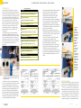
The electrical control panel with the two switches on the
left from which you control all the functions of this
combination machine.
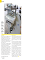
Captured by the desire to start up the machine and
test it as soon as possible, the assembly of the various
components might appear as annoyance, but we
think instead it is an excellent way to gain confidence
and start knowing the new machine.Having a foot
print of 1190 x 935 (without squaring frame and
morticer) the machine looks compact and well built.
The cast iron tables are well fixed and levelled with
each other and contribute to the solid look offered
by this small combined universal machine.
52
After having carefully cleaned the table tops from the
protective oil to avoid rusting and after having
installed a circular saw (we have opted for a
multifunction 60 tooth blade) we have carefully
looked at the electrical control panel. This is
positioned just below the circular saw setting handles
in an easy to reach position when using the saw blade
and spindle functions. For operations involving
planing, which are performed from the opposite side
of the machine, an emergency stop button is in close
proximity of the in feed table.
Returning to the main electrical control panel, it
incorporates a magneto-thermal two position switch, a
five position selector, the plug to connect the main
and an emergency button.
The use of the controls is intuitive; first select the
working group on the 5 position selector
(saw/planer/spindle/all off/unlock spindle brake)
then start the machine by selecting on the
thermo-magnetic switch position 1. The full stop of
all groups can be archived via the thermo-magnetic
switch or the two emergency buttons, the one
mounted on the front control panel being in an easily
accessible position during thickness operations, while
a bit more complicated while using the saw or the
spindle.
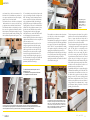
The blade tilts
through the
upper three
lobes knobs
group. The most
external moves
the blade, and
the coaxial
innermost locks
the position.
Given the
proximity to the
post that
supports the
cart, the
maneuvers are
not very easy
just as dial
reading.
The lower knob
instead controls
the rise/ fall of
the blade; it is
reachable more
easily but, given
its small
diameter, just
like the higher
one, requires a
certain effort
from the user to
be operated.
THE SAW GROUP
Positioned on the left side in respect of the control
panel, it shares the working table with the spindle and
allows for the use of a 250mm blade with 30mm bore.
The tool is protected by the extraction hood,
blocked with a lever above the riving knife. To Install
or substitute the blade it is necessary to remove the
access door placed on the left side and block the shaft
with the supplied pin. To remove or position the
saw blade on its shaft is not a effortless job as it
requires the pushing away of the extraction hood but,
n.24 year 2010
53