1
OUR TESTS
once learned, the up and down movements of the
blade and those for its inclination are performed via
one compass mechanism and one rack and pinion,
activated by two 3 faced rotary handle.
The diameter of these is a bit small to avoid reciprocal
interference hence it is necessary to be fairly strong
to spin them and move the blade in both directions.
The inclination reached can be checked by an index
that runs on the graduated arch behind the handle.
Like all solutions of this kind, the reading of the angle
value is affected by parallax, but the positioning of the
blade (verifiedin comparison to the stops at 45 ° and
90°) was absolutely correct, either by reference to the
wagon or by referring to the table on the right of the
blade. The carriage is made of aluminium extrusion
and runs on the rails of the frame (also alluminium)
using a polycarbonate ball slide. Not including the
pushing table, it measures 1140x200 mm and offers a
squaring capacity of 1300 mm. Can be blocked flush
with the strut via the guillotine movement of a plate,
pivoted on its mast, which links the two structures.
The squaring frame uses the classic flag support
which, when not in use, can be folded back on itself
to avoid hampering the movement around the
machine. The fixing of the frame to take a carriage is a
simple and functional device based on a steel plate on
which are screwed two rods.
The plate should be inserted in the side slot of the
carriage to support the inner side of the squaring
frame. On this are also two holes that hug the rod,
while the opposite side rests on the pin of the flag.
Externally the two slots, the chassis has two plastic
shoes that fit snugly inside the hollow side of the
carriage. Can be adjusted to align the upper edge of
the frame with that of the carriage. Once inserted the
shoes in the slot, tightening the two knobs links
permanently the frame to the carriage.
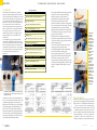
The tightening of the
squaring frame is via
the two knobs of the
support inserted in
the hollow of the
carriage.
The assembly does not take more than a few minutes
as it is fairly easy to do and can be accomplished
without the help a second person.
The installation of the squaring fence is as simple and
can be done on both sides of the frame perpendicular
to the wagon. The fence can be oriented between 90
and 45 ° and its 90 ° stops are adjustable. The locking
of the panels or work pieces on the carriage or on the
squaring frame is facilitated by the presence of a
mobile clamp that fits within the upper slot of the pre
buon a.The movement of the carriage is proceeding
smoothly and without jamming even with the
squaring frame installed, to the benefit of the finish of
the cut which is always good.
The blade tilt control revealed a perfect match of
the lines 45 and 90 °.
The visualization of the angular value is influenced
by the parallax and the size of the index.
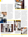
The wagon carriage, removed to highlight the sliding mechanism on the trellis, consists of a polycarbonate ball slide.
Two felts placed at the beginning and the end of the slide keeps the balls clean. The mobile guide located on the inner side of
the truss is registered at the factory to provide a movement of the carriage properly parallel to the blade.
54
The last component to be analyzed is the guide for
parallel cuts; also made from extruded aluminium, it
slips on a support that slides and locks, with an
eccentric lever, on a 'rod with a rectangular section
fixed to the cast iron surface of the machine.
The rod incorporates a line graph whose values can be
read through an open window on the support of the
guide. The line graph is not adjustable, but the
fastening of the rod to the surface allows its
adjustment to serve as a micro setting. The guide is
also used for working the planer and is therefore
longer than necessary when used on the saw. The end
opposite the point of locking on the support is
influenced by this factor and the elasticity of the guide
itself, when the guide is resting entirely on the surface,
and tends to move under pressure, but this is not a
problem because the guide can be moved
longitudinally with respect to its support, allowing the
withdrawal when machining closer to the blade. The
saw unit includes dust extraction on two fronts, over
the blade with the guard and under the machine
through an outlet. The system is well-thought and
allows almost complete extraction of dust. To test the
machine on the parallel cuts we have used blocks of
varying thickness, the combination blade / engine
proved adequate, leaving a finish free of burns and
generally good on all surfaces.
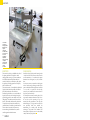
The parallel fence splits its functionality between the saw
and planer; when using with the saw it offers the lowest
stroke. On it, is locked a metal protection that serves to
cover the drum of the planer when it is not used at full
width. In the right picture, the window on the graphed line
allows you to set the distance from the blade.
n.24 year 2010
55