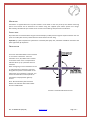
1
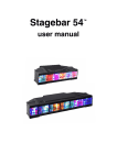
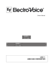
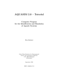
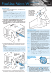
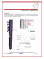
FUSION 672 - VIDEO BATTEN OVERVIEW The Fusion 672 Video Batten is a medium resolution video product. This 15mm pitch unit features tri-colour, surface mount LEDs, offers an ultra wide viewing angle and forms part of an entirely programmable system offering the user flexibility, adaptability and visual punch. F IGURE 1: A T YPICAL F USION S YSTEM F EATURING A F USION 672 V IDEO B ATTEN Doc: 07-000001-00 (May-09) www.illieum.com Page 1 of 7 QUICK START GUIDE A Fusion system can be assembled quickly, easily and can be up and running in a matter of minutes. The diagram in the Overview shows all possible configurations on a single diagram. This Quick Start Guide will help you identify which components you require and guide you through the setup process. 1. Mount your Fusion Fixtures. Refer to the Mounting section for details on mounting points, available brackets and safety points. 2. Connect data to the fixtures by creating a daisy chain including all fixtures. Refer to Data Cabling for further details. Connect the first Fusion fixture to the V-NET 0 (MAIN) connection on the Fusion Mapper. 3. Connect power to all the fixtures. Power can also be daisy chained. However, there is a limit to how many units can be connected in a single chain and depends on the fixtures used. Refer to the Power Cabling section for details of how many units can be connected in a single power chain. 4. Having connected power to the Fusion Mapper turn Autonumbering ON. DMX OPERATION For Art-net operation goto step 8. For full video operation goto step 11. 5. Connect the lighting desk or other DMX source to the DMX-1 IN port on the rear of the Fusion Mapper. 6. On the Fusion Mapper set the input source to ArtDmx and configure the Fusion 672 Video Battens via the fixture patching menu. 7. When you are happy with the setup turn Autonumbering OFF. You are now ready to go. All configured fixtures can now be controlled directly from the lighting desk. ART-NET OPERATION 8. Art-net operation requires the Fusion Mapper to be connected to a network via its NETWORK port. Configure the IP address and subnet mask to ensure the Fusion Mapper is properly connected to the network. 9. On the Fusion Mapper set the input source to ArtDmx and configure the Fusion 672 Video Battens via the fixture patching menu. 10. When you are happy with the setup turn Autonumbering OFF. You are now ready to go. All configured fixtures can now be controlled directly from the lighting desk. Doc: 07-000001-00 (May-09) www.illieum.com Page 2 of 7 FULL VIDEO OPERATION 11. Connect a DVI-D monitor to the Fusion Mapper along with a media server or other video source. 12. On the Fusion Mapper set the input source to DVI or VGA as appropriate to the video source. Adjust the crop area so that it envelops the area of the video to be displayed on the Fusion fixtures and configure the Fusion fixtures via the fixture patching menu. 13. When you are happy with the setup turn Autonumbering OFF. You are now ready to go. All configured fixtures will display the appropriate portion of the video feed. TROUBLESHOOTING No output on Fusion Fixtures: On the Fusion Mapper, check fixture blackout is OFF Check that each Fusion Fixture is mapped to a location within the crop area Check the video input to the Fusion Mapper and the input settings Check the power and input fuses Check indicators are illuminated on Fusion Fixtures and that no error is indicated No communication between Fusion Mapper and Fusion Fixtures Ensure connections between any two points in the system are connected directly using cat5e cable Ensure no hubs, switches or routers are use when connecting Fusion Fixtures together. All fixtures must be connected directly to the next fixture or Fusion Mapper No communication between Fusion Mapper and configuration computer of Art-net source: Check network connection and IP addresses of both Fusion Mapper and computer If the Fusion Mapper is connected directly to a computer ensure a crossover cable is used Check firewall settings on computer ensuring port 6455 is open Doc: 07-000001-00 (May-09) www.illieum.com Page 3 of 7 CONTENTS History page.......................................................................................................................................................... 1 Overview .............................................................................................................................................................. 1 Quick Start Guide .................................................................................................................................................. 2 DMX Operation ................................................................................................................................................. 2 Art-net Operation ............................................................................................................................................. 2 Full Video Operation ......................................................................................................................................... 3 Troubleshooting................................................................................................................................................ 3 Mounting .......................................................................................................................................................... 5 Safety wire........................................................................................................................................................ 5 Orientation ....................................................................................................................................................... 5 Data Cabling ..................................................................................................................................................... 6 Standby Connection .......................................................................................................................................... 6 Power Cabling................................................................................................................................................... 6 Specification ......................................................................................................................................................... 7 Physical............................................................................................................................................................. 7 Connections...................................................................................................................................................... 7 Environmental .................................................................................................................................................. 7 Electrical ........................................................................................................................................................... 7 Optical .............................................................................................................................................................. 7 Safety ............................................................................................................................................................... 7 Appendix A: Art-net and DMX modes .................................................................................................................... 1 Figure 1: A Typical Fusion System Featuring a Fusion 672 Video Batten.................................................................. 1 Figure 2: Fusion 672 Orientation ........................................................................................................................... 5 Doc: 07-000001-00 (May-09) www.illieum.com Page 4 of 7 MOUNTING Each batten is supplied with two ‘Top-Hat’ brackets. These attach to the rear panel top and bottom mounting points. Each bracket can be attached to the batten using the supplied quick release quarter turn fixings. Alternatively, two M5 bolts per bracket can be used for custom fittings and permanent installations. SAFETY WIRE Any batten that is mounted above the ground should employ a safety wire through the eyelet located on the rear panel. This safety wire and any related cleat should be rated to at least 15kg. Important: If a fixture experiences a fall that is arrested by the safety wire, the batten should be returned to the point of purchase for inspection ORIENTATION The Fusion 672 Video Batten can be mounted in one of four orientations. These are referred to as 0°, 90°, 180° & 270°. Located on the back of the unit is a compass which indicates which ay up a particular fixture is mounted. When configuring a Fusion 672 batten for use in video mode this orientation is required. Along with the position of the batten in the video space, the orientation is required. This ensures that the video content specific to each batten is displayed the right way around. Note: The orientation of the Fusion 672 batten is not relevant when used in either Art-net or DMX modes. F IGURE 2: F USION 672 O RIENTATION Doc: 07-000001-00 (May-09) www.illieum.com Page 5 of 7 DATA CABLING Fusion systems employ standard Cat 5e or Cat 6 network cable terminated with RJ45 connectors. For higher security Neutrik EtherCon® shells (NE8MC) should be used. These attach around standard cables already terminated with RJ45 connectors. The maximum length of each data cable is 100 meters. There is no minimum length. Important: Fusion 672 battens will not work if any data connection in the system is connected through a standard network hub, switch or router. 1) Connect the data feed from the Fusion Mapper ‘V PORT 0’ connector to port A on the first Fusion 672 batten. 2) Daisy-chain all the battens in the system. Connect port B to port A on the next batten, and so on. 3) Connect port B on the last batten back to the Fusion Mapper. Note: this connection is optional. See the Standby Connection section below. STANDBY CONNECTION Connect port B from the last batten back to the Fusion Mapper V PORT 1 connector. This protects the system against cable faults. In the event of a cable failing this protection link ensures the system continues to function without the loss of any part of the display image. POWER CABLING Power is fed to each Fusion 672 fixture using industry standard Neutrik PowerCon connectors (NAC3FCA and NAC3FCB). Battens can be daisy-chained providing no more than 20 units per feed are connected together. CONFIGURATION Fusion 672 Video Battens must be used in a system with a Fusion mapper. It is from this unit that the system is controlled and configured. Whether the Fusion 672’s are to be used in DMX, Art-net or video modes is all specified from the Fusion Mapper. For full details on how to setup and control the Fusion 672 batten from the Fusion Mapper refer to the Fusion Mapper User Manual. See Illieum.com and look for Fusion Extras. Doc: 07-000001-00 (May-09) www.illieum.com Page 6 of 7 SPECIFICATION PHYSICAL Length: Width: Maximum depth: Weight: 1080mm 90mm 60.2mm 3.3kg CONNECTIONS AC power In: AC power Out: Data: ENVIRONMENTAL Neutrik PowerCon® Neutrik PowerCon® 2 x Neutrik EtherCon® ELECTRICAL Input voltage: Power consumption: Fuse size: Fuse rating: Max. ambient temperature: IP rating: 40°C IP44 OPTICAL 90 to 264V AC, 47 to 63Hz 100W (max.) 20 x 5mm 3.15A (slow) 250VAC Min. luminous intensity: Colour processing: Viewing angle: 910mcd/pixel (full white) 16-bit 165° SAFETY EU: EN60950-1 2006/95/EC – The Low Voltage Directive 2004/108/EC – The EMC Directive Doc: 07-000001-00 (May-09) www.illieum.com Page 7 of 7 APPENDIX A: ART-NET AND DMX MODES Chan. 1 2 3 4 5 6 7 8 9 10 11 12 13 14 15 16 17 18 19 20 21 22 23 24 25 26 27 28 29 30 31 32 33 34 35 36 37 38 39 40 41 42 43 0:36RGB Red (cell 1) Grn. (cell 1) Blue (cell 1) Red (cell 2) Grn. (cell 2) Blue (cell 2) Red (cell 3) Grn. (cell 3) Blue (cell 3) Red (cell 4) Grn. (cell 4) Blue (cell 4) Red (cell 5) Grn. (cell 5) Blue (cell 5) Red (cell 6) Grn. (cell 6) Blue (cell 6) Red (cell 7) Grn. (cell 7) Blue (cell 7) Red (cell 8) Grn. (cell 8) Blue (cell 8) Red (cell 9) Grn. (cell 9) Blue (cell 9) Red (cell 10) Grn. (cell 10) Blue (cell 10) Red (cell 11) Grn. (cell 11) Blue (cell 11) Red (cell 12) Grn. (cell 12) Blue (cell 12) - 1:36RGB+I Red (cell 1) Grn. (cell 1) Blue (cell 1) Red (cell 2) Grn. (cell 2) Blue (cell 2) Red (cell 3) Grn. (cell 3) Blue (cell 3) Red (cell 4) Grn. (cell 4) Blue (cell 4) Red (cell 5) Grn. (cell 5) Blue (cell 5) Red (cell 6) Grn. (cell 6) Blue (cell 6) Red (cell 7) Grn. (cell 7) Blue (cell 7) Red (cell 8) Grn. (cell 8) Blue (cell 8) Red (cell 9) Grn. (cell 9) Blue (cell 9) Red (cell 10) Grn. (cell 10) Blue (cell 10) Red (cell 11) Grn. (cell 11) Blue (cell 11) Red (cell 12) Grn. (cell 12) Blue (cell 12) Master int. - Doc: 07-000001-00 (May-09) 2:18RGB Red (cell 1) Grn. (cell 1) Blue (cell 1) Red (cell 2) Grn. (cell 2) Blue (cell 2) Red (cell 3) Grn. (cell 3) Blue (cell 3) Red (cell 4) Grn. (cell 4) Blue (cell 4) Red (cell 5) Grn. (cell 5) Blue (cell 5) Red (cell 6) Grn. (cell 6) Blue (cell 6) - 3:18RGB+I Red (cell 1) Grn. (cell 1) Blue (cell 1) Red (cell 2) Grn. (cell 2) Blue (cell 2) Red (cell 3) Grn. (cell 3) Blue (cell 3) Red (cell 4) Grn. (cell 4) Blue (cell 4) Red (cell 5) Grn. (cell 5) Blue (cell 5) Red (cell 6) Grn. (cell 6) Blue (cell 6) Master int. - 4:12RGB Red (cell 1) Grn. (cell 1) Blue (cell 1) Red (cell 2) Grn. (cell 2) Blue (cell 2) Red (cell 3) Grn. (cell 3) Blue (cell 3) Red (cell 4) Grn. (cell 4) Blue (cell 4) - 5:12RGB+I Red (cell 1) Grn. (cell 1) Blue (cell 1) Red (cell 2) Grn. (cell 2) Blue (cell 2) Red (cell 3) Grn. (cell 3) Blue (cell 3) Red (cell 4) Grn. (cell 4) Blue (cell 4) Master int. - 6:9RGB Red (cell 1) Grn. (cell 1) Blue (cell 1) Red (cell 2) Grn. (cell 2) Blue (cell 2) Red (cell 3) Grn. (cell 3) Blue (cell 3) - 7:9RGB+I Red (cell 1) Grn. (cell 1) Blue (cell 1) Red (cell 2) Grn. (cell 2) Blue (cell 2) Red (cell 3) Grn. (cell 3) Blue (cell 3) Master int. - www.illieum.com 8:6RGB Red (cell 1) Grn. (cell 1) Blue (cell 1) Red (cell 2) Grn. (cell 2) Blue (cell 2) - 9:6RGB+I Red (cell 1) Grn. (cell 1) Blue (cell 1) Red (cell 2) Grn. (cell 2) Blue (cell 2) Master int. - 10:3RGB Red Grn. Blue - 11:3RGB+I Red Grn. Blue Master int. - 12:6FX+I C1 Effect C1 Speed C1 Xfade C2 Effect C2 Speed C2 Xfade Master int. - 13:3RGB6FXI Red Grn. Blue C1 Effect C1 Speed C1 Xfade C2 Effect C2 Speed C2 Xfade Master int. - 14:36RGB6FXI Red (cell 1) Grn. (cell 1) Blue (cell 1) Red (cell 2) Grn. (cell 2) Blue (cell 2) Red (cell 3) Grn. (cell 3) Blue (cell 3) Red (cell 4) Grn. (cell 4) Blue (cell 4) Red (cell 5) Grn. (cell 5) Blue (cell 5) Red (cell 6) Grn. (cell 6) Blue (cell 6) Red (cell 7) Grn. (cell 7) Blue (cell 7) Red (cell 8) Grn. (cell 8) Blue (cell 8) Red (cell 9) Grn. (cell 9) Blue (cell 9) Red (cell 10) Grn. (cell 10) Blue (cell 10) Red (cell 11) Grn. (cell 11) Blue (cell 11) Red (cell 12) Grn. (cell 12) Blue (cell 12) C1 Effect C1 Speed C1 Xfade C2 Effect C2 Speed C2 Xfade Master int.