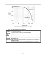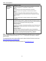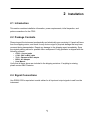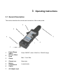
1
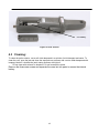
Model: CP62
DC – 100 A Current Probe
USER MANUAL
1
Safety Summary
The following safety precautions apply to both operating and maintenance personnel and must be
observed during all phases of operation, service, and repair of this instrument. Before applying
power, follow the installation instructions and become familiar with the operating instructions for this
instrument.
If this device is damaged or something is missing, contact the place of purchase immediately.
This manual contains information and warnings that must be followed to ensure safe operation as
well as maintain the meter in a safe condition.
GROUND THE INSTRUMENT
To minimize shock hazard, the instrument chassis and cabinet must be connected to an electrical
ground. This instrument is grounded through the ground conductor of the supplied, three-conductor
ac power cable. The power cable must be plugged into an approved three-conductor electrical
outlet. Do not alter the ground connection. Without the protective ground connection, all accessible
conductive parts (including control knobs) can render an electric shock. The power jack and mating
plug of the power cable must meet IEC safety standards.
DO NOT OPERATE IN AN EXPLOSIVE ATMOSPHERE
Do not operate the instrument in the presence of flammable gases or fumes. Operation of any
electrical instrument in such an environment constitutes a definite safety hazard.
KEEP AWAY FROM LIVE CIRCUITS
Instrument covers must not be removed by operating personnel. Component replacement and
internal adjustments must be made by qualified maintenance personnel. Disconnect the power
cord before removing the instrument covers and replacing components. Under certain conditions,
even with the power cable removed, dangerous voltages may exist. To avoid injuries, always
disconnect power and discharge circuits before touching them.
DO NOT SERVICE OR ADJUST ALONE
Do not attempt any internal service or adjustment unless another person, capable of rendering first
aid and resuscitation, is present.
DO NOT SUBSTITUTE PARTS OR MODIFY THE INSTRUMENT
Do not install substitute parts or perform any unauthorized modifications to this instrument. Return
the instrument to B&K Precision for service and repair to ensure that safety features are maintained.
WARNINGS AND CAUTIONS
WARNING and CAUTION statements, such as the following examples, denote a hazard and
appear throughout this manual. Follow all instructions contained in these statements.
A WARNING statement calls attention to an operating procedure, practice, or condition, which, if
not followed correctly, could result in injury or death to personnel.
A CAUTION statement calls attention to an operating procedure, practice, or condition, which, if not
followed correctly, could result in damage to or destruction of part or all of the product.
WARNING:
Do not alter the ground connection. Without the protective ground connection, all accessible
conductive parts (including control knobs) can render an electric shock. The power jack and mating
plug of the power cable meet IEC safety standards.
WARNING:
To avoid electrical shock hazard, disconnect power cord before removing covers. Refer servicing to
qualified personnel.
CAUTION:
Before connecting the line cord to the AC mains, check the rear panel AC line voltage indicator.
Applying a line voltage other than the indicated voltage can destroy the AC line fuses. For continued
fire protection, replace fuses only with those of the specified voltage and current ratings.
2
CAUTION:
This product uses components which can be damaged by electro-static discharge (ESD). To avoid
damage, be sure to follow proper procedures for handling, storing and transporting parts and
subassemblies which contain ESD-sensitive components.
Compliance Statements
Disposal of Old Electrical & Electronic Equipment (Applicable in the European
Union and other European countries with separate collection systems)
This product is subject to Directive 2002/96/EC of the
European
Parliament and the Council of the European Union on
waste
electrical and electronic equipment (WEEE) , and in
jurisdictions
adopting that Directive, is marked as being put on the
market after August 13, 2005, and should not be
disposed of as unsorted
municipal waste. Please utilize your local WEEE
collection
facilities in the disposition of this product and
otherwise observe all applicable requirements.
Safety Symbols
! Terms in This Manual. These terms may appear in this manual:
WARNING. Warning statements identify conditions or practices that could result in
injury or loss of life.
CAUTION. Caution statements identify conditions or practices that could result in
damage to this product or other property.
! Terms on the Product. These terms may appear on the product:
DANGER indicates an injury hazard immediately accessible as you read the marking.
WARNING indicates an injury hazard not immediately accessible as you read the marking.
CAUTION indicates a hazard to property including the product.
! Symbols on the Product. These symbols may appear on the product:
Attention refer to operation Instructions.
This instrument has double insulation.
3
CE Declaration of Conformity
The model CP62 meets the requirements of 2006/95/EC Low Voltage Directive and
2004/108/EC Electromagnetic Compatibility Directive with the following standards.
Low Voltage Directive
-
EN61010
Safety requirements for electrical equipment for measurement, control,
and laboratory use.
EMC Directive
-
EN55011
For radiated and conducted emissions.
EN55082
Electrical discharge immunity
4
1 INTRODUCTION ................................................................. 6 1.1 Introduction .............................................................................................. 6 1.2 Description ............................................................................................... 6 1.3 Specifications ........................................................................................... 6 Table 1.3.0
Table 1.3.1
Table 1.3.2
Table 1.3.3
Table 1.3.4
Table 1.3.5
2 Electrical Characteristics ................................................................. 6 Voltage and current ratings ............................................................. 6 Physical Characteristics .................................................................. 7 Environmental Characteristics ........................................................ 7 Power Requirements ..................................................................... 7 Certifications and compliances ....................................................... 9 INSTALLATION ................................................................ 11 2.1 Introduction ............................................................................................ 11 2.2 Package Contents .................................................................................. 11 2.4 Signal Connections ................................................................................ 11 3 OPERATING INSTRUCTIONS ......................................... 12 3.1
3.2
3.3
3.4
General Description ............................................................................... 12 Controls and Indicators .......................................................................... 13 Connectors ............................................................................................. 13 Oscilloscope Measurements .................................................................. 14 3.4.2 Multimeter Measurements ...................................................................... 15 3.4.3 Increase Sensitivity ................................................................................ 15 4 MAINTENANCE ................................................................ 16 4.1 Battery and AC Power Adapter Operation: ........................................... 16 4.2 Battery Installation: ................................................................................ 16 4.3 Cleaning: ............................................................................................... 17
5
1
CP62 – Operating Manual
1
Introduction
1.1 Introduction
This manual contains information required to operate the B&K Precision model CP62 Current
Probe. This section covers the instrument’s general description, specifications and
characteristics.
1.2 Description
The CP62 current probe allows a general purpose oscilloscope to display AC and DC current signals
up to 100 A Peak (70 A RMS). The CP62 current probe can also make AC and DC measurements
with a multimeter by using the recommended accessory TL62 (BNC-to-banana) plug adapter.
1.3 Specifications
Table 1.3.0 Electrical Characteristics
Current Ranges
10/100 mV/A
DC Accuracy, typical
±3% ±50 mA at 100 mV/A
(50 mA to 10 A peak range)
±4% ±50 mA at 10 mV/A
(500 mA to 40 A peak range)
±15% max at 100 mV/A
(40 A peak to 100 A peak range)
Table 1.3.1 Voltage and current ratings
Maximum working current (A)
Maximum
Working voltage
(V)
Maximum floating
voltage (V)
Rating
Range
10 mV/A
Range
100 mV/A
DC
100 *
10
600
600
*
10
600
600
DC + peak AC
100
AC peak
100
10
600
600
AC peak-peak
200
20
1200
-
RMS CAT III
70.7
7.07
300
300
RMS CAT II
70.7
7.07
600
600
RMS CAT I
70.7
7.07
600
600
*See Figure 2 for frequency derating.
6
Table 1.3.2 Physical Characteristics
Dimensions
280 mm x 70mm x 32 mm
(11 x 2.8 x 1.3 inch)
Maximum Conductor Size
11 mm (0.43 inch)
Cable Length
100 cm ( 3.3 feet)
Weight
260 g (9.5 oz) (without battery)
Table 1.3.3 Environmental Characteristics
Temperature
Working
Storage
0°C to +50°C (+32°F to +122°F)
-20°C to +80°C (-4°F to +176°F)
Humidity
0°C to 40°C, 95% humidity
40°C to 50°C, 45% humidity
Pollution Degree
2
Table 1.3.4
Power Requirements
Battery
9V NEDA 1604A, IEC 6LR61
AC Adapter
Linear AC adapter with 9VDC, 300mA, and center
negative output
Figure 1: Gain versus frequency at 1 A peak, typical
7
1
CP62 – Operating Manual
Figure 2: Maximum current versus frequency
Figure 3: DC signal linearity in the 10 mV/A range, typical
8
Figure 4: Phase versus frequency at 1 A peak, typical
Table 1.3.5 Certifications and compliances
EC
Declaration
of
Conformity
– Low
Voltage
Compliance was demonstrated to the following specification as listed in the Official
Journal of the European Union:
Additional
Compliance
IEC61010-1/A2:1995
Safety requirements for electrical equipment for measurement, control, & laboratory use.
IEC61010-2-032:1994
Particular requirements for hand-held current clamps for electrical test & measurement.
Low Voltage Directive 73/23/EEC, as amended by 93/68/EEC
EN 61010-1/A2:1995
Safety requirements for electrical equipment for measurement, control, & laboratory use.
EN 61010-2-032:1995
Particular requirements for hand-held current clamps for electrical test & measurement.
9
1
CP62 – Operating Manual
Certifications and compliances (cont.)
Installation
Terminals on this product may have different installation (overvoltage)
(Overvoltage)
category designations. The installation categories are:
Category
CAT III
Distribution-level mains (usually permanently connected).
Equipment at this level is typically in a fixed industrial location.
CAT II
Local-level mains (wall sockets). Equipment at this level includes
appliances, portable tools, and similar products. Equipment is usually
cord-connected.
CAT I
Secondary (signal level) or battery operated circuits of electronic
equipment.
Pollution Degree
A measure of the contaminates that could occur in the environment
around and within a product. Typically the internal environment inside a
product is considered to be the same as the external. Products should be
used only in the environment for which they are rated.
Pollution Degree 1
No pollution or only dry, nonconductive pollution occurs. Products in this
category are generally encapsulated, hermetically sealed, or located in
clean rooms.
Pollution Degree 2
Normally only dry, nonconductive pollution occurs. Occasionally a
temporary conductivity that is caused by condensation must be expected.
This location is a typical office/home environment. Temporary
condensation occurs only when the product is out of service.
Note: All specifications apply to the unit after a temperature stabilization time of 15 minutes
over an ambient temperature range of 23 °C ± 5 °C. Specifications are subject to change
without notice.
To ensure the most current version of this manual, please download the latest version here:
http://www.bkprecision.com/search/CP62
For current up-to-date product information, please visit www.bkprecision.com
10
2 Installation
2.1 Introduction
This section contains installation information, power requirements, initial inspection, and
probe connections for the CP62.
2.2 Package Contents
Please inspect the instrument mechanically and electrically upon receiving it. Unpack all items
from the shipping carton, and check for any obvious signs of physical damage that may have
occurred during transportation. Report any damage to the shipping agent immediately. Save
the original packing carton for possible future reshipment. Every generator is shipped with the
following contents:
•
•
•
•
•
CP62 – Current probe
CC62 - BNC to BNC cable
TL62 – Banana to BNC adapter
BE62 - AC Adapter
User Manual
Verify that all items above are included in the shipping container. If anything is missing,
please contact B&K Precision.
2.4 Signal Connections
Use RG58U 50Ω or equivalent coaxial cables for all input and output signals to and from the
instrument.
11
1
3 Operating Instructions
3.1 General Description
This section describes the controls and connectors of the current probe.
4
5
3
6
1
2
7
1
2
Power/ Range
Switch
DC Zero Offset
Knob
3
Clamp
4
6
Clamp Lever
Battery
Compartment
Output
7
AC Adapter Input
5
Power ON/OFF, select 10mV/A or 100mV/A range
Max. 11 mm Wire
Opens jaw
Located inside
3.2 Controls and Indicators
Control/Indicator
Description
Current flow symbol. The arrow shows the probe’s
polarity convention for measuring current flowing
from positive to negative.
Zero adjustment. Rotate to adjust the probe output
to zero when there is no current present. It may also
be used to offset a DC signal component. Zeroing is
not needed for AC measurements unless your
instrument cannot isolate a DC component (if
present).
OFF/Range switch. Slide the switch from OFF to
either the 10 mV/A or 100mV/A range. When either
range is selected, the probe is turned on, and the
green battery indicator lights. If the indicator does not
light, see Battery Notes and Battery Installation on
page16.
Battery indicator. The green battery indicator lights
when the probe is turned on. For more information,
see Battery Notes and Battery Installation on
page16.
Overload indicator. The red overload indicator
lights if the measured signal is greater than the
selected range capacity. Switch the probe to 10
mV/A if possible, or remove the probe from the
circuit.
3.3 Connectors
The CP62 has one BNC connector and one AC input.
BNC Output
Use this connector to transfer the induced signals to either an oscilloscope or to a digital multimeter.
Input
Use this connector to power the probe via BE62 AC adapter.
13
CP62 – Operating Manual
3.4 Oscilloscope Measurements
Before using the probe, the batteries or specified power adapter must be installed. See the battery
installation instructions on page 16.
WARNING!
Do not clamp the probe onto circuits with voltages greater than 600 VAC. Personal injury or
damage to the probe may result.
Always connect the CP62 current probe output to the instrument before clamping onto the
circuit under test.
1. First connect the current probe BNC connector to CC62 (double BNC connection cable) then
connect to oscilloscope input. Start by setting the oscilloscope voltage input channel to DC volts, and
the voltage sensitivity scale to 0.1 V/div.
2. Move the OFF/ Range switch to the 10 mV/A or 100 mV/A position to turn on the probe.
(*The CP62 current probe has a green LED power/battery indicator. If the LED does not light, replace
the battery or use specified power adapter.)
3. Use the ZERO adjustment to zero or offset the probe output detection of residual magnetic DC
charges.
4. Connect the probe to the circuit by opening the jaws and clamping around the conductor.
See Figure 5.
NOTE. Clamping around both the “hot” and neutral wires may give you a zero reading.
(Remember to unclamp the probe from the conductor before disconnecting it from your
meter or instrument).
Figure 5: Connecting the CP62 current probe.
5. Adjust the oscilloscope’s time base as necessary to get a clear and stable view of the signal. Set
the oscilloscope input to DC volts to see both the AC and DC currents, or set the input to AC to see
the AC current only. Figure 6 shows the difference between the line current drawn by a resistive load
and a motor controller.
14
Figure 6: Typical current waveforms
3.4.2 Multimeter Measurements
When connecting to a digital meter, use the recommended TL62 (BNC-to-banana adapter). Connect
the black lead to the meter COM (black letters on the meter), and the red lead to the VΩ input (red
letters on the meter).
To measure only AC current, set the meter to measure AC volts.
To measure DC current, set the meter to measure DC volts. Note the current convention arrow on the
probe to get the proper polarity reading.
3.4.3
Increase Sensitivity
To increase the measurement sensitivity of the CP62 current probe, loop additional turns of the wire
under test through the jaws. See Figure 7. The sensitivity of the CP62 current probe is multiplied times
the number of loops in the jaws. For example: 10 mV/A X 4 turns = 40 mV/A.
Figure 7: Increasing the sensitivity
15
CP62 – Operating Manual
4 Maintenance
Use the information in this section to properly maintain the operation of your CP62 AC/DC Current
Probe.
4.1 Battery and AC Power Adapter Operation:
The CP62 current probe uses a single 9 V battery. Only use alkaline batteries.
As the battery in the CP62 current probe is drained, significant gain errors may occur. The green LED
will continue to light until a low battery voltage of 6.5 V is reached. If probe gain errors are detected
before the LED extinguishes or becomes dim, replace the probes battery with a fresh one.
Alternatively, an AC power adapter can be used to avoid gain error due to the battery condition. Switch
to a square 9V battery only when there is no AC power supply available outdoors.
When using an AC power adapter for an extended time, we suggest you remove the battery from the
compartment. This is because overheating may cause battery leakage, which may damage circuitry.
It is safe to power the CP62 with the AC adapter while the battery is installed. Disconnecting the
external power supply will not produce waveform anomaly or any damage. However, when operating
the CP62 with the AC adapter for an extended time period (more than 1 week), removal of the battery is
recommended, to avoid battery leakage.
4.2 Battery Installation:
(1) Remove the probe from the circuit.
(2) Open the battery compartment by loosening screws and take the cover off. Install/replace the
battery.
(3) While observing polarity, attach the new alkaline battery to the battery connectors and insert battery
(4) Place the cover back and lightly tighten the screws to hold the cover in place.
9V Battery
Figure 8: Pre 2014 version
16
9V Battery
Figure 9: 2014 version
4.3 Cleaning:
To clean the probe exterior, use a soft cloth dampened in a solution of mild detergent and water. To
clean the core, open the jaw and clean the exposed core surfaces with a cotton swab dampened with
isopropyl alcohol. Lubricate the jaws’ mating surfaces with light oil.
Do not clean with solvents or abrasives. Do not immerse the probe.
Remove the three case screws and separate the case into two parts to access the internal
battery.
17
CP62 – Operating Manual
SERVICE INFORMATION
Warranty Service: Please go to the support and service section on our website at www.bkprecision.com to obtain an RMA #.
Return the product in the original packaging with proof of purchase to the address below. Clearly state on the RMA the
performance problem and return any leads, probes, connectors and accessories that you are using with the device.
Non-Warranty Service: Please go to the support and service section on our website at www.bkprecision.com to obtain an
RMA #. Return the product in the original packaging to the address below. Clearly state on the RMA the performance problem
and return any leads, probes, connectors and accessories that you are using with the device. Customers not on an open
account must include payment in the form of a money order or credit card. For the most current repair charges, please refer to
the service and support section on our website.
Return all merchandise to B&K Precision Corp. with pre-paid shipping. The flat-rate repair charge for Non-Warranty Service
does not include return shipping. Return shipping to locations in North America is included for Warranty Service. For overnight
shipments and non-North American shipping fees please contact B&K Precision Corp.
B&K Precision Corp.
22820 Savi Ranch Parkway
Yorba Linda, CA 92887
www.bkprecision.com
714-921-9095
Include with the returned instrument your complete return shipping address, contact name, phone number and
description of problem.
LIMITED ONE-YEAR WARRANTY
B&K Precision Corp. warrants to the original purchaser that its products and the component parts thereof, will be free from
defects in workmanship and materials for a period of one year from date of purchase.
B&K Precision Corp. will, without charge, repair or replace, at its option, defective product or component parts. Returned
product must be accompanied by proof of the purchase date in the form of a sales receipt.
To help us better serve you, please complete the warranty registration for your new instrument via our website
www.bkprecision.com
Exclusions: This warranty does not apply in the event of misuse or abuse of the product or as a result of
unauthorized alterations or repairs. The warranty is void if the serial number is altered, defaced or removed.
B&K Precision Corp. shall not be liable for any consequential damages, including without limitation damages resulting from
loss of use. Some states do not allow limitations of incidental or consequential damages. So the above limitation or exclusion
may not apply to you.
This warranty gives you specific rights and you may have other rights, which vary from state-to-state.
B&K Precision Corp.
22820 Savi Ranch Parkway
Yorba Linda, CA 92887
www.bkprecision.com
714-921-9095
18
22820 Savi Ranch Parkway
Yorba Linda, CA 92887
www.bkprecision.com
© 2014 B&K Precision Corp.
v063014
Mouser Electronics
Authorized Distributor
Click to View Pricing, Inventory, Delivery & Lifecycle Information:
B&K Precision:
CP62