1
MODEL 4045
20MHz DDS Sweep Function Generator with Arb Function
OPERATING MANUAL
V021114
1
Model 4045 – Operating Manual
V092711
Limited Three-Year Warranty
B&K Precision warrants to the original purchaser that its products and the component parts
thereof, will be free from defects in workmanship and materials for a period of three years from
date of purchase from an authorized B&K Precision distributor.
B&K Precision will, without charge, repair or replace, at its option, defective product or
component parts. Returned product must be accompanied by proof of the purchase date in the
form of a sales receipt.
To obtain warranty coverage in the U.S.A., this product must be registered by completing the
warranty registration form on www.bkprecision.com within fifteen (15) days of purchase.
Exclusions: This warranty does not apply in the event of misuse or abuse of the product
or as a result of unauthorized alterations or repairs. The warranty is void if the serial
number is altered, defaced or removed.
B&K Precision shall not be liable for any consequential damages, including without limitation
damages resulting from loss of use. Some states do not allow limitations of incidental or
consequential damages. So the above limitation or exclusion may not apply to you.
This warranty gives you specific rights and you may have other rights, which vary from state-tostate.
Service Information
Warranty Service: Please return the product in the original packaging with proof of purchase to
the address below. Clearly state in writing the performance problem and return any leads,
probes, connectors and accessories that you are using with the device.
Non-Warranty Service: Return the product in the original packaging to the address below.
Clearly state in writing the performance problem and return any leads, probes, connectors and
accessories that you are using with the device. Customers not on open account must include
payment in the form of a money order or credit card. For the most current repair charges please
visit www.bkprecision.com and click on “service/repair”.
Return all merchandise to B&K Precision with pre-paid shipping. The flat-rate repair charge for
Non-Warranty Service does not include return shipping. Return shipping to locations in North
American is included for Warranty Service only. For overnight shipments and non-North
American shipping fees please contact B&K Precision.
B&K Precision
22820 Savi Ranch Parkway
Yorba Linda, CA 92887
www.bkprecision.com
714-921-9095
Include with the returned instrument your complete return shipping address, contact
name, phone number and description of problem.
2
Safety Summary
The following safety precautions apply to both operating and maintenance personnel and must be observed during
all phases of operation, service, and repair of this instrument. Before applying power, follow the installation
instructions and become familiar with the operating instructions for this instrument.
Failure to comply with these precautions or with specific warnings elsewhere in this manual violates safety
standards of design, manufacture, and intended use of the instrument. B&K PRECISION assumes no liability for a
customer’s failure to comply with these requirements. This is a Safety Class I instrument.
GROUND THE INSTRUMENT
To minimize shock hazard, the instrument chassis and cabinet must be connected to an electrical ground. This
instrument is grounded through the ground conductor of the supplied, three-conductor ac power cable. The power
cable must be plugged into an approved three-conductor electrical outlet. Do not alter the ground connection.
Without the protective ground connection, all accessible conductive parts (including control knobs) can render an
electric shock. The power jack and mating plug of the power cable meet IEC safety standards.
DO NOT OPERATE IN AN EXPLOSIVE ATMOSPHERE
Do not operate the instrument in the presence of flammable gases or fumes. Operation of any electrical instrument
in such an environment constitutes a definite safety hazard.
KEEP AWAY FROM LIVE CIRCUITS
Instrument covers must not be removed by operating personnel. Component replacement and internal adjustments
must be made by qualified maintenance personnel. Disconnect the power cord before removing the instrument
covers and replacing components. Under certain conditions, even with the power cable removed, dangerous
voltages may exist. To avoid injuries, always disconnect power and discharge circuits before touching them.
DO NOT SERVICE OR ADJUST ALONE
Do not attempt any internal service or adjustment unless another person, capable of rendering first aid and
resuscitation, is present.
DO NOT SUBSTITUTE PARTS OR MODIFY THE INSTRUMENT
Do not install substitute parts or perform any unauthorized modifications to this instrument. Return the instrument
to TEXIO for service and repair to ensure that safety features are maintained.
WARNINGS AND CAUTIONS
WARNING and CAUTION statements, such as the following examples, denote a hazard and appear throughout this
manual. Follow all instructions contained in these statements.
A WARNING statement calls attention to an operating procedure, practice, or condition, which, if not followed
correctly, could result in injury or death to personnel.
A CAUTION statement calls attention to an operating procedure, practice, or condition, which, if not followed
correctly, could result in damage to or destruction of part or all of the product.
3
Model 4045 – Operating Manual
WARNING:
This image cannot currently be displayed.
WARNING:
This image cannot currently be displayed.
CAUTION:
This image cannot currently be displayed.
CAUTION:
This image cannot currently be displayed.
Do not alter the ground connection. Without the protective ground connection, all
accessible conductive parts (including control knobs) can render an electric shock. The
power jack and mating plug of the power cable meet IEC safety standards.
To avoid electrical shock hazard, disconnect power cord before removing covers. Refer
servicing to qualified personnel.
Before connecting the line cord to the AC mains, check the rear panel AC line voltage
indicator. Applying a line voltage other than the indicated voltage can destroy the AC
line fuses. For continued fire protection, replace fuses only with those of the specified
voltage and current ratings.
This product uses components which can be damaged by electro-static discharge (ESD).
To avoid damage, be sure to follow proper procedures for handling, storing and
transporting parts and subassemblies which contain ESD-sensitive components.
4
Contents
Section 1
Section 2
Section 3
Section 4
Introduction
1.1
Introduction .............................................................................................................................
6
1.2
Description ..............................................................................................................................
6
1.3
Specifications ..........................................................................................................................
7
Installation
2.1
Introduction .............................................................................................................................
10
2.2
Mechanical inspection .............................................................................................................
10
2.4
Instrument mounting ...............................................................................................................
10
2.5
Power requirements .................................................................................................................
10
2.6
Grounding requirements ..........................................................................................................
11
2.7
Signal connections...................................................................................................................
11
2.8
USB Virtual COM ...................................................................................................................
11
Operating Instructions
3.1
General Description .................................................................................................................
12
3.2
Display Window ......................................................................................................................
13
3.3
Front Panel Controls ................................................................................................................
13
3.4
Connectors...............................................................................................................................
13
3.5
Output Connections .................................................................................................................
13
3.6
Menu Keys ..............................................................................................................................
14
3.7
ON Key ...................................................................................................................................
22
3.8
Cursor Movement Keys ...........................................................................................................
22
3.9
Rotary Input Knob ...................................................................................................................
22
3.10
Power-on Settings....................................................................................................................
23
3.11
Memory ...................................................................................................................................
23
3.12
Displaying Errors ....................................................................................................................
24
3.13
Using the Model 4045 .............................................................................................................
24
3.14
Examples .................................................................................................................................
25
Programming
4.1
Overview .................................................................................................................................
28
4.2
Device States ...........................................................................................................................
28
4.3
Message Exchange Protocol ....................................................................................................
28
4.4
Instrument Identification .........................................................................................................
29
4.5
Instrument Reset ......................................................................................................................
29
4.6
Command Syntax ....................................................................................................................
29
4.7
Status Reporting ......................................................................................................................
31
4.8
Common Commands ...............................................................................................................
34
4.9
Instrument Control Commands................................................................................................
35
4.10
Remote Programming ..............................................................................................................
50
5
Model 4045 – Operating Manual
Section 1
Introduction
1.1 Introduction
This manual contains information required to operate, program and test the Model 4045 - 20MHz DDS
Sweep Function Generator with Arb Function. This section covers the instrument general description,
instrument specifications and characteristics.
1.2 Description
The Model 4045 is a versatile high performance arbitrary waveform generator. Arbitrary waveforms can be
programmed and generated with 12 bit resolution and up to 1,000 points length. Waveforms can be output
in continuous, triggered, gated or burst mode. AM and FM modulation combined with versatile Sweep
capabilities make the unit suitable for a wide range of applications.
Editing is flexible and easy including auto increment, line draw and predefined waveform facilities. The
instrument can be remotely operated via the USB virtual COM serial interface bus and it is SCPI
compatible.
1.3 Memory Architecture
The waveform memory consists of 1,000 points. The user can edit arbitrary waveforms in waveform
memory and can specify any data value in the range from -2047 to 2047 for any point in waveform
memory.
The following operations can be performed in the waveform memory:
- Insert and scale any of the following predefined waveforms:
sine
triangle
square
ramp up
ramp down
noise
- Draw a line between any two points
- Clear (set to zero) any set of points or all points
- Set individual point values
Up to 1000 continuous points of waveform memory can be executed by specifying a starting address in
waveform memory and length.
After specifying a section of waveform memory for execution, the following parameters can be set:
- Point rate (frequency)
- Peak-to-peak amplitude
- Offset voltage
6
MODEL 4045 - SPECIFICATIONS
GENERAL DESCRIPTION
The Model 4045 is a programmable arbitrary waveform generator that can generate arbitrary waveforms and
predefined signal as: Sine, Triangle, Square, Pulse, etc.
FREQUENCY CHARACTERISTICS (STANDARD WAVEFORMS)
Sine
Square
Triangle , Ramp
Accuracy
Resolution
-
0.01 Hz to 20 MHz
0.01 Hz to 20 MHz
0.01 Hz to 2 MHz
0.005 % (50 ppm)
at <100 Hz = 0.005 % + 0.006 Hz
- 6 digits or 10 mHz
ARBITRARY CHARACTERISTICS
Waveform length
Vertical resolution
Sampling rate
Accuracy
Resolution
-
2 points to 1,000 points
12 bits
20ns to 50s
0.005 % (50 ppm)
4 digits
OUTPUT CHARACTERISTICS
Amplitude Range
Resolution
Amplitude Accuracy
Flatness
(for sine wave at 5Vpp into 50 Ω)
Offset Range
Offset Resolution
Offset Accuracy
Output Impedance
Output Protection
Filter
-
10mV to 10Vp-p into 50 ohms
3 digits (1000 counts)
± 2% ± 20mV of the programmed output from 1.01V- 10V
0.5 dB at 1MHz
1 dB to 20 MHz
± 4.5V into 50 ohms, depending on the Amplitude setting
10 mV with 3 digits resolution
± 2% ± 10mV into 50 ohms
50 ohms
The instrument output is protected against short circuit or accidental
voltage practically available in electronic laboratories, applied to the
main output connector
- 9 pole Elliptic
WAVEFORM CHARACTERISTICS
Harmonic Distortion
(for sine wave at 5Vpp into 50 Ω)
Spurious
Square Rise/Fall Time
-
DC-20 KHz
-55 dBc
20 KHz-100 KHz
-50 dBc
100 KHz-1 MHz
-40 dBc
1 MHz-20 MHz
-30 dBc
DC-1MHz
<-60 dBc
< 18 ns (10% to 90%) at full amplitude into 50 ohms
7
Model 4045 – Operating Manual
Variable Duty Cycle
Symmetry at 50%
OPERATING MODES
- 20% to 80% to 2 MHz for Square and 10%-90% for Triangle
- <1%
Continuous
Triggered
- Output continuous at programmed parameters.
- Output quiescent until triggered by an internal or external trigger,
then one waveform cycle is generated to programmed parameters. Up
to 10MHz trig rate for ARB waveforms and 1 MHz in DDS mode.
- Same as triggered mode, except waveform is executed for the
duration of the gate signal. The last cycle started is completed.
- 2- 65,535 cycles
- Trigger source may be internal, external or manual.
Internal trigger rate 0.1Hz-1MHz (1us – 10s)
Gate
Burst
Trigger Source
MODULATION CHARACTERISTICS
Amplitude Modulation
- Internal:
- External:
Frequency Modulation
- Internal:
- External:
0.1Hz-20KHz sine , square or triangle waveform
Variable modulation from 0% to 100%.
5 Vp-p for 100% modulation, 10 Kohms input impedance.
0.1Hz-20KHz sine wave, square or triangle
5 Vp-p for 100% deviation, 10 Kohms input impedance.
SWEEP CHARACTERISTICS
Sweep Shape:
Sweep Time:
Sweep Trigger:
Linear and Logarithmic, up or down
10 ms to 100 s
internal, external, continuous or burst
INPUTS AND OUTPUTS
Trigger In
Sync Out
Modulation IN
-
TTL compatible.
Max. rate 10MHz.
Minimum width 50ns.
TTL pulse at programmed frequency, 50 ohms source impedance.
5 Vp-p for 100% modulation .
10 KΩ input impedance.
DC to >20 KHz minimum bandwidth.
GENERAL
Store memory
20 full panel settings at power-off
Arbitrary memory
1,000 points in flash memory
Dimensions
- 8.4 inch (213 mm) wide
- 3.5 inch (88 mm) high
- 8.3 inch (210 mm) deep
Weight
- Approximately 2.5 Kg.
8
Power
- 90V-264V
- 30 VA max
Temperature
Operating
Non-operating
- 0ºC to +50ºC
- -10ºC to +70ºC
Humidity
- 95 % RH , 0ºC to 30ºC
EMC
- According to EN55011 for radiated and
conducted emissions.
Electrical Discharge Immunity
- According to EN55082
Safety Specifications
- According to EN61010
CE Labeled
Included Accessories
-Manual and software CD, power cord, USB cable, certificate of
calibration
Specifications are subject to change without notice.
For the most current product information please visit www.bkprecision.com.
9
Model 4045 – Operating Manual
Section 2
Installation
2.1 Introduction
This section contains installation information, power requirements, initial inspection and signal connections
for Model 4045 - Function Generator.
2.2 Mechanical Inspection
This instrument was carefully inspected before shipment. Upon receipt inspect the instrument for damage
that might have occurred in transit. If there is damage due to shipping, file a claim with the carrier who
transported the unit. The shipping and packing material should be saved if reshipment is required. If the
original container is not to be used, then use a heavy carton box. Wrap the unit with plastic and place
cardboard strips across the face for protection. Use packing material around all sides of the container and seal
it with tape bands. Mark the box "FRAGILE".
2.3 Initial Inspection
After the mechanical inspection, verify the contents of the shipment (accessories and installed options). If the
contents are incomplete, or if the instrument does not pass the specification acceptance tests, notify the local
service center.
2.4 Instrument Mounting
The Model 4045 - Function Generator is intended for bench use. The instrument includes a front feet tilt
mechanism for optimum panel viewing angle. The instrument does not require special cooling when operated
within conventional temperature limits. The unit can be installed in a closed rack or test station if proper air
flow is assured for removing about 15 W of power dissipation.
2.5 Power Requirements
The Model 4045 can be operated from any source of 90V to 264V AC, frequency from 48Hz to 66Hz. The
maximum power consumption is 30 VA. Use a slow blow fuse UL/CSA approved of 1A as indicated on the
rear panel of the instrument.
The instrument power fuse is located in the AC input plug. To access the fuse, first disconnect the power cord
and then remove the fuse cartridge.
10
2.6 Grounding Requirements
For the safety of operating personnel, the instrument must be grounded. The central pin on the AC plug
grounds the instrument when properly connected to the ground wire and plugged into proper receptacle.
WARNING
TO AVOID PERSONAL INJURY DUE TO SHOCK, THE THIRD WIRE EARTH GROUND MUST
BE CONTINUOUS TO THE POWER OUTLET. BEFORE CONNECTION TO THE POWER
OUTLET, EXAMINE ALL CABLES AND CONNECTIONS BETWEEN THE UNIT AND THE
FACILITY POWER FOR A CONTINUOUS EARTH GROUND PATH. THE POWER CABLE MUST
MEET IEC SAFETY STANDARDS.
2.7 Signal Connections
Use RG58U 50 Ohm or equivalent coaxial cables for all input and output signals to and from the instrument.
2.8 USB Virtual COM Configuration
The instrument uses 8 data bits, 1 stop bit, no parity and baud rate of 115200.
11
Model 4045 – Operating Manual
Section 3
Operating Instructions
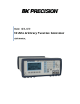
3.1 General Description
This section describes the displays, controls and connectors of the Model 4045 - Function Generator. All
controls for the instrument local operation are located on the front panel. The connectors are located on
both front and rear panels.
4
5
6
7
2
1
3
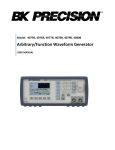
Figure 3.1 - Model 4045 Front Panel
1. Power ON-OFF
-Applies and removes AC power to the unit.
2. Display Window
-Displays all instrument data and settings on a LCD.
3. FI-F4 Keys
-Select the menu options that appear on the second line of
the LCD display. Menus differ depending on the selected
parameter, function or mode.
4. Function Keys
-Select the output waveform, Sine, Square, Triangle or Arbitrary.
5. Rotary Knob
-Used to increment/decrement numerical values or to scan
through the possible selections.
6. Modify Keys
-Used to move the cursor (when visible) to either left or right.
7. Output ON
-Controls the main output signal. The output status is displayed on the LCD.
12
3.2 Display Window
The Model 4045 has a graphic LCD display that can display up to 124 x 64 dots. When you power-on the unit
the SINE is selected and its current settings appear in the display. The bottom displays a menu that
corresponds to the function, parameter or mode displayed selected.
3.3 Front Panel Controls
The front-panel controls select, display, and change parameter, function, and mode settings. They also include
the keys you use to program and generate arbitrary waveform output.
Use the rotary input knob and the cursor movement keys to enter data into the waveform generator.
To change a setting:
1. Press the key that leads to a required item.
2. Move cursor using cursor keys to the appropriate position in the numeric field (if applicable).
3. Use the rotary input or the numerical keyboard to change the value of the displayed item. Changes take
effect immediately.
The following subsections describe the function of each front panel key and connector.
3.4 Connectors
The function generator has two BNC connectors on the front panel and two on the rear panel where you can
connect coaxial cables. These coaxial cables serve as carrier lines for input and output signals delivered to and
from the function generator.
Output Connector
Use this connector to transfer the main output signal from the function generator.
Trig In Connector
Use this connector to apply an external trigger or gate signal, depending on the waveform generator setting, to
the generator.
Sync Out Connector
Use this connector to output a positive TTL sync pulse generated at each waveform cycle.
Modulation In Connector
5V p-p signal for 100% modulation, 10Kohms input impedance with DC - >20 KHz bandwidth.
3.5 Output Connections
The waveform generator output circuits operate as a 50 ohms voltage source working into a 50 ohms load. At
higher frequencies, non terminated or improperly terminated output cause aberrations on the output
waveform. In addition, loads less than 50 ohms reduce the waveform amplitude, while loads more than 50
ohms increase waveform amplitude.
13
Model 4045 – Operating Manual
Excessive distortion or aberrations caused by improper termination are less noticeable at lower frequencies,
especially with sine and triangle waveforms. To ensure waveform integrity, follow these precautions:
1. Use good quality 50 ohms coaxial cable and connectors.
2. Make all connections tight and as short as possible.
3. Use good quality attenuators if it is necessary to reduce waveform amplitudes applied to sensitive
circuits.
4. Use termination or impedance-matching devices to avoid reflections.
5. Ensure that attenuators and terminations have adequate power handling capabilities.
If there is a DC voltage across the output load, use a coupling capacitor in series with the load. The time
constant of the coupling capacitor and load must be long enough to maintain pulse flatness.
Impedance Matching
If the waveform generator is driving a high impedance, such as the 1 Mohm input impedance (paralleled by a
stated capacitance) of an oscilloscope vertical input, connect the transmission line to a 50 ohms attenuator, a
50 ohms termination and to the oscilloscope input. The attenuator isolates the input capacitance of the device
and terminates the waveform generator properly.
3.6 MENU Keys
These keys select the main menus for displaying or changing a parameter, function or mode.
3.6.1 WAVEFORM Keys
The keys select the waveform output and displays the waveform parameter menu (frequency, amplitude and
offset). When the Arbitrary Waveform is selected, the display shows also the waveform rate.
Sine Menu
F1: FREQ
- (Frequency) Selects and displays the frequency.
Change the frequency setting using the cursor keys, rotary knob or numerical keys. If a
certain wavelength can't produce the waveform at the desired frequency, the waveform
generator displays an “Out of Range” error message.
F1: FREQ/RATE - Selects and displays the Point Rate (for Arbitrary Waveform only).
The Rate parameter governs the rate at which waveform points are executed, and thus the
frequency of the waveform output. When you set this parameter, the waveform generator
will keep that execution rate for all waveform lengths until it is changed.
F2: AMPL
- Selects the Amplitude parameter.
In Arbitrary mode this setting defines the maximum peak-to-peak amplitude of a fullscale waveform. If the waveform does not use the full scale of data (-2047 to +2047),
then its actual amplitude will be smaller.
14
Setting the Amplitude
The following equation represents the relative output amplitude voltage relationship between the
front panel amplitude peak-to-peak setting and the data point values in waveform memory:
Output voltage = amplitude p-p setting x data point value + offset
4095
Where 4095 is the data point value range in waveform memory.
Examples
F3:OFST
Front Panel
Amplitude
Setting
Data Point
Value
Relative Output
Amplitude Voltage
5 Vp-p
2047
+2.5 V
5 Vp-p
1024
+1.25 V
5 Vp-p
0
0V (offset voltage)
9 Vp-p
300
659 mV
9 Vp-p
-1000
-2.198 V
4 Vp-p
-2047
-2 V
-Selects the Offset parameter. Change the offset by using the cursor keys, rotary dial or
numerical keys. If a certain setting cannot be produced, the waveform generator will display a
“Setting Conflict” message.
Amplitude and Offset Interaction:
Amplitude and offset settings interact and are bound by hardware restrictions. In order to obtain
the desired waveform the following amplitude and offset hardware limitations must be considered:
The offset voltage has three ranges as follows:
Output Voltage
Constraints of Amplitude + Offset
Range
(Vp-p)/2 + |offset| <= 5 volts
1.01 volt to 10.00 volts
0.101 volt to 1 volt
0.010 volt to 0.100 volt
F4:SYM
(Vp-p)/2 + |offset| <= 0.5 volts
(Vp-p)/2 + |offset| <= 0.05 volts
- When the Square or Triangle waveforms are selected, the SYMMETRY is available. Change
the symmetry by using the cursor keys, rotary dial or numerical keys. If a certain setting
cannot be produced, the waveform generator will display a warning message.
15
Model 4045 – Operating Manual
Triangle Menu
3.6.2 MODE Key
Selects the output mode: CONT (Continuous), TRIG (Triggered), GATE (Gated), and BRST (Burst).
To select the output mode, press MODE, then press the function key that corresponds to the desired Mode
menu option, as shown:
Mode Menu
F1: CONT - (Continuous) - Selects continuous output.
F2: TRIG
- (Triggered) - Triggers one output cycle of the selected waveform for each trigger event.
F3: GATE - (Gated) - Triggers output cycles as long as the trigger source asserts the gate signal.
F4: BRST - (Burst) - Triggers output N output cycles for each trigger event, where N ranges from 2 to
65,535.
After selecting the TRIG , GATE or BURST menu, the trigger source menu is available:
Trigger Menu
F1: MAN - Selects manual as the trigger source. To trigger the waveform generator,
press this MAN TRIG again.
F2: INT
- Selects the internal trigger generator as the trigger source. Change the
internal trigger rate displayed with the rotary input knob.
F3: EXT
- Selects the external trigger signal as the trigger source. The trigger source
is supplied through the TRIG IN connector.
In BURST mode, the F4 displays NBRST, the number of burst pulses to be output with each trigger. The N
can be changed from 2 to 65,535.
16
3.6.3 ARBITRARY Key
When selected displays the following screen:
Arbitrary Menu
F1: FREQ/RATE
- (Frequency) Selects and displays the frequency. Change the frequency setting using
the cursor keys, rotary knob or numerical keys. If a certain wavelength can't
produce the waveform at the desired frequency, the waveform generator displays an
“Out of Range” error message. Displays the Point Rate (for Arbitrary Waveform
only). The Rate parameter governs the rate at which waveform points are executed,
and thus the frequency of the waveform output. When you set this parameter, the
waveform generator will keep that execution rate for all waveform lengths until it is
changed.
F2: AMPL
- Selects the Amplitude parameter.
In Arbitrary mode this setting defines the maximum peak-to-peak amplitude of a
full-scale waveform. If the waveform does not use the full scale of data (-2047 to
+2047), then its actual amplitude will be smaller.
F3:OFST
-Selects the Offset parameter. Change the offset by using the cursor keys, rotary dial
or numerical keys. If a certain setting cannot be produced, the waveform generator
will display a “Setting Conflict” message.
F5: ARB
- Selects the Arbitrary editing menu:
Arbitrary Editing Menu
F1: START
- Selects the arbitrary waveform start address.
F2: LENGTH
- Selects the arbitrary waveform length. Use the START and LENGTH keys to mark
a selection of the waveform memory that will be executed.
Changing one of the arbitrary parameters as start and length cause an updating of the output waveform to
the new parameters. When exiting the Arbitrary Menu by selecting a different waveform, a message to save
17
Model 4045 – Operating Manual
the Arbitrary wave will be displayed is the Arb data was changed. Select YES or NO to save the new
waveform.
3.6.4 Arbitrary EDIT Menu
Enters data for creating arbitrary waveforms. You can enter data one point at a time, as a value at an
address, draw a line from one point (a value at an address) to another point, create a predefined waveform,
or combine these to create complex waveforms. The valid data values range is -2047 to 2047. The valid
waveform memory addresses range from 1 to 1,000.
The data value governs the output amplitude of that point of the waveform, scaled to the instrument output
amplitude. Therefore, a value of 2047 corresponds to positive peak amplitude, 0 corresponds to the
waveform offset, and -2047 corresponds to the negative peak amplitude.
Edit Menu
F1: POINT
- This menu allows the point by point waveform editing. When selected, the following
menu is displayed:
Point Menu
F1: ADRS
- Select the current address in the arbitrary waveform memory.
F2: DATA
- Selects the data point value at the current address. You can change the point value from
-2047 to 2047.
F2: LINE
- This menu allows a line drawing between two selected points.
Displays the following menu:
18
F1: FROM
F2: TO
F4: EXEC
Line Menu
- Selects the starting point address.
- Selects the ending point address.
- Displays the Confirmation menu, F1:NO and F3:YES
Confirmation Menu
F3: PREDEF
- (Predefined Waveforms) Selects one of the predefined waveforms: Sine, Triangle,
Square and Noise. Displays the Predefined waveforms menu:
Predefine Menu
F1: TYPE
- Selects the waveform Sine, Triangle, Square or Noise. If Noise function is selected, a
submenu is displayed to allow adding the noise to an available waveform or to generate it
as a new noise waveform.
F2: FROM DATA
- Selects the starting point of the generated waveform and data value.
F3: LENG/SCALE - Selects the length of the predefined waveform (number of points for a full
wave). Different waveforms have different limitations on the length, as
shown in Table 3-1.
Table 3-1: Waveform Length Limits for Predefined Waveforms
Wave
Sine
Triangle
Square
Minimum length
16
16
2
19
Divisible by
4
4
2
Model 4045 – Operating Manual
Noise
16
1
F3: SCALE
- Selects the scale factor of the waveform. 100% means that the waveform spans the full
scale of -2047 to 2047. Scale factors are limited by the point data value of the starting
point and automatically calculated by the unit.
F4: EXEC
- Prompts you to confirm whether to execute the selected predefined waveform. Press NO
to abort executing the predefined waveform; press YES to execute the predefined
waveform. On the NOISE function a menu of ADD and NEW is prompt to select a new
noise waveform or to add noise to the existing waveform.
F4:SHOW WAVE
- Display the Arbitrary waveform on the full LCD display. By pressing any
button, the display returns to the MENU selection.
Full Display
3.6.5 UTILITY Key
Utility Menu
F1: RECALL
- Recalls a previously stored front-panel setup from the selected buffer. Change the buffer
number by using the rotary input knob. Valid storage buffer numbers are from 1 to 19.
Buffer 0 is the factory default setup.
F3: STORE
- Stores the current front-panel setup to the specified storage buffer. Change the buffer
number by using the data keys or the rotary input knob. Valid storage buffer numbers
range from 1 to 19.
3.6.6 SWEEP Key
Selects the Sweep Mode and allows the entering of sweep parameters as Sweep Start, Sweep Stop and
Sweep Rate.
To select the sweep mode, press SWEEP, then press the function key that corresponds to the desired Sweep
menu option, as shown:
20
Sweep Menu
F1: ON/OFF
- Operates the sweep function, selecting between Sweep On or Off.
F2: START/STOP
- Defines the Sweep Start and Stop frequencies.
F3: RATE
- Defines the Sweep Rate.
F4: LIN/LOG
- Selects the Sweep Shape, LIN or LOG.
Log Sweep Menu
3.6.7 MODULATION Key
Selects the Modulation mode AM or FM .
To select the output mode, press MODUL key, then press the function key that corresponds to the desired
menu option, as shown:
Modulation Menu
If the AM is selected, the following menu is available:
21
Model 4045 – Operating Manual
AM Menu
F1: ON/OFF
- Selects the Modulation ON or OFF operating mode.
F2: % /SHAPE - Defines the modulation depth (from 0 to 100%) and the modulation shape between
SINE, TRIANGLE or SQUARE.
F3: MOD-FREQ - Selects the modulation frequency, from 0.1Hz to 20.00KHz.
F4: EXT/INT
- Selects and enables the external modulation by an external signal applied to the
Modulation In connector.
If the FM is selected, the following menu is available:
FM Menu
F1: ON/OFF
- Selects the Modulation ON or OFF operating mode.
F2: DEV/ SHAPE
- Defines the FM deviation frequency or the modulation shape, between SINE,
TRIANGLE or SQUARE.
F3: MOD-FREQ
- Selects the modulation frequency, from 0.1Hz to 20.00KHz.
F4: EXT/INT
- Selects and enables the external modulation by an external signal applied to the
Modulation In connector.
3.7 ON Key
Use these key to control the main output signal. When the output is active, an internal LED is illuminated.
3.8 Cursor Movement Keys
22
Use these keys to move the cursor (when visible) either left or right. They are used in conjunction with the
rotary input knob to set the step size of the rotary input knob.
3.9 Rotary Input Knob
Use this knob to increase and decrease numeric values or to scroll through a list. The cursor indicates the loworder position of the displayed value which changes when you rotate the knob (for straight numeric entries
only). For other types of data, the whole value changes when you rotate the knob.
3.10 Power-On Settings
At power-on, the waveform generator performs a diagnostic self-test procedure to check itself for errors. If it
find an error, and error code and text appear in the display window. Other error codes appear when you enter
and invalid front-panel setting. For more information on error codes, see the Error Indication section.
When the waveform generator finishes the diagnostic self-test routine, it enters the local state (LOGS) and
assumes power-on default settings. Table 3-2 lists the factory default settings. You can program the waveform
generator for any settings you want at power on, as described earlier in this section.
Table 3-2
Power-on Default Settings
Key Function
Comments
FREQUENCY
100000 Hz
Wave frequency
RATE(ARB)
1 us
Sample time per point
AMPLITUDE
5.00V
Peak-to-peak output amplitude
FUNCTION
SINE
Output waveform
OFFSET
0.00V
Zero offset
REPITITION
10ms
Internal trigger rate
MODE
CONT
Waveform mode
N-BURST
2
Waves per burst
START ADRS
1
Start memory address
WAVELENGTH
500
Number of points per waveform
TRIG SOURCE
EXT
External trigger source
OUTPUT
ON
Output enabled
SWEEP
OFF
Sweep execution
23
Model 4045 – Operating Manual
MODULATION
3.11
OFF
Modulation execution
Memory
The waveform generator uses a Nonvolatile FLASH for storing arbitrary waveform data and front panel
settings. Up to 1000 points Arbitrary waveform and 20 front panel settings are stored.
Because it is impossible to 100% guarantee against loss of stored data, you should maintain a record of the
data stored in memory so that you can manually restore such data, if necessary.
3.12
Displaying Errors
At power-on, the waveform generator performs a diagnostic routine to check itself for problems. If the
diagnostic routine finds an error, an error message is displayed. The waveform generator also displays error
messages when front-panel settings are either invalid or may produce unexpected results.
Error messages for Model 4045
Message Text
Out of range
Setting conflict
Trig rate short
Empty location
SCALE too high
Protected RAM
RAM error
Save RAM
Must divide by 4
Must divide by 2
3.13
Cause
Attempt to set variable out of instrument limits.
Can't have this parameter set with some other.
Internal trigger rate too short for wave/burst.
Attempt to restore non existent setting.
Attempt to set scale too high for current dot value
Attempt to write to protected RAM range.
Error in testing RAM.
New firmware installed.
Predefined wave length must be divisible by 4.
Predefined wave length must be divisible by 2.
Using The Model 4045
This section explains how to generate various waveforms and modify the output waveform, including:
*
*
*
*
*
3.13.1
Generating a standard waveform
Creating an arbitrary waveform
Generating a waveform output
Modifying waveform output
Storing and recalling a waveform generator setup
Selecting a Standard Waveform
You can select several standard waveforms as: sine, triangle and square. Creating a standard waveform
24
requires selecting the waveform type, parameters, modes, etc., and their settings that define the waveform.
Generating a standard waveform requires the following:
* Selecting the waveform
* Setting the output frequency
* Setting the output amplitude and offset
3.13.2
Setting the Output Mode
To set the output mode:
1. Press MODE to display the Mode menu on the display window.
2. Press the function key (Fl to F4) that corresponds to the desired mode.
3.13.3 Setting the Output
To set the output channel, press the Output ON key. An internal LED is illuminated to indicate that the
Output is ON.
3.14
Examples
3.14.1 Creating an Arbitrary Waveform
You can create an arbitrary waveform using the following methods:
*
*
*
*
Enter individual data points
Draw lines between data points
Create a predefined waveform
Combine any of these methods
No need to use all 1,000 data points for one waveform. You can program any number of waveforms into
waveform memory, keeping in mind the addresses where one waveform ends and the other begins. The
waveform's frequency and amplitude are influenced by the number of data points and their value in the
waveform. For further information on how the number of data points influence the frequency and amplitude
of a waveform in execution memory, see the Setting the Frequency and Setting the Amplitude sections,
respectively.
3.14.2 Entering Individual Data Points
The most basic way to program an arbitrary waveform is to enter data points for the waveform, one data point
at a time. While this can become tedious the auto-increment function helps this process.
To enter individual data points into waveform memory, follow these steps:
1. Press ARB main key to display the selection menu.
2. Press F4 :ARB to display the arbitrary menu.
3. Press F3:EDIT to display the Edit menu.
4. Press F1:POINT, to select the point by point programming mode.
5. Press F1:ADDRESS
6. Use the rotary knob or the numerical keys to enter the address.
25
Model 4045 – Operating Manual
7.
8.
9.
Press F2:DATA.
Use the rotary knob r the numerical keys to enter the value for the data point. Valid entries range
from –2047 to 2047.
Repeat steps 5 through 9 until you finish programming your arbitrary waveform.
NOTE: Each time you press ENTER to complete a data point entry in numerical mode, the auto-increment address
advances the "A= value" by one.
3.14.3 Setting the Arbitrary Frequency
The arbitrary waveform frequency is a function of the number of data points used to run the waveform (the
length parameter in the ARBITRARY menu) and the waveform execution point rate. The waveform execution
point rate is the execution time between each point in the waveform. The total time taken to run one period of
the waveform is given by:
number of points X rate
Because the output frequency is a function of the rate and the number of points being executed, the output
frequency other waveform is:
frequency =
1
_
number of points X rate
For example, to set the output frequency to 1000Hz, given the number of data points used for the waveform
output is 1000, calculate:
rate
=
1
1000 points X 1000Hz
=l us
EXAMPLE: Setting the Output Frequency
To set the output frequency of a 1000 point waveform in execution memory to 1000Hz, set the rate to 1us:
ACTION
KEYSTROKES
Step 1. Set the output rate to 1 us (equivalent to
1000Hz output frequency)
PARAMETER
F1 :RATE
1
KHz/us
3.14.4 Setting the Amplitude
The following equation represents the relative output amplitude voltage relationship between the front-panel
amplitude peak-to-peak setting and the data point values in waveform memory:
output voltage = amplitude p-p setting x data point value + offset
4095
Where 4095 is the data point value range in waveform memory.
Table 3-4: Relative Amplitude for Waveform Output (Examples)
Front panel Amplitude Setting
Data Point Value
26
Relative Output Amplitude Voltage
5V peak-to-peak
5V peak-to-peak
10V peak-to-peak
3.14.5
2047
0
2047
2.5V positive peak
0V (offset voltage)
5V positive peak
Executing an Arbitrary Waveform
To load a waveform into execution memory, specify its starting address and length in the ARBITRARY
menu.
1.
2.
3.
4.
5.
3.14.6
Select the channel to ON.
Press the ARB key and select the F4:ARB function.
Press F1:START to set the address. Valid entries range from 1 to 999.
Press F2:LENGTH to display the length of the waveform.
Use the rotary input knob or the numerical keys to enter the waveform length. Valid entries range from
2 to 1000.
Using Voltage Offset
Through the offset parameter you can add a positive or negative DC level to the output waveform.
To set voltage offset:
1.
2.
3.
Press Waveform to display the menu.
Press F3 :OFST to display the offset setting.
Use the rotary input knob or the numerical keys to set the voltage offset.
To turn the voltage offset OFF, repeat the steps above, but set the offset voltage level to 0.
3.14.7 Storing and Recalling a Waveform Generator Setup
You can store up to 20 front-panel setups in a part of nonvolatile Flash known as the settings storage memory.
When you recall a stored setup, the front-panel settings change to match the settings in the stored setup. These
stored and recalled settings include the starting address and length of the arbitrary memory that is loaded in
the execution memory.
Storing Setups
To store the front-panel setup:
1. Press UTILITY to display the menu.
2. Press F2:STORE to select the Store mode.
3. Use the rotary input knob to select a buffer number. Valid buffer numbers range from 1 to 19. Buffer 0
is a read-only buffer that contains the power-on settings listed in Table 3-3.
The waveform generator does not warn you when you store a setup into a settings buffer that is already
occupied.
Recalling Setups
To recall stored front-panel setup:
1. Press UTILITY to display the menu.
27
Model 4045 – Operating Manual
2. Press F1:RECALL to select the Recall mode.
3. Use the rotary input knob to select a buffer number. Valid buffers numbers range from 0 to 19. Buffer 0
is a read-only buffer that contains the power-on settings listed in Table 3-3.
28
Section 4
Programming
4.1 Overview
This section provides detailed information on programming the Model 4045 via the USB interface.
4.2 Device States
The device may be in one of the two possible states described below.
4.2.1 Local State (LOCS)
In the LOCS the device may be operated from the front panel.
4.2.2 Remote State (REMS)
In the REMS the device may be operated from the USB interface. Actuating any front panel key will cause
the device state to revert to the LOCS.
4.3 Message Exchange Protocol
The device decodes messages using the Message Exchange Protocol similar to the one defined in IEEE
488.2. The following functions implemented in the MEP must be considered:
4.3.1 The Input Buffer
The device has a 128-byte long cyclic input buffer. Decoding of remote messages is begun as soon as the
input buffer is not empty, that is, as soon as the controller has sent at least one byte to the device. Should
the input buffer be filled up by the controller faster than the device can remove the bytes and decode them,
the bus handshake (CTS/RTS) is used to pause data transfer until room has been made for more bytes in the
buffer. This prevents the controller from overrunning the device with data.
4.3.2 The Output Queue
The device has a 100-byte long output queue in which it stores response messages for the controller to read.
If at the time a response message is formatted the queue contains previously formatted response messages,
such that there is not enough place in the queue for the new message, the device will put off putting the
message in the queue until there is place for it.
29
Model 4045 – Operating Manual
4.3.3 Response Messages
The device sends a Response Message in response to a valid query. All queries return a single Response
Message Unit. In only one case is the Response Message generated when the response is read (as opposed
to when the response is parsed), and this is when querying Arbitrary Waveform data. All other queries
generate the Response Message when they are parsed.
4.4 Instrument Identification
The *IDN? common query is used to read the instrument's identification string. The string returned is as
follows:
B&K PRECISION,MODEL 4045,0,V0.1
The “V0.1” reflects the firmware version number and will change accordingly.
4.5 Instrument Reset
The *RST common command effects an instrument reset to the factory default power up state.
4.6
Command Syntax
4.6.1 General Command Structure
A Program Message is defined as a string containing one Program Message Units, which is an instrument
command or query. The Program Message is terminated by the Program Message Terminator.
The Program Message Terminator consists of optional white space characters, followed by the Linefeed
(LF) character (ASCII 0A);
The Program Message Unit can be divided into three sections as follows:
a) Program Header
The Program Header represents the operation to be performed, and consists of ASCII character mnemonics.
Two types of Program Headers are used in the Model 4045: Instrument-control headers and Common
Command and Query headers. Common Command and Query Program Headers consist of a single
mnemonic prefixed by an asterisk ('*').
The mnemonics consist of upper - or lower-case alpha characters.
Example: The command to set the frequency to 1KHZ may be written in the following ways:
FREQ 1KHZ
FREQ 1000HZ
FREQ 1000
FREQ 1E3
freq 1khz
30
freq 1000hz
freq 1000
freq 1e3
b) Program Header Separator
The Program Header Separator is used to separate the program header from the program data. It consists of
one or more white space characters, denoted as <ws>. Typically, it is a space.
c) Program Data
The Program Data represent the values of the parameters being set, for example, the '1KHZ' in the above
examples. Different forms of program data are accepted, depending on the command. The Program Data
types used in the instrument are:
i) Character program data
This form of data is comprised of a mnemonic made up of lower - or upper-case alpha characters. As with
Program Header mnemonics, some Character Data mnemonics have short and long forms. Only the short
or the long form may be used.
ii) Boolean data
Boolean data indicate that the parameter can take one of two states, ON or OFF. The parameter may be
character type ON or OFF or numeric. A numeric value is rounded to an integer. A non-zero result is
interpreted as 1 (ON), and a zero result as 0 (OFF). Queries return the values 0 or 1.
iii) NRf
This is a decimal numeric data type, where
NR1 indicates an integer number,
NR2 indicates a fixed point real number, and
NR3 indicates a floating point real number.
iv) Numeric value program data
This data type defines numeric values, as well as special cases of Character Data. Numeric values may be
specified in any of Integer, Fixed Point or Floating Point format. All parameters which have associated
units accept a suffix, which may be specified using upper or lower-case characters. When the suffix is not
specified, the numeric value is accepted in the default units, which are Hertz for frequency, Seconds for
time, and Volts for voltage. To set the frequency to 1KHz we can send one of the following commands:
FREQ 1000
FREQ 1E3
The special forms of character data accepted as numbers are
MAXimum: sets the parameter to its maximum value.
MINimum: sets the parameter to its minimum value.
For example, to set the frequency to it's maximum value we can send the command
FREQ MAX
vi) Arbitrary Block Data
31
Model 4045 – Operating Manual
The Arbitrary block data type is used to send arbitrary waveform data to the instrument. In this
data type, the waveform points are specified in binary format, and each point consists of two
bytes. Two types of arbitrary block data are defined (by IEEE 488.2):
Definite Form
ִ
The Definite Form has the structure:
-#-Byte Count Length - Byte Count - 8-bit byte
The Byte Count Length consists of a single ASCII digit from 1 to 9. It tells the parser how many
digits are in the Byte Count.
The Byte Count is a decimal integer made up of the number of digits specified in the Byte Count
Length. It tells the parser how many 8-bit bytes are being sent.
Indefinite Form
The Indefinite Form has the structure:
- # - 0 – 8-bit byte – LF
Some Program Message Units either require, or can accept, more than one data element. Program data
elements are separated from each other by the Program Data Separator. It is defined as optional white space
characters followed by a comma (','), which in turn is followed by optional white space characters.
There are two types of Program Message Units: Command Message Units and Query Message Units. A
Query differs from a Command in that the Program Header is terminated with a question mark ('?'). For
example, the frequency might be queried with the following query:
FREQ?
Some Query Message Units accept data, giving the device more specific information about what is being
queried. In many cases the Query Message Unit may optionally be supplied with the MIN or MAX
mnemonics as data. This tells the device to return the minimum or maximum value to which the parameter
may currently be set. For example,
FREQ? MAX
will return the maximum value to which the frequency may currently be set.
Not all Program Message units have query forms ( for example, SAV), and some Program Message Units
might have only the query form (for example IDN?).
The instrument puts the response to the query into the output queue, from where it may be read by the
controller.
4.7 Status Reporting
The instrument is capable of reporting status events and errors to the controller.
32
4.7.1 The Error Queue
The error queue is used to store codes of errors detected in the device. It is implemented as a cyclic buffer
of length 10. The error queue is read with the following query:
ERR?
The first error in the queue is returned, and the queue is advanced.
4.7.2 Error Codes
The negative error codes are defined by SCPI. Positive codes are specific to the instrument.
The error message is returned in the form:
<error number>,"<error description>"
A table of error numbers and their descriptions is presented here.
No error reported
0 - No error
Command Errors
A command error is in the range -199 to -100, and indicates that a syntax error was detected. This includes
the case of an unrecognized header.
-100
-101
-102
-103
-104
-108
-109
-110
-111
-112
-113
-120
-121
-123
-124
-128
-131
-134
-138
-140
-141
Command Error
Invalid character
Syntax error
Invalid separator
Data type error
Parameter not allowed
More parameters than allowed were received
Missing parameter
Fewer parameters than necessary were received
Command header error
Header separator error
Program mnemonic too long
The mnemonic must contain no more than 12 characters.
Undefined header
Numeric data error
Invalid character in number
Exponent too large
Too many digits
Numeric data not allowed
A different data type was expected
Invalid suffix
Suffix too long
Suffix not allowed
Character data error.
Invalid character data.
33
Model 4045 – Operating Manual
-144
-148
-158
-161
-168
-178
Incorrect character data were received.
Character data too long
Character data may contain no more than 12 characters.
Character data not allowed
String data not allowed
Invalid block data
An error was found in the block data
Block data not allowed
Expression data not allowed
Execution Errors
An execution error indicates that the device could not execute a syntactically correct command, either since
the data were out of the instrument's range, or due to a device condition.
-200
-211
-220
-221
-222
-223
-224
Execution error
An attempt was made to RECALL the contents of an uninitialized stored setting buffer.
Trigger ignored.
The *TRG common command was ignored due to the device not being in the correct
state to execute the trigger.
Parameter error.
A parameter is in the correct range, but conflicts with other parameters.
Settings conflict.
The parameter is out of range due to the current instrument state.
Data out of range.
Too much data.
The arbitrary waveform memory limit has been exceeded.
Illegal parameter value.
The parameter value must be selected from a finite list of possibilities.
Device-Specific Errors
An error specific to the device occurred.
-315
-330
-350
Configuration memory lost.
Device memory has been lost.
Self-test failed.
Queue overflow.
Error codes have been lost due to more than 10 errors being reported without being read.
Query Errors
A query error indicates that the output queue control has detected a problem. This could occur if either an
attempt was made to read data from the instrument if none was available, or when data were lost. Data
could be lost when a query causes data to be formatted for the controller to be read, and the controller sends
more commands without reading the data.
-410
-420
Query INTERRUPTED.
Data were sent before the entire response of a previous query was read.
Query UNTERMINATED.
34
An attempt was made to read a response before the complete program message meant to
generate that response was sent.
Warnings
The execution of some commands might cause an undesirable instrument state. The commands are
executed, but a warning is issued.
500
510
Trigger rate short
Output overload
"Trigger rate short" means that the period of the waveform is larger than the value of the internal trigger
rate. Thus not every trigger will generate a cycle (or burst) of the waveform.
4.8 Common Commands
4.8.1 System Data Commands
a) *IDN? - Identification query
The identification query enables unique identification of the device over the GPIB. This query should
always be the last in a program message. It returns a string with four fields:
Manufacturer name
Model name
Serial number (0 if not relevant)
Version number
Command
Type:
Syntax:
Response:
4.8.2
Common Query
*IDN?
B&K PRECISION, MODEL 4045,0,V1.1
Internal Operation Commands
a) *RST - Reset command
The Reset command performs a device reset. It causes the device to return to the factory default power up
state.
Type:
Syntax:
Common Command
*RST
4.8.3 Device Trigger Commands
a) *TRG - Trigger command
This command is analogous to the IEEE 488.1 Group Execute Trigger interface message, and has
the same effect. It is used to trigger the device to output a wave, and is accepted only when the
trigger mode is set to Trigger, Gate or Burst, and the trigger source is set to BUS.
Type:
Common Command
35
Model 4045 – Operating Manual
Syntax:
*TRG
4.8.4 Stored Settings Commands
a) *RCL - Recall instrument state
This command is used to restore the state of the device to that stored in the specified memory location.
Arguments
Type
<NRf>
Range
0 to 49. Non integer values are
rounded before execution
Type:
Syntax:
Example:
Common Command
*RCL<ws><NRf>
*RCL 0 (Recall default state)
*RCL 49
Stored setting location 50 stores the last instrument setting before power down.
b) *SAV - Save instrument state
This command is used to store the current instrument state in the specified memory location.
Arguments
Type:
<NRf>
Range:
1 to 49. Non integer values are rounded before execution
Type:
Common Command
Syntax:
*SAV<ws><NRf>
Example:
*SAV 25
Stored setting location 0 stores the factory defaults, and is a read-only location. Location 50 stores a copy
of the current instrument setting, and it, too, is read-only.
4.9 Instrument Control Commands
Instrument control commands are grouped into logical subsystems according to the SCPI instrument
Model. The commands are comprised of mnemonics indicating the subsystem to which the command
belongs, and the hierarchy within that subsystem. When the command is to be referred to the Root node, it
should be prefixed with a colon (:). Mnemonics appearing in square brackets [...] are optional. The '|'
character is used to denote a choice of specifications. The '<ws>' is used to denote a white space character.
4.9.1 Default Subsystem
The Source Subsystem controls the frequency, voltage, amplitude modulation and clock source. The
command structure is as follows:
FUNCtion
FREQuency
AMPLitude
OFFSet
DCYCle
SINusoid|SQUare|TRIangle||ARBitrary
<numeric value>
<numeric value>
<numeric value>
<numeric value>
36
MODE
TRIG
TRAte
BURSt
CONT/ TRIG / GATE / BRST
INT / EXT
<numeric value>
<numeric value>
MODULation OFF/AM/FM/INT/EXT
MODFRequency <numeric value>
MODSHape
SIN/TRI/ SQU
DEViation
<numeric value>
DEPTh
<numeric value>
SWSTArt
SWSTOp
SWRAte
SWEep
<numeric value>
<numeric value>
<numeric value>
ON/OFF/LIN/LOG
4.9.1.1 Frequency
FREQuency <frequency>
The frequency command controls the frequency of the output waveform.
Arguments
Type:
Units:
Range:
Numeric
MHz, KHz, Hz (default)
For SIN and SQU - 10uHz to 31MHz,
For TRI – 10uHz to 500KHz,
For ARB - Dependent on the Point Rate and Wavelength.
Fmax = 1/(20nS * Wavelength)
Fmin = 1/(50S * Wavelength)
Rounding:
The value is rounded to 10 digits (DDS) or 4 digits (ARB).
Command Type: Setting or Query
Setting
Syntax:
FREQuency<ws><frequency>[units]
FREQuency<ws>MINimum|MAXimum
Examples:
FREQ 5KHZ
FREQ 5E3
FREQ MAXIMUM
FREQ MIN
Query
Syntax:
FREQuency?[<ws>MAXimum|MINimum]
Examples:
FREQ?
FREQ? MAX
Response:
NR3
Considerations:
1) The MIN | MAX arguments should be used for ARB waveform only in a Program Message
that does NOT contain Program Message Units specifying Arbitrary Point Rate or Wavelength,
since the MAXimum or MINimum value is calculated at the time the command is parsed.
2) The MIN and MAX arguments refer to currently settable minimum or maximum.
3) FIXed is alias for CW.
37
Model 4045 – Operating Manual
4.9.1.2 Point Rate
RATE <point rate>
This command is used to set the point rate. It is coupled with the frequency of the waveform by the
relation:
Frequency = 1/(Point Rate * Wavelength)
Thus changing the point rate will result in a change in frequency.
Arguments
Type:
Units:
Range:
Rounding:
Command Type:
Setting
Syntax:
Examples:
Query
Syntax:
Response:
Numeric
s, ms, us, ns
20ns to 50s
to 4 digits
Setting or Query
RATE<ws><point rate>[units]
RATE<ws>MINimum|MAXimum
RATE 100NS
RATe?[<ws>MINimum|MAXimum]
NR3
Note: You can alternately use the :ARB:PRATe command.
4.9.1.3 Amplitude
AMPLitude <p-p amplitude>
The amplitude command is used to set the peak-to-peak amplitude of the output waveform. Note that
the amplitude and the offset are limited by the relation
Peak Amplitude + |Offset| <= 5V
Arguments
Type:
Units:
Range:
Rounding:
Command Type:
Setting
Syntax:
Examples:
Query
Syntax:
Numeric
V, mV, VPP, mVPP
10mV to 10V
1mV from 10mV to 999mV. 10mV from 1V to 10V.
Setting or Query
AMPLitude<ws><amplitude>[units]
AMPLitude<ws>MINimum|MAXimum
AMPL 2.5
AMPL 2.5V
AMPL MAX
AMPLitude? <ws>MINimum|MAXimum]
38
Examples:
Response:
AMPL?
AMPL? MAX
NR2
Considerations:
1) The MAXimum amplitude is dependent on the offset.
2) The MAX and MIN arguments should not be used in a program message containing an OFFSet
command, since these values are evaluated during parsing, based on the current value of the offset.
4.9.1.4 Offset
OFFSet <offset>
The offset command is used to set the DC offset of the output waveform. Note that the amplitude and
the offset are limited by the relation
Peak Amplitude + |Offset| ≤ 5V
Arguments
Type:
Units:
Range:
Rounding:
Command Type:
Setting
Syntax:
Examples:
Query
Syntax:
Examples:
Response:
Numeric
V, mV
10mV to 4.5V
to 10mV
Setting or Query
OFFSet<ws><offset>[units]
OFFSet<ws>MINimum|MAXimum
OFFS 2.5
OFFS 2.5V
OFFS MAX
OFFSet?[<ws>MINimum|MAXimum]
OFFS?
OFFS? MAX
NR2
Considerations:
1) The MAXimum offset is dependent on the amplitude.
2) The MAX and MIN arguments should not be used in a program message containing an
AMPLitude command, since these values are evaluated during parsing, based on the current value
of the amplitude.
4.9.1.5 Function
FUNCtion
The function command is used to set the type of waveform to be generated by the instrument.
Command Type: Setting or Query
Setting
Syntax:
FUNCtion<WS><OPTION>
Examples: FUNC SIN
FUNC ARB
Query
39
Model 4045 – Operating Manual
Syntax:
Examples:
Response:
FUNCtion?
FUNC?
SIN|TRI|SQU|ARB
The following functions are available:
SINusoid,SQUare, TRIangle, ARBitrary
4.9.1.6 Modulation
The following commands control the modulation:
MODULation
This command activates or deactivates modulation:
Command Type: Setting or Query
Setting
Syntax:
MODULation OFF|AM|FM|INT|EXT
Examples:
MODULation FM
MODULation OFF
Query
Syntax:
MODULation?
OFF
|
Response:
AM INT
AM EXT
FM INT
FM EXT
|
|
|
DEPTh
This command sets the AM modulation depth in %
Arguments
Type:
Units:
Range:
Rounding:
Command Type:
Setting
Syntax:
Examples:
Query
Syntax:
Response:
Numeric
none (implied %)
0 to 100
To integer
Setting or Query
DEPTh<ws><percent depth>
DEPTh<ws>MINimum|MAXimum
DEPTh 50
DEPTh?[<ws>MINimum|MAXimum]
NR3
MODFRequency
This command sets the AM and FM modulating waveform frequency
Arguments
Type:
Units:
Range:
Rounding:
Numeric.
MHz, KHz, Hz (default)
Fmax = 20 KHz
Fmin = 0.01 Hz
The value is rounded to 4 digits.
40
Command Type: Setting or Query
Setting
Syntax:
MODFR<ws><frequency>[units]
MODFR<ws>MINimum|MAXimum
Examples:
MODFR 5KHZ
MODFR 5E3
MODFR MAXIMUM
MODFR MIN
Query
Syntax:
MODFR?[<ws>MAXimum|MINimum]
Examples:
MODFR?
MODFR? MAX
Response:
NR3
MODSHape
This command selects the modulating waveform shape
Arguments
Type:
Options:
Command Type:
Setting
Syntax:
Examples:
Query
Syntax:
Response:
Character
SINusoid, TRIangle, SQUare
Setting or Query
MODSHape<ws><SIN|TRI|SQU>
MODSHape SIN
MODSHape TRI
MODSHape?
SIN|TRI|SQU
DEViation
This command sets the FM modulation deviation
Arguments
Type:
Numeric.
Units:
MHz, KHz, Hz (default)
Range:
Dependent on the carrier frequency, up to 1.56MHz.
Fmax = carrier frequency
Fmin = 10 uHz
Rounding:
The value is rounded to 4 digits.
Command Type: Setting or Query
Setting
Syntax:
DEViation<ws><frequency>[units]
DEViation<ws>MINimum|MAXimum
Examples:
DEV 5KHZ
DEV 5E3
DEV MAXIMUM
DEV MIN
Query
Syntax:
DEViation?[<ws>MAXimum|MINimum]
Examples:
DEV?
DEV? MAX
Response:
NR3
4.9.1.7 Sweep control
41
Model 4045 – Operating Manual
The following commands control the sweep functionality:
SWEep
This command activates or deactivates sweep:
Arguments
Type:
Command Type:
Setting
Syntax:
Examples:
Query
Syntax:
Response:
Boolean
Setting or Query
SWE<ws>ON|OFF|LIN|LOG
SWE ON
SWE LIN
SWE?
OFF|LIN|LOG
Note: Sweep cannot be activated in ARB or if FM is active.
SWRAte
This command sets the time for one complete sweep:
Arguments
Type:
Units:
Range:
Rounding:
Command Type:
Setting
Syntax:
Examples:
Query
Syntax:
Response:
Numeric
S, mS, uS, nS
10mS to 500S
to 4 digits
Setting or Query
SWRAte<ws><time>[units]
SWRAte<ws>MINimum|MAXimum
SWRAte 50MS
SWRAte?[<ws>MINimum|MAXimum]
NR3
SWSTArt
This command sets the start frequency of the sweep:
Arguments
Type:
Units:
Range:
Numeric.
MHz, KHz, Hz (default)
Dependent on the frequency range of the current function.
Rounding: The value is rounded to 4 digits.
Setting or Query
Command Type:
Setting
Syntax:
SWSTArt<ws><frequency>[units]
SWSTArt<ws>MINimum|MAXimum
Examples:
SWSTArt 5KHZ
SWSTArt 5E3
SWSTArt MAXIMUM
SWSTArt MIN
Query
Syntax:
SWSTArt?[<ws>MAXimum|MINimum]
42
Examples:
Response:
SWSTArt ?
SWSTArt ? MAX
NR3
SWSTOp
This command sets the stop frequency of the sweep:
Arguments
Type:
Units:
Range:
Rounding:
Command Type:
Setting
Syntax:
Examples:
Query
Syntax:
Examples:
Response:
Numeric
MHz, KHz, Hz (default)
Dependent on the frequency range of the current function.
The value is rounded to 4 digits.
Setting or Query
SWSTOp<ws><frequency>[units]
SWSTOp<ws>MINimum|MAXimum
SWSTOp 5KHZ
SWSTOp 5E3
SWSTOp MAXIMUM
SWSTOp MIN
SWSTOp?[<ws>MAXimum|MINimum]
SWSTOp ?
SWSTOp ? MAX
NR3
4.9.1.8 Duty Cycle
DCYCle <duty cycle value>
This command is used to set the duty-cycle of the square wave or the symmetry of triangular wave.
The value is given in percent .
Arguments
Type:
Units:
Range:
Rounding:
Command Type:
Setting
Syntax:
Query
Syntax:
Response:
Numeric
None (percent implied)
20 to 80
To integer
Setting or Query
DCYCle <ws><duty cycle value>
DCYCle <ws>MINimum|MAXimum
DCYCle?[<ws>MINimum|MAXimum]
NR3
4.9.1.9 Output State
:OUT <state 0,1>
This command controls whether the output is ON or OFF.
43
Model 4045 – Operating Manual
Arguments
Type:
Boolean
Command Type: Setting or Query
Setting
Syntax:
:OUT<ws>ON|1|OFF|0
Examples: :OUT ON
:OUT OFF
Query
Syntax:
:OUT?
Response:
0|1
4.9.1.10 Trigger Mode
MODE <trigger mode>
This command is used to set the trigger mode.
Arguments
Type:
Options:
Character
CONTinuous
TRIGger
GATE
BURSt
Command Type: Setting or Query
Setting
Syntax:
MODE<ws><option>
Examples:
MODE CONT
MODE BURS
Query
Syntax:
MODE?
Response:
CONT|TRIG|GATE|BURS
4.9.3.2 Trigger Source
TRIGger<trigger source>
This command is used to select the trigger source, for use in the Trigger, Gate and Burst trigger modes.
Arguments
Type:
Options:
Character
INTernal - Internal trigger
EXTernal - External trigger
Command Type: Setting or Query
Setting
Syntax:
TRIGger<ws><option>
Examples:
TRIG EXT
TRIG INT
Query
Syntax:
TRIGger?
Response:
INT|EXT
4.9.3.3 Burst Count
44
BURSt <burst count>
Used to set the number of cycles to be output in the BURST mode. It is not a standard SCPI command.
Arguments
Type:
Range:
Rounding:
Command Type:
Setting
Syntax
Examples
Query
Syntax:
Response:
Examples:
Numeric
2 to 65535
To integer value
Setting or Query
BURSt<ws><value>
BURS 100
BURS MAXIMUM
BURSt?[<ws>MAXimum|MINimum]
NR1
BURST?
BURS? MAX
4.9.3.4 Internal Trigger Rate
TRAte <trigger rate>
Sets the rate of the internal trigger.
Arguments
Type:
Units:
Range:
Rounding:
Command Type:
Setting
Syntax:
Examples:
Query
Syntax:
Response:
Examples:
Numeric
S, mS, uS, nS
1E-6S to 100S
to 4 digits
Setting or Query
TRAte<ws><value>[units]
TRAte<ws>MINimum|MAXimum
TRAte 10E-6
TRAte MIN
TRAte?[<ws>MINimum|MAXimum]
NR3
TRAte?
TRAte? MIN
4.9.4 Arbitrary Subsystem
The Arbitrary subsystem is not part of the SCPI standard. It was developed to suit the needs of the
instrument. Within this subsystem are found commands to:
1) control the point rate, start address, wavelength, and synchronization pulse address;
2) set values of the arbitrary waveform, either discretely or using predefined, copy or draw functions;
3) protect an area of waveform memory;
4) set the state of the automatic update and increment features;
5) update the waveform.
The following shows the structure of the ARBitrary subsystem:
:ARBitrary
45
Model 4045 – Operating Manual
:PRATe <numeric value>
:ADDRess <numeric value>
:DATA <numeric value>|<arbitrary block>
:DRAW <numeric value>,<numeric value>
:PREDefined <shape>,<start address>,<length>,<scale>
:STARt <numeric value>
:LENGth <numeric value>
:SAVe
4.9.4.1 Point Rate
ARBitrary:PRATe <point rate>
This command is used to set the point rate. It is coupled with the frequency of the waveform by the
relation:
Frequency = 1/(Point Rate * Wavelength)
Thus changing the point rate will result in a change in frequency.
Arguments
Type:
Units:
Range:
Rounding:
Command Type:
Setting
Syntax:
Examples:
Query
Syntax:
Response:
Numeric
S, mS, uS, nS
20nS to 50S
to 4 digits
Setting or Query
:ARBitrary:PRATe<ws><point rate>[units]
:ARBitrary:PRATe<ws>MINimum|MAXimum
:ARB:PRAT 100NS
:ARBitrary:PRATe?[<ws>MINimum|MAXimum]
NR3
Note: You can alternately use the RATE command.
4.9.4.2 Address
:ARBitrary:ADDRess <address>
This command sets the current address of the waveform. It is used to determine where arbitrary data
are to be written.
Arguments
Type:
Range:
Rounding:
Command Type:
Setting
Syntax:
Examples:
Query
Numeric
1 to 1,000
to integer value
Setting or Query
:ARBitrary:ADDRess<ws><address>
:ARBitrary:ADDRess<ws>MINimum|MAXimum
:ARB:ADDR 100
46
Syntax:
Response:
:ARBitrary:ADDRess?[<ws>MINimum|MAXimum]
NR1
4.9.4.3 Data
:ARBitrary:DATA <data>
This command is used to set the values of the waveform.
Arguments
Type:
Numeric Range:
Rounding:
Command Type:
Setting Syntax
Numeric:
Example
Query
Syntax:
Response:
Numeric. Definite form arbitrary block. Indefinite form arbitrary block
-2047 to 2047 ASCII
to integer value
Setting or Query
:ARBitrary:DATA<ws><numeric>{[,<numeric]}
:ARB:DATA 100,200,1000,2000,-2000
:ARBitrary:DATA?<ws><number of points>[, ASCii]
Data are returned in the decimal numeric form.
4.9.4.4 Line Draw
:ARBitrary:DRAW <start address>,<end address>
memory.
This command is used to generate a straight line between two points in the arbitrary waveform
Arguments
Type:
Range:
Rounding:
Command Type:
Setting
Syntax:
Example:
Numeric.
1 to 500,000
to integer value
Setting only
:ARBitrary:DRAW<ws><start address>, <end address>
:ARB:DRAW 1,1000
Considerations:
1) The value of the data at the start and end points must first be set by the user, using the
:ARB:DATA command.
2) The range of the straight line cannot overlap with protected memory.
3) The end address must be greater than the start address.
4.9.4.5 Predefined waveforms
:ARB:PRED <shape>,<start address>,<length>,<scale>
This command is used to load the waveform memory with a specific type of waveform.
Arguments
Shape
Type:
Character
47
Model 4045 – Operating Manual
Options:
Start Address
Type:
Range:
Rounding:
Length
Type:
Range
SIN:
SQU:
TRI:
NOIS:
ANO:
Rounding:
Scale
Type:
Range:
Rounding;
Command Type:
Setting
Syntax:
Examples:
SINusoid
SQUare
TRIangle
NOISe (Pseudo-Random Noise)
ANOise (Noise added to the current waveform)
Numeric. The MIN and MAX forms both set the address to 1
1 to 1000
to integer value
Numeric
16 to 1000; divisible by 4
2 to 1000; divisible by 2
16 to 1000; divisible by 4
16 to 1000,
16 to 1000,
to integer value.
Numeric. MIN sets the scale to 1; MAX sets the scale to 100
1 to 100 (See considerations)
to integer value.
Setting only
:ARBitrary:PREDefined<ws> <shape>, <start>, <length>,<scale>
:ARB:PRED SIN,1,1e3,100
Considerations:
1) The start address and the length must meet the specification:
Start address + Length - 1 <= 1,000
2) The 'scale' refers to the scaling of the waveform as a percentage of full scale. A scale of 100% will,
under the correct conditions, generate a waveform whose data values range from -2047 to +2047.
These 'correct conditions' are set by the 'offset' value. This offset is the value of the data at the start
address, and determines the maximum scale settable. The following table shows the data values
required in order to achieve maximum scale.
SHAPE
SIN
SQU
TRI
NOIS
DATA
0
0
0
0
4.9.4.6 Start Address
:ARBitrary:STARt <start address>
This command sets the start address of the waveform to be run.
Arguments
Type:
Range:
Rounding:
Command Type:
Numeric
1 to 999
to integer value
Setting or Query
48
Setting
Syntax:
Example:
Query
Syntax:
Examples:
Response:
:ARBitrary:STARt<ws><start address>
:ARBitrary:STARt<ws>MINimum|MAXimum
:ARB:STAR 100
:ARBitrary:STARt?[<ws>MINimum|MAXimum]
:ARB:START?
:ARB:STAR? MIN
NR1
Considerations: The start address and length must meet the condition:
Start Address + Length - 1 <= 1000
4.9.4.7 Wavelength
:ARBitrary:LENGth <length>
This command sets the length of the waveform being run.
Arguments
Type:
Range:
Rounding:
Command Type:
Setting
Syntax:
Example:
Query
Syntax:
Example:
Response:
Numeric
2 to 1000
to integer value
Setting or Query
:ARBitrary:LENGth<ws><length>
:ARBitrary:LENGth<ws>MINimum|MAXimum
:ARB:LENG 1E3
:ARBitrary:LENGth?[<ws>MINimum|MAXimum]
:ARB:LENG?
NR1
Considerations:
1) Changing the wavelength will change either the frequency.
2) The minimum wavelength is 2.
4.9.4.8 Save
:ARBitrary:SAVe
This command is used to save all unsaved arbitrary waveform data into non-volatile memory..
Arguments
Type:
none
Command Type: Setting only
Setting
Syntax:
:ARBitrary: SAVe
4.9.5 Error Queue Reading
49
Model 4045 – Operating Manual
ERRor?
This query returns the first entry in the error queue, and removes that entry from the queue.
Command Type: Query only
Query
Syntax:
ERRor?
Response:
<Error number>, “<error description>”
50
This image cannot currently be displayed.
51
Model 4045 – Operating Manual
4.10 USB Virtual COM Programming
4.10.1 General
The INSTALLATION section of this manual describes the USB virtual COM connection for the
instrument.
A USB virtual COM port is a software interface that enables applications to access a USB device as if it
were a built-in serial port.
The baud rate is the bit rate during the transmission of a word in bits per second. Different devices use
many baud rates, but the baud rates of the two devices that are connected must be the same. The instrument
is set to a fixed baud rate of 19200 (115200 for instrument with USB virtual COM) as described in Section
3, Operating Instructions.
Data signals over the serial interface use a voltage of +3V to +25V to represent a zero (called a space) and a
voltage of -3V to -25V to represent a one (called a mark). Handshake and control lines use +3V to +25V to
indicate a true condition and -3V to -25V to indicate a false condition.
When no data is being transmitted, the idle state of the data lines will be the mark state. To transmit a byte,
the transmitting device first sends a start bit to synchronize the receiver.
4.10.2 USB Virtual COM Operation
The USB virtual COM standard is not very specific about many of the handshaking signals and it is
therefore usually necessary to refer to the manuals for both of the devices being connected to determine the
exact pin out, signal definition, and signal direction for the devices.
The instrument is programmed by sending ASCII coded characters to the instrument.
When the instrument is in the remote mode remote command input has priority over any front panel
control. Therefore, as long as the serial interface is continuously supplied with data, the keyboard will
appear to be inoperative to the user.
The instrument accepts a carriage return (CR) as an end of string (EOS) terminator and sends both a CR
and LF as the EOS terminator.
52