1
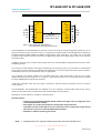
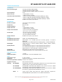
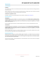
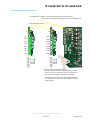
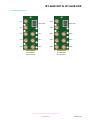
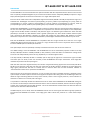
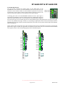
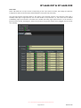
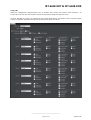
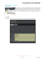
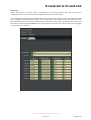
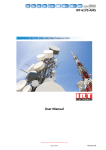
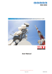
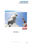
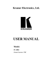
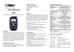
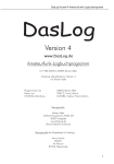
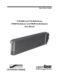
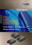
IRT-6638-DDT & IRT-6638-DDR
8-Channel 3G/HD/SD-SDI / ASI Fibre Optic Link
User Manual
I.R.T. Communications Pty Ltd | www.irtcommunications.com
Page 1 of 21
Revision 00
IRT-6638-DDT & IRT-6638-DDR
8-Channel 3G/HD/SD-SDI / ASI Fibre Optic Link
Revision History:
Revision
00
Date
08/12/2014
By
AL
Change Description
Original Issue.
Applicable to:
Firmware ≥
Revision 1.1
I.R.T. Communications Pty Ltd | www.irtcommunications.com
Page 2 of 21
Revision 00
IRT-6638-DDT & IRT-6638-DDR
USER MANUAL
Table of Contents:
Section
Page
Revision History
Operational Safety
openGear® Introduction
General Description
Technical Specifications
Configuration
DIP Switch Settings
IRT-6638-DDT
IRT-6638-DDR
Installation
Signal Connections
IRT-6638-DDT
IRT-6638-DDR
Fibre Optic Connection
Front Edge LED and Switch Locations
Rear Assembly Layouts
Operation
Front Edge LED Indicators
DashBoard™ Software Control
IRT-6638-DDT DashBoard™ Screenshots
IRT-6638-DDR DashBoard™ Screenshots
Maintenance & Storage
Warranty & Service
2
4
5
6
7
8
8
8
9
10
10
10
10
10
11
12
13
14
15
15
18
21
21
This instruction book applies to units fitted with firmware ≥ Revision 1.1.
I.R.T. Communications Pty Ltd | www.irtcommunications.com
Page 3 of 21
Revision 00
IRT-6638-DDT & IRT-6638-DDR
OPERATIONAL SAFETY
WARNING
Operation of electronic equipment involves the use of voltages and currents that
may be dangerous to human life. Note that under certain conditions dangerous
potentials may exist in some circuits when power controls are in the OFF position.
Maintenance personnel should observe all safety regulations.
Do not make any adjustments inside equipment with power ON unless proper
precautions are observed. All internal adjustments should only be made by suitably
qualified personnel. All operational adjustments are available externally without
the need for removing covers or use of extender cards.
Optical Safety
The light emitted from the LASER diode used in this system is
invisible and may be harmful to the human eye. Avoid looking
directly into the fibre optic cable or connectors or into the
collimated beam along their axis when the device is in operation.
Operating the LASER diode outside of its maximum ratings may
cause device failure or a safety hazard.
DANGER
Invisible LASER radiationAvoid direct exposure to beam
Peak power
Wavelength
2 mW
1270–1610nm
Class 1 LASER Product
I.R.T. Communications Pty Ltd | www.irtcommunications.com
Page 4 of 21
Revision 00
IRT-6638-DDT & IRT-6638-DDR
openGear® INTRODUCTION
Developed by Ross Video, openGear® is a standard where various manufacturers can design their equipment to fit
a common frame allowing the end user to mix and match the various openGear® cards available in the market
place together in one frame. This allows a single frame to be used instead of multiple different vendor’s frames
that each would otherwise be using their own proprietary standard.
A simple to use monitoring and control software called DashBoard™ is a free program downloadable from the
openGear® website (www.opengear.tv) that allows the user to remotely monitor and control an openGear® type
card fitted within an openGear® frame that meets the openGear® standard for DashBoard™ control. A link is also
supplied via the I.R.T. Communications’ website (www.irtcommunications.com) under the openGear® navigation
section.
I.R.T. Communications’ openGear® cards are designed to meet the openGear® standard for mounting within the
openGear® OG3-FR frame and its earlier version DFR-8300 frame, and is fully compliant with DashBoard™ control.
The openGear® frame manual, DashBoard™ control software and information regarding the frame’s power
supplies, controller card and frame accessories are available for download at the openGear® website.
The term openGear® is a registered trade mark of Ross Video Limited.
DashBoard software Control™ is a trade mark of Ross Video Limited.
I.R.T. Communications Pty Ltd | www.irtcommunications.com
Page 5 of 21
Revision 00
IRT-6638-DDT & IRT-6638-DDR
GENERAL DESCRIPTION
BLOCK DIAGRAM IRT-6638-DDT & IRT-6638-DDR SIGNAL PATH
(8x)
3G-SDI
HD-SDI
SD-SDI
ASI
IRT-6638-DDT
IRT-6638-DDR
(Tx)
(Rx)
O/P 1
I/P 1
O/P 2
I/P 2
O/P 3
I/P 3
O/P 4
I/P 4
Fibre I/P
Fibre O/P
Fibre Link
O/P 5
I/P 5
*
5-24dB path loss at 3G
O/P 6
I/P 6
(>27dB at HD and SD)
O/P 7
I/P 7
O/P 8
I/P 8
(8x)
3G-SDI
HD-SDI
SD-SDI
ASI
NOTE: * When fitted with APD detectors.
0 to 14dB when fitted with PIN detectors.
The IRT-6638-DDT and IRT-6638-DDR are 8-channel transmit and receive modules designed principally for use as
eight serial data fibre optic transmission links on a single fibre for 3G-SDI, HD-SDI or SD-SDI applications conforming
to SMPTE standards 424M, 292M and 259M-C using 9/125 μm single mode fibre. This enables the use of space
saving fibre optic cable for reliable transmission of digital video signals over lengths greater than can be achieved
with coaxial cable.
In addition, the links may be used for ASI transport streams for use with MPEG compressed video streams or other
270 Mb/s type data.
The receivers use APD detectors with signal conditioning and reclocking circuits. The data rates are automatically
set to match the 3G-SDI, HD-SDI or SD-SDI/ASI rates dependent on the actual input data rates to the transmitters.
A PIN detector version is also available for short run applications.
The transmitter and receiver modules are compatible with IRT’s single channel fibre cards for use as eight
independent fibre paths starting from or coming to a single location when used in conjunction with an external
8-channel CWDM optical combiner/de-combiner.
A DIP switch selectable “keep link alive” signal is available to maintain optical link operation when no electrical
input is present.
The IRT-6638-DDT and IRT-6638-DDR are designed to fit the openGear® standard 2RU frames which allow a
mixture of cards from various manufacturers to be mounted within the same frame.
DashBoard™ control software is available as a free download.
Standard features:
• Transports up to 8 independent 3G-SDI, HD-SDI, SD-SDI or ASI signal rates on a single fibre via an
on-board CWDM optical combiner.
• Path lengths up to 27 dB1 optical path loss using 9/125μm single mode fibre.
• Transmitter (Tx) and receiver (Rx) can be used separately with 8 independent single channel
fibre Rx and Tx cards via an external CWDM optical combiner.
• DashBoard™ software monitoring and control.
NOTE: 1 24dB path loss at 3G. Typically >27dB at HD and SD. Fitted with APD detectors.
I.R.T. Communications Pty Ltd | www.irtcommunications.com
Page 6 of 21
Revision 00
IRT-6638-DDT & IRT-6638-DDR
TECHNICAL SPECIFICATIONS
IRT-6638-DDT:
Input serial data signal
Input impedance
Input return loss
Automatic cable compensation
Input connector
IRT-6638-DDR:
Number of outputs
Output level
Output impedance
Output return loss
Output rise and fall time
Intrinsic jitter
Output connector
Optical:
IRT-6638-DDT optical output
IRT-6638-DDR optical input
2.97 Gb/s (3G-SDI) to SMPTE 424M;
1.485 Gb/s (HD-SDI) to SMPTE 292M;
270 Mb/s (SD-SDI) to SMPTE 259M-C and DVB-ASI.
75 Ω.
> 15 dB 5 MHz to 1.5 GHz;
> 10 dB 1.5 GHz to 2.97 GHz.
> 100 m at 2.97 Gb/s (3G-SDI) with Belden 1694A (typ. 110m);
> 100 m at 1.485 Gb/s (HD-SDI) with Belden 1694A (typ. 160m);
> 250 m at 270 Mb/s (SD-SDI/ASI) with Belden 8281 (typ. >300m).
8 x BNC on rear panel, 1 per channel.
1 per channel, data reclocked,
AC coupled.
800 mV ± 10%.
75 Ω.
> 15 dB 5 MHz to 1.5 GHz;
> 10 dB 1.5 GHz to 2.97 GHz.
< 135 ps at 2.97 Gb/s and 1.485 Gb/s;
> 0.4 ns and < 1.5 ns at 270 Mb/s.
< 0.3 UI at 2.97 Gb/s reclocked;
< 0.2 UI at 1.485 Gb/s reclocked;
< 0.1 UI at 270 Mb/s reclocked.
8 x BNC on rear panel, 1 per channel.
Optical fibre
Optical connector
0 dBm +4.5/-0 dB CWDM DFB lasers.
APD detector, -5 to -24 dBm input level at 3G-SDI, typically < -27 dBm at
HD/SD-SDI.
PIN detector, 0 to 14 dBm input level at 3G-SDI, typically < -17 dBm at HD/SD-SDI.
CWDM DFB lasers – 1470nm, 1490nm 1510nm, 1530nm, 1550nm, 1570nm,
1590nm, 1610nm.
5 to 24 dB at 3G-SDI, typically >27 dB at HD/SD-SDI, APD detectors,
0 to 14 dB at 3G-SDI, typically >17 dB at HD/SD-SDI, PIN detectors.
(Optical path loss = Laser O/P power – Detector I/P power)
Designed for use with 9/125 μm single mode fibre.
1 x SC/PC (standard) on rear – direct connection to main card.
Power Requirements:
Voltage
Power consumption
+ 12 Vdc.
IRT-6638-DDT < 19 VA, IRT-6638-DDR < 14VA.
Wavelengths
2
Optical path loss
Other:
Temperature range
0 - 50° C ambient.
Mechanical
Suitable for mounting in an openGear® 2RU rack chassis.
Dimensions (openGear® standard) 33.6 mm x 2U x 325 mm.
Supplied accessories
Rear connector assembly.
Ordering
IRT-6638-DDT, fitted with 1470-1610nm DFB lasers and on-board 8-channel
CWDM combiner, programmed with DashBoard™ control.
IRT-6638-DDR, fitted with APD detectors and on-board 8-channel CWDM
de-combiner, programmed with DashBoard™ control.
IRT-6638-DDR, fitted with PIN detectors and on-board 8-channel CWDM
de-combiner, programmed with DashBoard™ control.
IRT-6638-DDT
IRT-6638-DDR
IRT-6638-DDR/PIN
NOTE:
2
Typical values based using DFB laser. Optical attenuator supplied for
IRT-6638-DDR when optical path loss is less 5dB for APD detector.
Due to our policy of continuing development, these specifications are subject to change without notice.
I.R.T. Communications Pty Ltd | www.irtcommunications.com
Page 7 of 21
Revision 00
IRT-6638-DDT & IRT-6638-DDR
CONFIGURATION
DIP Switch settings:
DIP
ON
DIP
SW1
ON
1 2 3 4 5 6 7 8
1 2 3 4 5 6 7 8
SW2
IRT-6638-DDT:
Tx Input Rate
3G/HD/SD (Auto detect)
SD only
HD and SD only
Bypass Reclocker
DIP Switch
SW1-1
SW1-2
OFF
OFF
ON
OFF
OFF
ON
ON
ON
SW1-3
Not used.
SW1-4
Not used.
SW1-5
Not used.
SW1-6
Not used.
SW1-7 OFF
ON
DashBoard™ control.
DIP switch control.
SW1-8 OFF
Enable Lasers – Lasers are always enabled: ‘keep link alive’ signal when
no input is present.
Auto Laser – laser is enabled only when an input is present.
ON
SW2-1 OFF
ON
Input 1 (CH1) is enabled.
Input 1 (CH1) is disabled. Input LED will flash if input signal is present.
SW2-2 OFF
ON
Input 2 (CH2) is enabled.
Input 2 (CH2) is disabled. Input LED will flash if input signal is present.
SW2-3 OFF
ON
Input 3 (CH3) is enabled.
Input 3 (CH3) is disabled. Input LED will flash if input signal is present.
SW2-4 OFF
ON
Input 4 (CH4) is enabled.
Input 4 (CH4) is disabled. Input LED will flash if input signal is present.
SW2-5 OFF
ON
Input 5 (CH5) is enabled.
Input 5 (CH5) is disabled. Input LED will flash if input signal is present.
SW2-6 OFF
ON
Input 6 (CH6) is enabled.
Input 6 (CH6) is disabled. Input LED will flash if input signal is present.
SW2-7 OFF
ON
Input 7 (CH7) is enabled.
Input 7 (CH7) is disabled. Input LED will flash if input signal is present.
SW2-8 OFF
ON
Input 8 (CH8) is enabled.
Input 8 (CH8) is disabled. Input LED will flash if input signal is present.
I.R.T. Communications Pty Ltd | www.irtcommunications.com
Page 8 of 21
Revision 00
IRT-6638-DDT & IRT-6638-DDR
IRT-6638-DDR:
Rx Input Rate
3G/HD/SD (Auto detect)
SD only
HD and SD only
Bypass Reclocker
DIP Switch
SW1-1
SW1-2
OFF
OFF
ON
OFF
OFF
ON
ON
ON
SW1-3
Not used.
SW1-4
Not used.
SW1-5
Not used.
SW1-6
Not used.
SW1-7 OFF
ON
DashBoard™ control.
DIP switch control.
SW1-8
Not used.
SW2-1 OFF
ON
Output 1 (CH1) is enabled.
Output 1 (CH1) is disabled. Output LED will flash if signal is present.
SW2-2 OFF
ON
Output 2 (CH2) is enabled.
Output 2 (CH2) is disabled. Output LED will flash if signal is present.
SW2-3 OFF
ON
Output 3 (CH3) is enabled.
Output 3 (CH3) is disabled. Output LED will flash if signal is present.
SW2-4 OFF
ON
Output 4 (CH4) is enabled.
Output 4 (CH4) is disabled. Output LED will flash if signal is present.
SW2-5 OFF
ON
Output 5 (CH5) is enabled.
Output 5 (CH5) is disabled. Output LED will flash if signal is present.
SW2-6 OFF
ON
Output 6 (CH6) is enabled.
Output 6 (CH6) is disabled. Output LED will flash if signal is present.
SW2-7 OFF
ON
Output 7 (CH7) is enabled.
Output 7 (CH7) is disabled. Output LED will flash if signal is present.
SW2-8 OFF
ON
Output 8 (CH8) is enabled.
Output 8 (CH8) is disabled. Output LED will flash if signal is present.
I.R.T. Communications Pty Ltd | www.irtcommunications.com
Page 9 of 21
Revision 00
IRT-6638-DDT & IRT-6638-DDR
INSTALLATION
Pre-installation:
Handling:
This equipment may contain or be connected to static sensitive devices and proper static free handling precautions
should be observed.
Where individual circuit cards are stored, they should be placed in antistatic bags. Proper antistatic procedures
should be followed when inserting or removing cards from these bags.
Installation in openGear® frame:
See details in separate manual downloadable from the openGear® website (www.opengear.tv).
Signal Connections:
IRT-6638-DDT:
The default setting of the IRT-6638-DDT is to automatically operate at either 2.97 Gb/s 3G-SDI, 1.485 Gb/s HD-SDI or
270 Mb/s SD-SDI / ASI signals and do not require any adjustment prior to use, with the exception of DIP switch
options described in the Configuration section of this manual that also allow SD only, HD/SD only or reclocker
bypass modes of operation.
Eight serial digital signal connections are made to the BNC connectors on the rear panel labelled CH-1 to CH-8.
IRT-6638-DDR:
The default settings of the IRT-6638-DDR is to automatically operate at either 2.97 Gb/s 3G-SDI, 1.485 Gb/s HD-SDI or
270 Mb/s SD-SDI / ASI signals and do not require any adjustment prior to use, with the exception of DIP switch
options described in the Configuration section of this manual that also allow SD only, HD/SD only or reclocker
bypass modes of operation.
Eight serial digital signal connections are made to the BNC connectors on the rear panel, labelled as CH-1 to CH-8,
and correspond to the eight inputs of the corresponding transmitter.
Fibre Optic Connection:
Optical connection is made via an SC/PC (standard) optical connector on a bracket at the rear of both the
IRT-6638-DDT & IRT-6638-DDR modules. Care must be taken to provide a clean surface on the optical connector
and in inserting the plug of the external fibre to prevent damage to the alignment ferrule of the panel adapter.
Type of fibre used must be single mode type.
Note that for path lengths ≤ 5 dB for APD detectors an optical attenuator must be used to avoid over driving the
detectors on the IRT-6638-DDR.
I.R.T. Communications Pty Ltd | www.irtcommunications.com
Page 10 of 21
Revision 00
IRT-6638-DDT & IRT-6638-DDR
Front Edge LED and Switch Locations
Green/Red LED: GREEN – Communication with frame’s Network card.
RED - No communication with Network card / No Network card.
Front Edge LED Indicators
Tx
Rx
I/P 1
O/P 1
I/P 2
O/P 2
I/P 3
O/P 3
I/P 4
O/P 4
I/P 5
O/P 5
I/P 6
O/P 6
I/P 7
O/P 7
I/P 8
O/P 8
IRT-6638-DDR
IRT-6638-DDT
SW_boot switch: Default Reset Switch.
User set names and switch position are stored within
memory so that in the event of a loss of power this
information is restored on resumption of power.
If the default Reset Switch is pressed whilst powering
or inserting the card, the card will default to factory
preset settings.
I.R.T. Communications Pty Ltd | www.irtcommunications.com
Page 11 of 21
Revision 00
IRT-6638-DDT & IRT-6638-DDR
Rear Assembly Layouts
I/P 1
O/P 1
Optical I/P
Optical O/P
I/P 2
O/P 2
I/P 3
I/P 4
O/P 3
O/P 4
I/P 5
I/P 6
O/P 5
O/P 6
I/P 7
I/P 8
O/P 7
O/P 8
IRT-6638-DDT
Rear Assembly
IRT-6638-DDR
Rear Assembly
I.R.T. Communications Pty Ltd | www.irtcommunications.com
Page 12 of 21
Revision 00
IRT-6638-DDT & IRT-6638-DDR
OPERATION
The IRT-6638-DDT is an 8-channel electrical to optical transmitter with four separate dual laser drivers on the one card
that are optically multiplexed together by an on-board course wave division multiplexer (CWDM) to output to a single
SC/PC (standard) optical connector for transmission on a single mode optical cable.
Each laser driver is fed with its own independent single channel 3G-SDI, HD-SDI or SD-SDI (or ASI) electrical signal. The
standard laser wavelengths are 1470 nm (corresponding to input 1), 1490 nm (corresponding to input 2), 1510 nm
(corresponding to input 3), 1530 nm (corresponding to input 4), 1550 nm (corresponding to input 5), 1570 nm
(corresponding to input 6), 1590 nm (corresponding to input 7) and 1610 nm (corresponding to input 8).
Likewise the IRT-6638-DDR is an 8-channel optical to electrical receiver with four separate dual optical detectors on
the one card. Each optical detector is independent in its operation from the other and outputs its own independent
single channel 3G-SDI, HD-SDI or SD-SDI (or ASI) electrical signal. The detector types available are either dual APD
(standard) or dual PIN. The APD detector allows a greater optical path loss, which allows a farther distance optical
path, compared to PIN detectors. However, for optical path lengths less than 5dB for APD detectors an optical
attenuator is required so as to not overload the detectors, else damage to the detectors themselves may also occur.
Both the IRT-6638-DDT and IRT-6638-DDR are compatible with IRT’s single channel fibre cards for use as eight
independent fibre paths starting from or coming to a single location when used in conjunction with an external
8-channel CWDM optical combiner/de-combiner.
One optical SC/PC connector (standard) is directly connected to the main card via the rear of the unit.
The default settings of the IRT-6638-DDT and IRT-6638-DDR are set to automatically operate at either 2.97 Gb/s
3G-SDI, 1.485 Gb/s HD-SDI or 270 Mb/s SD-SDI (or ASI). However, either DIP switch or DashBoard™ settings allow
the units to be independently set for SD only, SD/HD only or reclocker bypass modes.
2.97 Gb/s 3G-SDI, 1.485 Gb/s HD-SDI or 270 Mb/s (ASI or SDI) type of signals are connected to eight 75 Ω BNC
connectors (CH-1 to CH-8) of the rear assembly of the IRT-6638-DDT fibre optic transmitter. Front edge LEDs
indicates the presence of valid input signals.
With the data rate set for bypassed mode, the reclocker is bypassed allowing signals other than 3G-SDI, HD-SDI or
SD-SDI to pass through. If the data rate does not match that of 3G-SDI, HD-SDI or SD-SDI the corresponding front
edge signal presence LED will flash to indicate that an unknown data rate has been detected. Likewise an
‘unknownPresent’ data rate is reported via DashBoard™.
If the lasers are set for permanent operation, on loss of a valid input signal, a 54 MHz oscillator is switched into the
optical output so that the optical receiver still recognizes the optical link as being valid. This 54 MHz signal does not
affect the signal reclocking detector circuitry of the receiver, which is used in signal presence / alarm indication on
detection or absence of a valid 3G, HD or SD signal.
It is possible to individually disable the individual channels on either the IRT-6638-DDTor IRT-6638-DDR locking out
an end user’s functionality should this be desired. When a channel has been disabled, should an electrical signal be
present, the corresponding channel LED will flash - not to be confused with situation where the data rate does not
match the set data rate as described above.
The BNC outputs, CH-1 to CH-8, of the IRT-6638-DDR receiver are the same signals that were originally inputted to
the opposite IRT-6638-DDT transmitter. Front edge green LEDs indicate the presence of a valid locked output
signal.
I.R.T. Communications Pty Ltd | www.irtcommunications.com
Page 13 of 21
Revision 00
IRT-6638-DDT & IRT-6638-DDR
Front Edge LED Indicators:
The top 4 LEDs represent the optical alarms of the fitted lasers of the
IRT-6638-DDT or the receivers of the IRT-6638-DDR. Each LED corresponds to one
dual laser or dual receiver module. A Green indication represents no alarm from
the dual laser or dual receiver module. A Red indication represents a failure of at
least one of the laser outputs or an input failure of one of the receivers.
Tx/Rx 1-2/3-4
Tx/Rx 5-6/7-8
A flashing green LED of the IRT-6638-DDR indicates that the input signal is
approaching the detectors minimum threshold limit and is designated as being an
optical low. Note however that it is still possible for the optical signal strength to
be low and still allow an errored data signal to be received before signal muting takes place. The optical low trigger
point can vary between the plug-in receivers, so if operating at signal paths close to the recommended maximum
specified threshold, signal analysis should be performed to check the accuracy of the received signal if the OPTICAL
LED is flashing green.
Signal presence LEDs correspond to the input and output channels of the transmitter and receiver and illuminate
green when a signal is present. If a signal does not match the set rate of the card, or if a channel has been disabled
and a signal is present, the corresponding signal presence LED will flash green.
Tx
Rx
I/P 1
O/P 1
I/P 2
O/P 2
I/P 3
O/P 3
I/P 4
O/P 4
I/P 5
O/P 5
I/P 6
O/P 6
I/P 7
O/P 7
I/P 8
O/P 8
IRT-6638-DDR
IRT-6638-DDT
I.R.T. Communications Pty Ltd | www.irtcommunications.com
Page 14 of 21
Revision 00
IRT-6638-DDT & IRT-6638-DDR
DashBoard™ SOFTWARE CONTROL
The DashBoard™ Control and Monitoring System is a free application designed for remote control and monitoring
of the openGear® platform. This is a free application downloadable from the openGear® website
(www.opengear.tv). As such, configuration of the DashBoard™ program will not be described here. The
DashBoard™ manual is also downloadable from the openGear® website.
IRT-6638-DDT DashBoard™ Screenshots:
Basic Tree View:
On the left the basic tree view shows the frame. With the tree structure
expanded a list of cards within the frame is shown. In this example, slot
position 6 is IRT-6638-DDT. When selected, all sections and tabs to the right of
the basic tree view now relate to the card in slot position 6. The name of the
card, in this case IRT-6638-DDT, can be set under its Configuration TAB setting.
Product TAB:
Self explanatory. Note that the Product Alias field can be set under the Configuration TAB setting.
I.R.T. Communications Pty Ltd | www.irtcommunications.com
Page 15 of 21
Revision 00
IRT-6638-DDT & IRT-6638-DDR
Status TAB:
Status TAB shows the set input names corresponding to each input channel number, these being set under the
Configuration TAB in the second half of the DashBoard™ frame (see next screenshot).
The input signal status and optical status is also shown. In this example, Channel 1 and Channel 2 both have a
270 Mb/s rated type of signal present, such as either SD-SDI or ASI; Channels 3, 4, 5 & 6 each have an HD-SDI
(1.485 Mb/s) signal; and Channels 7 & 8 both have a 3G-SDI (2.97 Gb/s) signal. Optical status is on all channels is
good and each channel wavelength is shown. No I/O alarms are present and the card is plugged into the correct
rear assembly.
I.R.T. Communications Pty Ltd | www.irtcommunications.com
Page 16 of 21
Revision 00
IRT-6638-DDT & IRT-6638-DDR
Config TAB:
Under the Configuration TAB parameters such as Product Alias (name) and channel names (Channel 1 to
Channel 8) can be user set. Click computer mouse into the field to change and type new name.
If set for DashBoard™ control, as indicated by the Control Mode setting, parameters such as Channel Enable,
Channel Trap Enable, Data Rate Settings and Laser Keep Alive signals can be set.
I.R.T. Communications Pty Ltd | www.irtcommunications.com
Page 17 of 21
Revision 00
IRT-6638-DDT & IRT-6638-DDR
IRT-6638-DDR DashBoard™ Screenshots:
Basic Tree View:
On the left the basic tree view shows the frame. With the tree structure
expanded a list of cards within the frame is shown. In this example, slot
position 6 is IRT-6638-DDR. When selected, all sections and tabs to the right of
the basic tree view now relate to the card in slot position 6. The name of the
card, in this case IRT-6638-DDR, can be set under its Configuration TAB setting.
Product TAB:
Self explanatory. Note that the Product Alias field can be set under the Configuration TAB setting.
I.R.T. Communications Pty Ltd | www.irtcommunications.com
Page 18 of 21
Revision 00
IRT-6638-DDT & IRT-6638-DDR
Status TAB:
Status TAB shows the set input names corresponding to the received channel, this being set under the
Configuration TAB in the second half of the DashBoard™ frame (see next screenshot).
The received channel signal status and optical status is also shown. In this example, Channel 1 and Channel 2 both
have a 270 Mb/s rated type of signal present, such as either SD-SDI or ASI; Channels 3, 4, 5 & 6 each have an HDSDI (1.485 Mb/s) signal; and Channels 7 & 8 both have a 3G-SDI (2.97 Gb/s) signal. The optical status is good -and
the receivers fitted to the IRT-6638-DDR are all dual PIN type. No I/O alarms are present and the card is plugged
into the correct rear assembly.
I.R.T. Communications Pty Ltd | www.irtcommunications.com
Page 19 of 21
Revision 00
IRT-6638-DDT & IRT-6638-DDR
Config TAB:
Under the Configuration TAB parameters such as Product Alias (name) and channel names (Channel 1 to
Channel 8) can be user set. Click computer mouse into the field to change and type new name.
If set for DashBoard™ control, as indicated by the Control Mode setting, parameters such as Data Rate Settings and
Channel Enables and Channel Traps can be set.
I.R.T. Communications Pty Ltd | www.irtcommunications.com
Page 20 of 21
Revision 00
IRT-6638-DDT & IRT-6638-DDR
MAINTENANCE & STORAGE
Maintenance:
No regular maintenance is required.
Care however should be taken to ensure that all connectors are kept clean and free from contamination of any
kind. This is especially important in fibre optic equipment where cleanliness of optical connections is critical to
performance.
Storage:
If the equipment is not to be used for an extended period, it is recommended the whole unit be placed in a sealed
plastic bag to prevent dust contamination. In areas of high humidity a suitably sized bag of silica gel should be
included to deter corrosion.
Where individual circuit cards are stored, they should be placed in antistatic bags. Proper antistatic procedures
should be followed when inserting or removing cards from these bags.
WARRANTY & SERVICE
Equipment is covered by a limited warranty period of three years from date of first delivery unless contrary
conditions apply under a particular contract of supply. For situations when “No Fault Found” for repairs, a
minimum charge of 1 hour’s labour, at IRT’s current labour charge rate, will apply, whether the equipment is
within the warranty period or not.
Equipment warranty is limited to faults attributable to defects in original design or manufacture. Warranty on
components shall be extended by IRT only to the extent obtainable from the component supplier.
Equipment return:
Before arranging service, ensure that the fault is in the unit to be serviced and not in associated equipment. If
possible, confirm this by substitution.
Before returning equipment contact should be made with IRT or your local agent to determine whether the
equipment can be serviced in the field or should be returned for repair.
The equipment should be properly packed for return observing antistatic procedures.
The following information should accompany the unit to be returned:
1.
2.
3.
4.
5.
6.
7.
A fault report should be included indicating the nature of the fault
The operating conditions under which the fault initially occurred.
Any additional information, which may be of assistance in fault location and remedy.
A contact name and telephone and fax numbers.
Details of payment method for items not covered by warranty.
Full return address.
For situations when “No Fault Found” for repairs, a minimum charge of 1 hour’s labour will apply,
whether the equipment is within the warranty period or not. Contact IRT for current hourly rate.
Please note that all freight charges are the responsibility of the customer.
The equipment should be returned to the agent who originally supplied the equipment or, where this is not
possible, to IRT directly. Details of IRT’s direct address can be found at I.R.T. Communications’ website.
Web address: www.irtcommunications.com
Email: [email protected]
I.R.T. Communications Pty Ltd | www.irtcommunications.com
Page 21 of 21
Revision 00