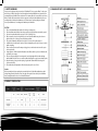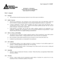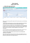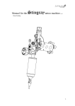
1
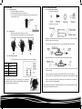
PF Series
Installation & Operating Manual
PM13500PF
PM13500UF - UV Option
Warning!
Never leave children unsupervised around water.
Table of Contents
LIMITED WARRANTY
ADG Global Supply Pty Ltd will repair or replace any unit found to be defective within two years of original purchase. Cutting
or altering cord removing or defacing product labels voids any warranty consideration. For warranty repair return only the part
that is defective to your local dealer. Please include a dated proof of purchase. Damages or injuries resulting from negligence,
shipping, handling, improper installation, maintenance or misuse of the product are not covered by warranty. This warranty
gives you specific legal rights which vary from state to state.
To validate this warranty keep your proof of purchase (copy of sales receipt).
1.
2.
3.
4.
5.
6.
7.
8.
9.
10.
Safety guidelines
Product Specification
Exploded Drawing
Installation
Open the lid
Filter Media Placement
Inlet/Outlet Installation
Start- up method
Backwash Method
UV light Usage and Replacement (PM13500PUF)
3. DIAGRAM OF PARTS - EXPLODED DRAWING
1. SAFETY GUIDELINES
Foremost, we deeply appreciate your purchase of PondMate PF Series pressurised filter. For the correct
and safe usage of this product, please read thoroughly and understand fully this user’s manual before
operating the pressurised filter. Please understand our company will not be responsible for any disease,
wither, or death of fish, water plants, and other organisms caused by incidents attributed to incorrect
operating method or inadequate maintenance. In effort to improve product quality, we will make
necessary modifications to our existing model without prior notification.
CAUTION
1.
2.
3.
4.
Please check immediately after purchase for damage or missing parts
Please install the unit in stable position above water level or bury the filter canister in the ground
Best used in ponds with volume capacity of 13,500L (3,600Gal) or less.
Before operation, please check again for proper connection. After initial start, please observe a
while to make sure no leakage or unusual working condition.
5. This product is limited to artificial pond only, please do not use for any other purposes
6. Install the unit on levelled surface and never place it horizontally or place object on top or encircle
it with something.
7. Electric cord has been treated for waterproofing, please use with caution since it won’t be repair
able or replaceable.
8. Inappropriate use of filter materials will result in reduced flow, therefore, please use filter materials
provided by our company.
9. Please use adequate length of connecting tube. Overly long length will lead to tube bending
which inhabits flow. Please do not connect two filter units together or apply one to multiple ponds.
10. Regular cleaning of every part and replacing of gasket and sealant will reduce breakage and
increase product life.
11. The maximum head height (Qmax) of the selected pump can’t be over of 5.0m.
Reminder
Before operating hand, please unplug the power with dry hands. Use this filter within the specified
voltage rating parameter. Keep the power cord, plug, and receptacle clean and dry. Prevent children
from operating the unit. Do not use near flammable material.
2. PRODUCT SPECIFICATION
(mm)
4. INSTALLATION
4. INSTALLATION (CONTINUED)
4.4 Inlet/Outlet Tube Installation
1. Included Assembly parts
4.1 Installation Position
1. Must be installed above water level.
2. Must keep bucket levelled, not easy to tilt over.
3. For ease of operation and space saving, the product is recommended to be
buried in the ground.
2. Required Purchase parts
4.2 Opening of lid
1. Rotate to open the knob of the pressure releaser.
2. Remove the metal hoop between the top cover and the bucket.
3. Lift up the top cover by grabbing the inlet and waste outlet tube.
A)
Wrap the waste outlet thread with sealing tape, then screw in the waste outlet assembly with
ball valve. Tighten to prevent leakage.
B)
Place the gasket onto inlet/outlet, then screw on to tighten the inlet/outlet assembly
C)
Plug in three different hoses onto the inlet/outlet and waste outlet assembly
D)
The hose connecting to the inlet port marked “PUMP” needs to have the other end connected
to the water pump.
E)
The hose connecting to the outlet port marked “WORK” needs to have the other end
connected to the pond, so that the filtered water can return to the pond, waterfall, or fountain.
F)
The hose connecting to the ball valve assembly needs to have the other end connected to a
sump or a sprayer for watering the plants.
4.3 Filter media placement
1. Please follow the placement order shown below to ensure best filtering.
Layer 1
Black filter
Layer 2
Blue filter
Layer 3
Blue filter
Layer 4
Base plate Assembly
Layer 5
Bio-balls (60pcs)
2. After completing above step, please close the top cover assembly and
tighten with metal hoop. Please have adult handle the mental hoop to
prevent accidental nipping of the hand.
Note: If the user will only use the largest diameter on the Inlet/Outlet assembly for hose connection, then the two smaller diameter sections can
be sawed off for guaranteed flow and increased filter efficiency.
5. START-UP
5.1 Position the ball valve in closed condition
5.2 Make sure the water pump is submerged in pond with great connection. Ensure that
the hose connection is not bending.
6. BACK-WASH (CONTINUED)
6.4 Rotate the handle 120 degrees to the “CLEAN” position.
6.5 Make sure one end of the hose is connected to the ball valve and the other end
connected to sump, then turn on the water pump to begin backwash.
5.3 Rotate the handle so that the arrow will point to “WORK”
6.6 After water coming out of the waste outlet turns clean, shut off the water pump.
Rotate the handle back to “Work” position and turn on the water pump back on to
begin filtering process.
6.7 Since the waste will not be completely cleaned during the backwash, it is
recommended to take out the filter media for thorough cleaning after performing
three times of backwash.
5.4 Make sure the power plug is dry before plugging into receptacle that is positioned in
a safe position without being rained on.
5.5 After start-up, make sure all parts are operating properly without leakage.
5.6 For PM13500PUF, open the transparent cover to turn on the UV light, observe
whether LED lights up which would indicate if UV light is functioning.
6. BACK-WASH
6.1 When the red rubber inside the annunciator rises to viewable level through the
transparent cover, there is too much waste accumulated inside the bucket and
backwash is needed.
6.2 Turn off the water pump, make sure UV light is in “off ” position (for PM13500PUF)
7. UV LIGHT USAGE & REPLACEMENT
7.1 UV Light Usage
A) Open up the transparent cover on the top lid.
B) Turn on by pressing “-” downward, if the LED indicator lights up then the UV Light
is working.
C) Turn off by pressing “o” downward, if the LED indicator light is off, then the UV
Light has stopped working.
D) Close off the transparent cover.
Note:
A. If the LED indicator does not light up after pressing “-” , then UV light might need replacing.
B. The working hour of the UV light can be determined by pond capacity & breeding type.
7.2 UV Light Bulb Replacement
A) Open up top lid assembly; take out the middle
water guiding tube assembly.
B) Gently pull out the quarts glass sleeve
6.3 Rotate the handle 120 degrees to the “CLEAN” position.
C) Pull out the failed UV bulb, and then take off the bulb support frame. Replace
with a new bulb by attaching the support frame; insert it into the receptacle, and
then slide the quarts glass sleeve back on.