1
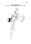
Manual for the Stingray tattoo machine rev.1 Patent Pending 1 Introduction We are proud to present the Stingray tattoo machine. Designed with the tattoo artist in focus and manufactured with the highest quality materials and components available. Description The Stingray is a state of the art rotary based Desmodromic cam tattoo machine with features that gives it several advantages compared to other tattoo machine types. The most important advantage is the new Patent Pending Desmodromic roller cam system which gives the unique ability to produce a defined needle motion with full control. Unlike any normal rotary machine or swash drive that has a fixed eccentric motion the Desmodromic cam can produce a 100% controlled linear motion with variable speeds at certain angles of the motor revolution with the motor spinning at a constant rpm. The Stingrays Desmodromic cam system enables to create a motion that is perfect for lining and color packing like a tuned coil machine but with greater precision and consistency. Not only does the system allow you to change to different stroke lengths ( other cams and stroke lengths than standard 3.5mm may be available later on ) but also the ability to totally change the characteristics and behavior of the machine and the needle speed by changing to different cams. Changing the cam is very easy and takes only a few minutes. Benefits Besides the obvious that it is light and has a comfortable sound the greatest benefit with the Stingray is that it makes it easier to penetrate difficult areas of the body and loose skin, put the pigment in to the skin more efficiently and cause less damage and better healing. Like the Dragonfly the Stingray have been tested and developed for over two years by engineers and several professional tattoo artists which means that you can look forward to the reliable and satisfactory performance of the Stingray for years to come. To ensure safety and obtain maximum service life from the machine it is essential that users read and understand this manual. Check out www.Inkmachines.com for more info and news. 2 Safety The Stingray is designed and developed solely for tattooing of humans by professional tattoo artists. Do not under any circumstances use for other purposes. Inkmachines only provide products for professional tattoo artists and may only be used by professionals with knowledge about diseases and how to maintain a clean working environment and sterile equipment. Work safe! Always use sterile tubes, grips, tips and needles. Always use rubber gloves. Use plastic bags and wraps for tattoo equipment around the machine and the power cord. Always keep your machines clean! Before and after every use you should: remove any oil or dirt and wipe the machine clean with alcohol or equivalent disinfectant. The manufacturer does not have responsibility for any kind of material damage, person damage or infection caused by negligence or misuse of the machine or the components attached to the machine. The manufacturer does not have responsibility for contamination or infection of humans or animals. 3 Maintenance instructions Lubrication Use the oil that were supplied with the machine and follow these steps to lubricate every 50 hours of use. Only use the oil provided with the machine, other oils may reduce lifetime of the machine and / or clog. 1. Remove grip and needle. 2. Remove the cap and use the releaser to release the piston assembly while pushing the piston assembly down to the bottom of its stroke. Lube with a small amount of oil in the corners between the piston and the frame . Put the cap back in place. 3. Apply oil just above the needlebar pin in the oval hole. 4. Apply oil on the bearings of the needlebar retainer and roll the bearings a few times back and forward to let the oil run into the bearings. 5. Apply oil between the bearing rod and the shaft support . No oil is required on the cam bearings. 6. Run the machine around 9 volts for about a minute and clean it when done. Lash adjustment The lash or play between the Cam bearings and the Cam needs to be checked every 100 hours of use and adjusted if needed. Too much play between the cam bearings and the cam will cause excessive noise and increased wear on the cam. 1. 2. 3. 4. Remove grip and needle. Loosen the rod screw just enough to make rod assembly movable. Remove the cap Push the piston assembly and the rod assembly together against the cam so that both cam bearings has contact with the cam and then tighten the rod screw 5. Make sure that the lash is ok by pushing down and releasing the piston assembly while looking at the cam and the upper cam bearing. The play should be 0 – 0.2mm. Use a 0.2mm thick gauge if possible. It should not fit between the cam and the upper cam bearing. 6. Run the machine around 9 volts to make sure everything runs smoothly. 4 Changing cams 1. 2. 3. 4. 5. 6. 7. 8. 9. Remove grip and needle. Remove the cap Remove the shaft support screws and the rod screw . Remove the shaft support and the rod assembly . Rotate the cam and locate the cam screw with a 0.9mm Allen key through the hole in the frame . Loosen the cam screw and remove the cam . Clean the parts and the frame and align the flat part of the motor shaft towards the hole in the frame. Mount the new cam of choice with the cam screw downwards so that the cam screw and the flat part of the motor shaft align with each other and with the hole in the frame . Make sure that the cam is all the way down against the motor and tighten the cam screw . Put the rod assembly and the shaft support in place and tighten the shaft support screws . The shaft support must be oriented with the clearance groove downwards or the rod assembly won´t fit properly. Preform the lash adjustment. Service Tools and spare parts are available on www.inkmachines.com in the spare parts section if you want to do service work yourself. You can also send machines to our service technicians for a full service. For more information go to www.inkmachines.com Warranty This product includes a 12 month warranty from the date of purchase. The warranty applies to factory faults and not to wear of any components caused by normal or abnormal use. The warranty is void if: 1. Input Voltage above 13 volts has been applied to the machine. 2. Machine or any of its components have been autoclaved or cleaned in an ultrasonic cleaner. 3. Components have been damaged by misuse or carelessness. 4. Components have been manipulated. 5 Getting started 1. Disconnect the machine from the power supply. 2. Attach a new quality rubber nipple or grommet to the needlebar pin . The nipple or grommet should have a tight fit with the needlebar loop. 3. Open the retainer to make clearance for the needlebar and tube by adjusting the retainer screw . 4. Bend the needlebar to a slight arc shape and / or make a bend just at the soldering to compensate the pressure from the needlebar retainer. This enables the needles to work straighter, prevent it from wobbling and making it more stable in the tip. 5. Insert the needle carefully into the tube without damaging the needle tips. 6. Insert the tube / needle assembly trough the tube vice clamp and tighten the vice lightly. Attach the needlebar loop to the nipple. 7. Move the needlebar pin and the attached needlebar down to the bottom of its stroke by pressing the needlebar pin downwards, if the needlebar pin won’t move down push the releaser to release it. 8. Inspect and adjust the protrusion and alignment of the needle and tip by moving the grip and tube to the desired location. Tighten the tube vice firmly when done . 9. Adjust the needlebar retainer by turning the retainer screw until the retainer o-ring makes contact with the needlebar. Don’t tighten more than necessary to keep the needle stable in the tip. If the needlebar don’t align properly with the retainer o-ring, adjust / bend the needlebar so that it aligns. 10. Connect the machine to a power supply ( max 13 volts DC ) either with a RCA cable to the RCA contact or a clipcord to the clipcord binding posts , if you choose to use a clipcord make sure to connect positive to + and negative to – marked on the machine next to the bindingposts. The motor should turn clockwise when looking at the front. 11. Run the machine between 9-12 volts depending on needle size and friction, fine adjust the needlebar retainer until the needle feels stable in the tip and make sure that everything runs smoothly without excessive friction or noise. 12. Run the machine and adjust the needle suspension by feeling the needlebar pin and nipple with your finger and by turning the cap to get the desired hitting, clockwise = harder, counter clockwise = softer. When the cap is turned clockwise to the bottom the needlebar pin will be locked with the piston . This position will give the hardest hitting. When the cap is turned counter clockwise the stroke will be increasingly softer until the limit is reached. When the limit is reached the adjustment screw will make contact with the cap from the inside and produce noise, turn the cap clockwise until the adjustment screw clears the cap and the noise stops. If you turn the cap too far and the cap should come off during this operation, screw down the adjustment screw two turns and reattach the cap by pushing it until it clicks into place. 13. Encapsulate the machine and cord with plastic bags and wrappings for tattoo equipment. 14. Typical start value would be around 9 volts. The adjustment is normally set to soft for lining and medium to hard for filling / packing color. These are just start values and are very much individual. You may find other settings to suit you better depending on your technique, equipment etc. 6 Specifications Input voltage Power connections Rpm range Stitches / sec Stroke length Suspension stroke Max. tube diam Ø Max. needle size Weight Dimensions LxBxH 0 - 13 volt DC (max. 13 volt DC) RCA or clipcord (max. clipcord end diam Ø1,6 mm) 0 - 8 000 rpm / min 0 - 130 / sec 2.6 - 3.5 depending on cam used ( 3.5mm standard ) 0 - 2 mm Ø8 mm 50 magnum 90 grams 95 x 21 x 75 mm 7 Part names Note: Parts without numbers are not included in the purchase. 8 9