1
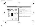
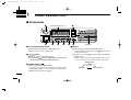
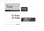
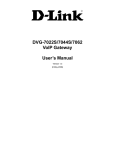
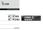
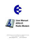
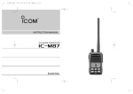
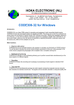
!IC-400PRO.qxd
03.6.16 2:27 PM
Page a (1,1)
INSTRUCTION MANUAL
UHF TRANSCEIVER
i400PRO
!IC-400PRO.qxd
03.6.16 2:27 PM
Page i (1,1)
IMPORTANT
PRECAUTION
READ ALL INSTRUCTIONS carefully and com-
RWARNING! NEVER connect the transceiver to an
AC outlet. This may pose a fire hazard or result in an electric
shock.
pletely before using the transceiver.
SAVE THIS INSTRUCTION MANUAL — This
instruction manual contains important operating instructions
for the IC-400PRO UHF TRANSCEIVER.
EXPLICIT DEFINITIONS
WORD
DEFINITION
Personal injury, fire hazard or electric shock
RWARNING may occur.
CAUTION
NOTE
Equipment damage may occur.
If disregarded, inconvenience only. No risk
of personal injury, fire or electric shock.
RWARNING! NEVER operate the transceiver while
driving a vehicle. Safe driving requires your full attention—
anything less may result in an accident.
NEVER connect the transceiver to a power source of more
than 16 V DC. This will damage the transceiver.
NEVER cut the DC power cable between the DC plug and
fuse holder. If an incorrect connection is made after cutting,
the transceiver might be damaged.
NEVER place the transceiver where normal operation of
the vehicle may be hindered or where it could cause bodily
injury.
NEVER allow children to play with any radio equipment
containing a transmitter.
NEVER expose the transceiver to rain, snow or any liquids.
The transceiver may be damaged.
NEVER operate or touch the transceiver with wet hands.
Icom, Icom Inc. and the
logo are registered trademarks of Icom
Incorporated (Japan) in the United states, the United Kingdom, Germany,
France, Spain, Russia and/or other countries.
SmarTrunk II™ is a trademark of the SmarTrunk Systems, Inc.
i
This may result in an electric shock or damage the transceiver.
!IC-400PRO.qxd
03.6.16 2:27 PM
Page ii (1,1)
DO NOT push the PTT when not actually desiring to trans-
BE CAREFUL! The transceiver will become hot when
mit.
operating continuously for long periods.
DO NOT use or place the transceiver in areas with temperatures below –10°C or above +60°C, or in areas subject to
direct sunlight, such as the dashboard.
This device complies with Standard
Australia Specification No. AS/NZS43651996 and AS4295-1995.
AVOID operating the transceiver without running the vehicle’s engine. When the transceiver’s power is ON and your
vehicle’s engine is OFF, the vehicle’s battery will soon
become exhausted.
AVOID placing the transceiver in excessively dusty environments.
AVOID
placing the transceiver against walls. This will
obstruct heat dissipation.
AVOID setting the transceiver in a place without adequate
ventilation. Heat dissipation may be affected, and the transceiver may be damaged.
AVOID the use of chemical agents such as benzine or
alcohol when cleaning, as they damage the transceiver surfaces.
USE the specified microphone only (supplied or optional).
Other microphones have different pin assignments and may
damage the transceiver.
ii
!IC-400PRO.qxd
03.6.16 2:27 PM
Page iii (1,1)
TABLE OF CONTENTS
IMPORTANT ........................................................................ i
EXPLICIT DEFINITIONS ..................................................... i
PRECAUTION ..................................................................... i
TABLE OF CONTENTS ...................................................... iii
SUPPLIED ACCESSORIES ............................................... iv
1 PANEL DESCRIPTION ............................................... 1–4
■ Front panel ................................................................... 1
■ Function display ........................................................... 4
2 BASIC OPERATION .................................................... 5–6
■ Turning power ON ........................................................ 5
■ Channel selection ......................................................... 5
■ Receiving and transmitting ........................................... 6
3 REPEATER OPERATION ............................................... 7
■ Repeater operation.........................................................7
■ Accessing a repeater......................................................7
4 SCAN OPERATION ................................................... 8–14
■ Scan types......................................................................8
■ Scanning preparation .....................................................9
■ Open scan ....................................................................11
■ Group and priority scans ..............................................12
■ Repeater search scan ..................................................13
5 GROUP MODE OPERATION .................................. 15–16
■ Group mode (CTCSS)..................................................15
6 SELCALL OPERATION .......................................... 17–21
■ General.........................................................................17
■ Calling operation ..........................................................17
■ When receiving a call ...................................................20
■ Setting the silent stand-by condition.............................21
iii
7 OTHER FUNCTIONS .............................................. 22–33
■ Smart-Ring and ATS (Automatic Transponder System) .....22
■ Voice scrambler function ..............................................23
■ DTMF transmission ......................................................24
■ Channel lock function ...................................................24
■ RX frequency setting ....................................................25
■ Wide/Narrow function ...................................................26
■ Set mode ......................................................................27
8 PROGRAMMABLE FUNCTION KEYS ................... 34–36
9 CONNECTION AND MAINTENANCE .................... 37–40
■ Rear panel and connection ........................................ 37
■ Mounting the transceiver ............................................. 38
■ Optional UT-108 installation ....................................... 39
■ Optional UT-109 or UT-110 installation ...................... 39
■ Optional OPC-617 installation ..................................... 40
■ Antenna ....................................................................... 40
■ Fuse replacement ....................................................... 40
■ Cleaning ..................................................................... 40
10 SPECIFICATIONS ....................................................... 41
11 OPTIONS ..................................................................... 42
!IC-400PRO.qxd
03.6.16 2:27 PM
Page iv (1,1)
SUPPLIED ACCESSORIES
q Microphone .................................................................. 1
q
w
e
w Microphone hanger and screw set .......................... 1 set
e Microphone hanger cable .............................................. 1
IC
OM
r DC power cable (OPC-1194) ..........................................1
t Function name stickers* (KEY STICKER) ......................1
y Mounting bracket ........................................................... 1
r
y
t
u Bracket bolts ................................................................. 4
i Mounting screws (M5×12) ............................................. 4
o Self-tapping screws (M5×20) ......................................... 4
KEY-STICKER
!0 Flat washers .................................................................. 4
!1 Spring washers ............................................................. 4
!2 Nuts ............................................................................... 4
u
!0
i
!1
o
!2
*Function name stickers
Function of keys can be changed. Stickers are supplied for
easy identification.
iv
!IC-400PRO.qxd
03.6.16 2:27 PM
1
Page 1 (1,1)
PANEL DESCRIPTION
■ Front panel
q
i
w
Function Display (p. 4)
u
y
t
q AF VOLUME CONTROL KNOB
Rotate the knob to adjust the audio output level.
• Minimum audio level is pre-programmed.
w [ ]/[ ] KEYS*
➥ Push to select an operating channel.
➥ After pushing [O], push to toggle between CB bank and
Private bank (user programmable channels).
r
e
Speaker
r [O] KEY*
➥ Push to enter channel bank selection mode.
• In channel bank selection mode, push [
desired channel bank.
]/[
➥ Push for 1 sec. to toggle Function mode, Set mode or
Normal mode.
• Returns to the Normal mode automatically after 30 sec. when
no key operations are performed in Function or Set mode.
Normal mode
e POWER SWITCH [
]
Push to turn the power ON and OFF.
• The Automatic scan start function and the password prompt are
available at power ON as optional settings. (The optional CS400PRO CLONING SOFTWARE is required.)
1
] to select the
Push [O]
for 1 sec.
Set mode
Function mode
!IC-400PRO.qxd
03.6.16 2:27 PM
Page 2 (1,1)
PANEL DESCRIPTION
1
t [DUP] KEY*
➥N Push to toggle the transmit frequency mode between
duplex and simplex. (CB channel 1 to 8 only)
u [MONI] KEY*
➥N Activates the following functions on each channel
independently:
• Duplex: The set TX frequency is used for the transmission.
• Simplex: The set RX frequency is used for the transmission.
• Push and hold the key to release the mute to the channel
(audio is emitted; ‘Audible’ condition).
-“
” appears.
• During “
” appears, push the key to mute the channel
(sets to ‘Inaudible’).
➥N Push and hold to set the selected channel to priority
or normal.
• Priority channel is used for both group and priority scans.
➥F Push to toggle the 5tone mute activity between CONT
(Continuous Tone) and SGL (Single Tone).
• CONT: SelCall mute is released.
• SGL: SelCall mute is activated. In this case, [PTT] switch
action is inhibited while SelCall mute is activated.
y [SCN] KEY*
➥N Push to start or stop the scan.
➥N Push and hold to enter the scan type selection mode.
• Push [ ]/[ ] to select the desired scan type.
• Push [SCN] to set the channel as a tag channel.
- “S” appears for tag channels.
➥F Push to recall the received ID code.
• Push [
]/[
] to select the record.
➥N : Stands for Normal mode operation.
➥F : Stands for Function mode operation.
1
NOTE: The unmute condition (‘Audible’ condition)
may automatically return to the mute condition
(‘Inaudible’ condition) after a specified time period
depending on the pre-setting.
➥F Push to transmit the SelCall code on the selected
channel.
➥F Push and hold to enter the SelCall code/code number
selection mode (p. 17).
• Push [
]/[
] to select the desired code/code number.
*Information
Up to two desired functions, one each for Normal and
Function mode, can be re-assigned to [ ], [ ], [O],
[DUP], [SCN] and [MONI] keys with the optional CS400PRO CLONING SOFTWARE. (p. 34)
The default setting is used in this instruction manual, for
description.
2
!IC-400PRO.qxd
03.6.16 2:27 PM
1
Page 3 (1,1)
PANEL DESCRIPTION
Key flow chart for the default setting
Push [
] to turn power ON.
Normal mode
: [CH Up]
: [Scan Start/Stop]
: [CH Down]
: [Moni(Audi)]
: [Dup/Pri]
: [Bank/Func]
Push [O] for 1 sec.
Function mode
: [CH Up]
: [ID-MR Select]
: [CH Down]
: [Call]
: [CONT/SGL]
: [Bank/Func]
Push [O] for 1 sec.
Set mode
/ : Set the desired level/mode.
: Change the individual setting.
: Change the common setting.
: Turn the function ON and OFF.
: Push to enter channel bank selection mode.
Push for 1 sec. to enter Normal mode.
3
i MICROPHONE CONNECTOR
Connect the supplied microphone or optional DTMF microphone.
NEVER connect non-specified microphones. The pin
assignments may be different and the transceiver may
be damaged.
D MICROPHONE
The supplied microphone has a PTT switch and a hanger
hook.
• The following functions are available when the microphone is on or
off hook:
(The optional CS-400PRO CLONING SOFTWARE is required.)
- Automatic scan start when on hook.
- Automatic priority channel selection when off hook.
- Sets to ‘Inaudible’ condition (mute condition) when on hook.
- Sets to ‘Audible’ condition (unmute condition) when off hook.
!IC-400PRO.qxd
03.6.16 2:27 PM
Page 4 (1,1)
PANEL DESCRIPTION
1
■ Function display
q w
e
r
t
y
1
u
u SCRAMBLER INDICATOR
Appears when the scrambler function is activated. (Optional
UT-109 (#02)/UT-110 (#02) SCRAMBLER UNIT is required.)
i o
!0
!1
q TRANSMIT INDICATOR
Appears while transmitting.
w BUSY INDICATOR
Appears while receiving a signal or when the squelch is
open.
e SIGNAL STRENGTH METER
Indicates relative receive signal strength level.
r LOW POWER INDICATOR
Appears when low output power is selected.
[High/Low] must be assigned to the desired programmable key using the optional CS-400PRO CLONING
SOFTWARE when change the output power.
t SQUELCH INDICATOR
Appears when the channel is in ‘Audible’ condition
(SelCall/CTCSS mute is released).
y DUPLEX INDICATOR
Appears when the duplex operation is selected.
i SELCALL/5TONE INDICATOR
Appears when the specified Selcall/5-tone is received.
o SCAN CHANNEL INDICATOR
Appears when the selected memory channel is specified
as a scan channel.
!0 ALPHANUMERIC DISPLAY
Displays the operating channel number, channel names,
Set mode contents, DTMF numbers, etc.
!1 UNDER BAR INDICATOR
➥ Shows the channel mute condition (‘Inaudible’ condition) as below.
➥ The left under bar blinks in Function mode, and lights in
Set mode.
➥ Appears in Set mode when the key under the indicator
can be activated.
The channel is in CTCSS mute condition.
The channel is in SelCall mute condition.
The channel is in both CTCSS/SelCall mute
condition.
During “ ” appears, the channel is ‘Audible’ condition
even if the channel is in mute condition.
4
!IC-400PRO.qxd
03.6.16 2:27 PM
2
Page 5 (1,1)
BASIC OPERATION
■ Turning power ON
■ Channel selection
➥ Push [
➥ Push [
] to turn the power ON.
]/[
] to select the desired operating channel.
• While pushing and holding [ ] or [ ], the displayed channel
changes continuously until channel number “01” appears.
• When displayed channel stops at channel number “01”, beeps
are emitted.
Push [ ] or [ ]
Push [ ]
About the password prompt:
If the transceiver is programmed for a start up passcode,
enter the specified 4-digit code.
(The optional CS-400PRO CLONING SOFTWARE is required.)
D Private channel selection
• The keys in the table below can be used for password input:
• The transceiver detects numbers in the same block as identical.
Therefore “01234” and “56789” are the same.
q Push [O] (Bank/Func) to enter the channel bank selection
mode. Then select the desired bank with [ ]/[ ]. Push
[O] (Bank/Func) again to set the bank.
KEY
NUMBER
Push [O]
0
5
1
6
2
7
3
8
4
9
When the “PASSWORD” indication does not clear after
entering 4 digit code, the enter code number is incorrect. In
this case, turn the power off and start over.
5
w Push [ ]/[
sequence.
] to select the desired operating channel in
NOTE: The selected channel is retained even when the
transceiver is turned off.
!IC-400PRO.qxd
03.6.16 2:27 PM
Page 6 (1,1)
BASIC OPERATION
2
■ Receiving and transmitting
RECEIVING:
q Push [
] to turn the power ON.
w Select the desired operating channel. (p. 5)
e While receiving a signal, adjust the audio output level to a
comfortable listening level.
TRANSMITTING:
q While pushing and holding [PTT], speak into the microphone at your normal voice level.
w Release [PTT] to receive.
D Transmitting notes
2
• Time-out timer
After continuous transmission for a pre-programmed period,
the time-out timer is activated causing the transceiver to stop
transmitting and automatically select receive.
NOTE: Transmission is inhibited when the channel is in 5
tone mute condition (‘Inaudible’ condition), or receive only
channel is selected.
IMPORTANT!: To maximize the readability of your signal;
➥ After pushing [PTT], pause briefly.
➥ Hold the microphone 2 to 5 cm from your mouth, then
speak into the microphone at a normal voice level.
6
!IC-400PRO.qxd
03.6.16 2:27 PM
3
Page 7 (1,1)
REPEATER OPERATION
■ Repeater operation
■ Accessing a repeater
Repeaters allow you to extend the operational range of your
radio.
A repeater amplifies received signals and re-transmits them
on a different channel, allowing you to communicate over
greater distances with improved reliability. When using a
repeater, the transmit channel is shifted from the receive
channel by 30 channels. You can search the accessible
repeater in your local area using the Repeater search scan
function (p. 13).
Normally, a repeater has independent frequencies for receive
and transmit.
Repeater example;
Receives the channel 31 signal and
the detected audio signals are transmitted on channel 1 simultaneously.
Ch 1
Ch 31
Station A:
Tx: Channel 31
Rx: Channel 1
Ch 31
Ch 1
Station B:
Tx: Channel 31
Rx: Channel 1
q Push [ ]/[ ] to select the desired channel from 1 to 8
(repeater output channel).
w Push [DUP] (Dup/Pri) to set duplex.
• “ ” appears.
• The duplex setting is only available on channels 1 to 8.
e While pushing and holding [PTT], speak into the microphone at your normal voice level.
• The displayed channel automatically changes to the transmit
channel (repeater input channel), and “ ” appears.
r Release [PTT] to receive.
t To cancel the duplex setting, push [DUP] (Dup/Pri).
7
!IC-400PRO.qxd
03.6.16 2:27 PM
Page 8 (1,1)
4
SCAN OPERATION
■ Scan types
The transceiver has 4 scan types, tag function and 4 resume
conditions providing scanning versatility.
Tag channels are independently set for open, group and priority scans. Initially, all channels may be set as tag channels
for all scans.
IMPORTANT!:
A microphone should be on hook to start scanning.
3
4
REPEATER SEARCH SCAN
OPEN SCAN
ch 1
ch 2
ch 3
Scan cancel
ch 40
ch 1
RX only
ch 2
RX only
ch 8
RX only
ch 4
ch 39
ch 6
TX on ch 38
RX on ch 8
ch 5
TX on ch 31
RX on ch 1
Repeatedly scans all tag channels in sequence.
TX on ch 34
RX on ch 4
GROUP OR PRIORITY
SCAN
TX on ch 32
RX on ch 2
Scans all repeater channels (1 to 8) in sequence.
If there are no busy channels after scanning channels 1
to 8 (RX only), it begins scanning from channel 1 again,
then the transceiver transmits a signal to search for a repeater while the scanning.
ch 8
Priority
channel
ch 12
TX on ch 33
RX on ch 3
ch 26
Repeatedly watches a priority channel while scanning
only specified tag channels.
8
!IC-400PRO.qxd
03.6.16 2:27 PM
4
Page 9 (1,1)
SCAN OPERATION
■ Scanning preparation
IC-400PRO scans all tagged channels, and can be selected
so the scan resume condition is a pause or timer scan.
Therefore, these items must be set before starting a scan
(except the repeater search scan). These items must be set
for each scan type (open, group and priority) independently.
r Push [SCN] (Scan Start/Stop) to select the tag setting ON
and OFF.
• “S” appears when the tag setting ON (The channel is set as a
scan channel).
Push [SCN]
(Scan Start/Stop)
Appears for
the channels
to be scanned
D Setting scan tag
q Select the desired channel. (p. 5)
w Push [SCN] (Scan Start/Stop) for 1 sec. to enter the scan
type selection mode.
t Push [SCN] (Scan Start/Stop) for 1 sec. to return to
Normal mode.
Previously selected scan type
is displayed.
Push [SCN] for 1 sec.
e Push [
]/[
] to select the desired scan type.
• Open, group, priority and repeater search scans are available.
Push [
] or [
]
Open scan
9
Open scan setting
To speed up scanning:
For open scan, cancel the tag channel setting to skip undesired channels such as usually busy channels.
For group scan, set only often-used channels as tag channels.
All memory channels may be set as tag channels by
default.
!IC-400PRO.qxd
03.6.16 2:27 PM
Page 10 (1,1)
SCAN OPERATION
D Setting scan resume condition
q Push [O] (Bank/Func) for 1 sec. to enter Function mode.
w Push [O] (Bank/Func) for 1 sec. again to enter Set mode.
[
t Push [
tion.
- “T-5”
- “T-10”
- “T-15”
- “P-5”
Push [O] for 1 sec.
Bank*
4
]/[
] to select the desired scan resume condi-
: Scan pauses for 5 sec. then resumes.
: Scan pauses for 10 sec. then resumes.
: Scan pauses for 15 sec. then resumes.
: Scan pauses until the signal disappears, then resumes
5 sec. after the signal disappears.
T-5 setting
T-10 setting
T-15 setting
P-5 setting
4
Channel*
*The bank and channel number
are continuously displayed after entering set mode.
The keys under these indicators can be activated.
e Push [SCN] for 1 sec. to enter the common setting for the
transceiver.
r Push [SCN] several times until “SST” appears.
Push [SCN]
y Push [SCN] for 1 sec., then push [O] for 1 sec. to return to
Normal mode.
SST appears
10
!IC-400PRO.qxd
03.6.16 2:27 PM
4
Page 11 (1,1)
SCAN OPERATION
■ Open scan
Open scan searches for being transmitted signals automatically and makes it easier to locate new stations for contact or
listening purposes.
IMPORTANT!:
• A microphone should be on hook to start scanning.
• During open scan, transmission is inhibited except on a
busy channel.
q Push [SCN] (Scan Start/Stop) for 1 sec. to enter the scan
type selection mode.
Previously selected scan type
is displayed.
Push [SCN] for 1 sec.
w Push [
]/[
] to select the open scan.
Push [
] or [
]
Open scan
11
e Push [SCN] (Scan Start/Stop) for 1 sec. to return to
Normal mode.
- “OS” appears besides the channel number indication.
Open scan setting
r Push [SCN] (Scan Start/Stop) to start the open scan.
Start channel
t When receiving a signal, scan pauses and resumes
according to the selected scan resume condition. (p. 10)
y Push [SCN] (Scan Start/Stop) to cancel the scan.
!IC-400PRO.qxd
03.6.16 2:27 PM
Page 12 (1,1)
SCAN OPERATION
4
■ Group and priority scans
Group and priority scans repeatedly watch a priority channel
while scanning specified channels. This is useful when waiting for a call on the priority channel or several specified channels.
Group and priority scans behave differently when transmitting. Group scan can only transmit on a busy channel, and
priority scan can only transmit on a priority channel or start
channel.
r Select the priority channel if desired.
- Push [ ]/[ ] to select the desired channel.
- Push [DUP] (Dup/Pri) for 1 sec. to set the channel as a priority
channel.
Start channel
Group scan setting
IMPORTANT!:
A microphone should be on hook to start scanning.
q Push [SCN] (Scan Start/Stop) for 1 sec. to enter the scan
type selection mode.
w Push [ ]/[ ] to select the group or priority scan.
Push [
] or [
]
Group scan
4
Priority channel
Priority scan setting
t Push [SCN] (Scan Start/Stop) to start the scan.
Group scan
Priority scan
y When receiving a signal, the scan pauses and resumes
according to the selected scan resume condition. (p. 10)
u Push [SCN] (Scan Start/Stop) to cancel the scan.
Priority scan
e Push [SCN] (Scan Start/Stop) for 1 sec. to return to
Normal mode.
- “GS” or “PS” appears besides the channel number indication.
12
!IC-400PRO.qxd
03.6.16 2:27 PM
4
Page 13 (1,1)
SCAN OPERATION
■ Repeater search scan
The repeater search scan is not only searching for a signal
on the repeater channels, but also access a repeater by
transmitting automatically in sequence.
Thus the repeater search scan function searches an available
repeater in the area even if the repeater is not in use.
IMPORTANT!:
A microphone should be on hook to start scanning.
The repeater search scan detects a signal on the repeater
output, CH 1 to 8, only. Therefore, repeater availability cannot be guaranteed even the repeater scan is stopped,
because the scan will stop if any activity is detected. (The
scan is cancelled when receiving a signal, such as stations
communicating in simplex operation on a repeater output
channel.)
q Push [SCN] (Scan Start/Stop) for 1 sec. to enter the scan
type selection mode.
w Push [ ]/[ ] to select the repeater scan.
Push [
] or [
]
Repeater scan
13
e Push and hold [SCN] (Scan Start/Stop) to return to Normal
mode.
• “RS” appears when the repeater scan is selected.
Repeater search scan
r Push [SCN] (Scan Start/Stop) to start the repeater scan.
• See the flow as described at right for repeater search scan
details.
t When receiving a signal on the repeater channel, scan
stops.
• 3 high beeps sound when receiving a signal, and 3 low beeps
sound when no signal receiving.
y Push [SCN] (Scan Start/Stop) to cancel the scanning manually.
!IC-400PRO.qxd
03.6.16 2:27 PM
Page 14 (1,1)
SCAN OPERATION
4
D Repeater search scan flow
Scanning channel
is displayed.
4
Scan
Searches for signal on
repeater output signal.
Access to the repeater
automatically.
Wait for a signal from
the repeater.
When not reply signal is received.
Access to the next repeater automatically.
Scan is cancelled automatically.
14
!IC-400PRO.qxd
03.6.16 2:27 PM
5
Page 15 (1,1)
GROUP MODE OPERATION
■ Group mode
(CTCSS)
[
D Setting the CTCSS frequency
The IC-400PRO is equipped with 51 CTCSS frequencies for
group mode operation. The group mode operation provides
communication with silent stand-by since you will only receive
calls from group members using the same CTCSS frequency.
First of all, set the same CTCSS frequency for all group member’s transceivers.
To access the IC-40Jr or IC-4088S operating in Group mode
(including Smart-Ring function), the same CTCSS frequency
should be set. Select the CTCSS frequency matching the
group code that is set to the IC-40Jr or IC-4088S, referring to
the “Group code/frequency table” in the next page.
For example, when group code “01” is set to the IC-40Jr/IC4088S, select “67.0” as CTCSS frequency.
NOTE: Only the stations with the same CTCSS frequency
or matching the group code can be heard in group mode
operation.
To turn ON the group mode operation:
q Push [ ]/[ ] to select the desired channel.
w While in Function mode, push [O] (Bank/Func) for 1 sec.
to enter Set mode.
• Push [O] (Bank/Func) for 1 sec. to enter the transceiver into
Function mode.
• The bank and channel can be selected after entering Set mode.
Push [O] for 1 sec.
Bank*
Channel*
*The bank and channel number
are continuously displayed after entering set mode.
The keys under these indicators can be activated.
e Push [MONI] for 1 sec. to enter the individual setting.
r Push [MONI] several times until “CT” appears.
CT appears
[MONI]
t Push [
]/[
] to select the desired frequency.
• When “OFF” is displayed, push [DUP] to enables the tone frequency selection, in advance.
y Push [MONI] for 1 sec. to exit the individual setting, then
push [O] for 1 sec. to exit Set mode.
• The under bar indicator appears. (p. 4)
15
!IC-400PRO.qxd
03.6.16 2:27 PM
Page 16 (1,1)
GROUP MODE OPERATION
5
To cancel the group mode operation:
q While in Function mode, push [O] (Bank/Func) for 1 sec.
to enter Set mode.
✔ What is CTCSS (Continuous Tone Coded Squelch
System) GROUP MODE ?
• Push [O] (Bank/Func) for 1 sec. to enter the transceiver into
Function mode.
CTCSS (Continuous Tone Coded Squelch System)
GROUP MODE allows communication with silent stand by.
Only signals containing a specific CTCSS frequency can
open the squelch.
This conveniently eliminates unwanted audio and is useful
in group activities or security related activities where
unwanted output can be a problem. Note that CTCSS
group mode is not private—anyone can receive your calls.
w Push [MONI] for 1 sec. to enter the individual setting.
e Push [MONI] several times until “CT” appears.
r Push [DUP] to select “OFF” (group mode OFF).
Push [DUP]
t Push [MONI] for 1 sec. to exit the individual setting, then
push [O] for 1 sec. to exit Set mode.
• The under bar indicators disappear.
D Group code/frequency table
Code
01
----02
03
04
05
06
07
08
09
(unit: Hz)
Freq. Code Freq. Code Freq. Code Freq. Code Freq.
21 136.5 28 173.8 --- 206.5
67.0 10 94.8
22 141.3 --- 177.3 33 210.7
69.3 11 97.4
71.0 12 100.0 23 146.2 29 179.9 34 218.1
71.9 13 103.5 24 151.4 --- 183.5 35 225.7
74.4 14 107.2 25 156.7 30 186.2 --- 229.1
77.0 15 110.9 --- 159.8 --- 189.9 36 233.6
79.7 16 114.8 26 162.2 31 192.8 37 241.8
82.5 17 118.8 --- 165.5 --- 196.6 38 250.3
85.4 18 123.0 27 167.9 --- 199.5 --- 254.1
88.5 19 127.3 --- 171.3 32 203.5 --- OFF
91.5 20 131.8
5
The IC-400PRO is equipped with 51 CTCSS frequency for
CTCSS GROUP MODE use. Selecting a CTCSS frequency applies it to all 40 operating channels. To temporarily
hear all signals (including noise) push and hold [MONI]. Do
not use CTCSS GROUP MODE if you want to hear signals
on all channels.
: Stands for the recommended CTCSS frequency. In
case a frequency other than at left is used, sometimes
the squelch system may not performed correctly.
16
!IC-400PRO.qxd
03.6.16 2:27 PM
6
Page 17 (1,1)
SELCALL OPERATION
■ General
■ Calling operation
In addition to the group mode operation for silent stand-by,
the SelCall operation is available. SelCall is an abbreviation
for “Selective Calling”. In Group mode operation, there are 51
ways to make an individual call with CTCSS frequencies versus 100,000 ways to make an individual call with Selcall using
5tone.
SelCall allows you to selectively call another unit that is operating on the same channel.
SelCall can also call the entire group on that channel using
group call code.
D TX code channel selection
The caller station code/name, status message, Answer Back
function, automatic scan start function, etc. are available with
SelCall operation. A variety of functions are available depending on the setting with the CS-400PRO CLONING SOFTWARE.
See the help file for setting details.
The [MONI] (Call) key (in Function mode) enables you to
change the TX code channel with [ ]/[ ] keys.
TX code is transmit SelCall code. Max. 32 TX code channels can be pre-programmed into the IC-400PRO using
the optional CS-400PRO CLONING SOFTWARE.
To select a TX code channel:
q While in Function mode, push [MONI] (Call) for 1 sec. to
enter the TX code channel selection mode.
• Push [O] (Bank/Func) for 1 sec. to enter the transceiver into
Function mode.
Push [MONI] for 1 sec.
w Push [
]/[
Push [
17
The TX code or TX code
channel name (if programmed) is displayed.
] to select the desired TX code channel.
] or [
]
!IC-400PRO.qxd
03.6.16 2:27 PM
Page 18 (1,1)
SELCALL OPERATION
e Push [MONI] (Call) to set the TX code channel, and return
to Function mode.
Push [MONI]
r Push [MONI] (Call) to transmit the code on the selected
channel.
Appears while transmitting
Push [MONI]
✔ CONVENIENT!
• The TX code channel name can be assigned to the all 32
TX code channel via the optional CS-400PRO CLONING
SOFTWARE. The TX code channel name allows you to easy
to select the channel, find the channel user, and so on.
• The long tone function is useful and provides you to proper
individual or group call even through a repeater, or when the
calling station is in scanning operation. The long tone function can be activated in Set mode. (p. 30)
6
D TX code number edit
The [MONI] (Call) key (in Function mode) enables you to
change the TX code contents within the allowable digits.
The group call function works by allowing you to edit a special
‘group code’ into the last 2 digits position of the SelCall ID
code.
6
To edit a TX code:
q While in Function mode, push [MONI] (Call) for 1 sec. to
enter the TX code channel selection mode.
• Push [O] (Bank/Func) for 1 sec. to enter the transceiver into
Function mode.
• Push [ ]/[ ] to select the desired TX code channel, if desired.
w Push [MONI] (Call) for 1 sec. again to enter the TX code
edit mode.
Push [MONI] for 1 sec.
The first digit starts blinking
e Push [MONI] (Call) to select the desired digit to be edited.
• Editable digit blinks
Push [MONI]
18
!IC-400PRO.qxd
03.6.16 2:27 PM
6
Page 19 (1,1)
SELCALL OPERATION
r Push [
]/[
] to set the desired code.
• Select “❋” when group code is set.
Push [
] or [
o Push [MONI] (Call) to transmit the code on the selected
channel.
Appears while transmitting
]
Push [MONI]
t Push [MONI] (Call) to set the code and the editable digit
move to right automatically.
Push [MONI]
y Repeat step r and t to input all allowed digits.
u Push [MONI] (Call) to set the TX code.
Push [MONI]
i Push [MONI] (Call) to return to Function mode.
19
NOTE: The TX code editable digit can only be set/changed
with the optional CS-400PRO CLONING SOFTWARE.
!IC-400PRO.qxd
03.6.16 2:27 PM
Page 20 (1,1)
SELCALL OPERATION
6
■ When receiving a call
D Receiving an individual call
D Receiving a group call
When receiving an individual call (default setting);
When receiving a group call (default setting);
- “PiRo” beeps sound repeatedly for 10 sec.
- Transmits the answer back call with single tone for 2 sec.
- The received ID code is displayed and memorised into the transceiver.
- “ ” and “
” appear, and the channel turns ‘Audible’ condition
(mute is released)
- “PiPi” beep sounds.
- “GROUP” is displayed.
- “ ” blinks and “
” appears, and the channel turns ‘Audible’ condition (mute is released)
RX code is receiving SelCall code. Max. 8 RX code channels can be pre-programmed into the IC-400PRO using
the optional CS-400PRO CLONING SOFTWARE.
You can set the display condition when receiving a group call
with the CS-400PRO CLONING SOFTWARE. See the help file for
setting details.
6
Appears Blinks
You can set the transceiver condition when receiving an individual call using the CS-400PRO CLONING SOFTWARE. See the
help file for setting details.
Appear
D Answering a call
q When receiving a call (individual or group call), the indicators appear as at left/above.
w Push any key to return to the condition before receiving a
call.
Recall the memorised RX code:
q During in Function mode, push [SCN] (ID-MR Select) to
display the memorised RX code.
w Push [ ]/[ ] to select the desired RX code.
e Push [MONI] (Call) to transmit the code on the selected
channel.
•“
” still lights/blinks on the display.
e Then push [PTT] to communicate via the microphone with
the caller, if desired.
20
!IC-400PRO.qxd
03.6.16 2:27 PM
6
Page 21 (1,1)
SELCALL OPERATION
■ Setting the silent stand-by condition
The SelCall mute condition allows silent operation until you
are selcalled.
q While in Function mode, push [DUP] (CONT/SGL) and
select the single tone to activate the SelCall mute
(‘Inaudible’ condition).
• Push [O] (Bank/Func) for 1 sec. to enter the transceiver into
Function mode.
• When the single tone is selected, “SGL” is displayed briefly, and
the under bar appears as below.
Push [DUP]
e To monitor the channel;
Push [MONI] (Moni(Audi)) for 1 sec. to release the SelCall
mute (audio is emitted; ‘Audible’ condition).
•“
” appears.
Appears
Push [MONI] for 1 sec.
r To enable SelCall mute;
When “ ” appears, push the key to mute the channel
(sets to ‘Inaudible’).
Appears
•“
” disappears.
w Push [O] for 1 sec. to enter Set mode, and push for 1 sec.
again to return to Normal mode.
Push [MONI]
Push [O] for 1 sec.
21
Normal mode
NOTE: The unmute condition (‘Audible’ condition) may
automatically return to the mute condition (‘Inaudible’ condition) after a specified time period depending on the presetting.
!IC-400PRO.qxd
03.6.16 2:27 PM
Page 22 (1,1)
OTHER FUNCTIONS
■ Smart-Ring and ATS (Automatic Transponder System)
These functions have an answer back feature, and allows you
to confirmation of whether or not a call has reached the
receiving party even if the operator is temporarily away from
the transceiver. The Smart-Ring is for manual, and the ATS
is for automatic confirmation. Both functions are compatible
with the IC-40Jr and IC-4088S.
[ATS/S-ring] must be assigned to the desired programmable key using the optional CS-400PRO CLONING SOFTWARE.
7
KEY ASSIGNMENT
D ATS
➥ Push [ATS/S-ring] for 1 sec. to turn the function ON.
• The transceiver starts to send a searching signal every 60 sec.
• “ ” and “ ” appear on the display when the function is activated.
Appear
6
7
D Smart-Ring
q Set the same CTCSS frequency (or group code) for all of
the group transceivers. (See p. 15)
w Push [ATS/S-ring].
Appears while transmitting
Blinks when a group
member answers a call.
• A beep is emitted and “ ” appears on the display.
• When a member of a specific group answers a call, “ ” blinks.
• When no answer back is received, the transceiver emits short
faint beep tones.
e Push [PTT] to answer and to stop the flashing.
- When the transceiver receives an answer back signal, “ ” stays
on the display until the next search transmit.
- If no reply is received, “ ” blinks until the next search transmit.
NOTE:
• The setting at left is for the calling station only. A called
party automatically sends an answer back signal without
any presettings. All IC-400PRO’s operating on the same
operating channel will answer back to the call in the surroundings communications area.
• When the CTCSS frequency (or group code) is set to the
IC-400PRO, this function is available only for the same
frequency (code) setting.
NOTE: This function is available only when the called station has set the same CTCSS frequency (or group code)
and the same operating channel as you.
22
!IC-400PRO.qxd
03.6.16 2:27 PM
7
Page 23 (1,1)
OTHER FUNCTIONS
■ Voice scrambler function (optional UT-109/110 is required)
The voice scrambler function provides communication privacy. The optional UT-109/110 (#02) VOICE SCRAMBLER UNITS
provides high performance private communication between
stations with the same scrambling codes. The scrambler is
not compatible with the IC-4088S’s scrambler system.
• The scrambler group code is must be set in advance using
the optional CS-400PRO when the UT-110 is installed.
• ACA class licence inhibits using this function in channels
5, 11 and 35, or while accessing a repeater.
q Push [
]/[
[
e Push [MONI] for 1 sec. to enter the individual setting.
r Push [MONI] several times until “SCR” appears.
SCR appears
Push [MONI]
t Push [DUP] to turn the scrambler function ON.
] to select the desired channel.
• Except for the channels 5, 11 or 35.
w While in Function mode, push [O] (Bank/Func) for 1 sec.
to enter Set mode.
• Push [O] (Bank/Func) for 1 sec. to enter the transceiver into
Function mode.
Push [DUP]
t Push [
]/[
The scrambler
code appears
] to select the desired code.
• Available codes;
- UT-109 (Non-rolling type): 1 to 32
- UT-110 (Rolling type): 1 to 255
Push [
] or [
]
Push [O] for 1 sec.
Bank*
Channel*
*The bank and channel number
are continuously displayed after entering set mode.
23
The keys under these indicators can be activated.
y Push [MONI] for 1 sec. to exit the individual setting, then
push [O] for 1 sec. to exit Set mode.
!IC-400PRO.qxd
03.6.16 2:27 PM
Page 24 (1,1)
OTHER FUNCTIONS
■ DTMF
transmission
KEY ASSIGNMENT
Up to 8 DTMF (Dual Tone Multiple Frequency) code channels
are available for storage of often used DTMF codes of up to
24 digits and the automatic DTMF transmission function is
available without using the optional HM-100TN DTMF MICROPHONE.
DTMF signaling can be used for remote control via phone
patch system, etc.
[DTMF Autodial] must be assigned to the desired programmable key using the optional CS-400PRO CLONING
SOFTWARE.
■ Channel lock
function
7
KEY ASSIGNMENT
This function electronically locks [ ], [ ], [SCN] (Scan
Start/Stop)/(ID-MR Select), [MR-CH 1] to [MR-CH 4] and
[Hook Scan] keys (if assigned) to prevent accidental channel change.
[Ch Lock] must be assigned to the desired programmable
key using the optional CS-400PRO CLONING SOFTWARE.
7
➥ Push [Ch Lock] for 1 sec. to turn the channel lock function ON and OFF.
Push [Ch Lock]
for 1 sec.
To transmit a DTMF code:
q Push [DTMF Autodial]—a DTMF code channel appears.
DTMF code channel appears.
w Push [ ]/[ ] to select the desired DTMF channel.
e Push [DTMF Autodial] to transmit the DTMF code the
selected DTMF channel.
If the transceiver has a [Re-dial] key, the last transmitted
DTMF code is sent immediately when pushing the key.
24
!IC-400PRO.qxd
03.6.16 2:27 PM
7
Page 25 (1,1)
OTHER FUNCTIONS
■ RX frequency setting (for private banks only)
The receive frequency in the private bank channels can be
re-programmed within 450 to 500 MHz frequency range
depending on the setting.
q Push [ ]/[ ] to select the desired channel.
w While in Function mode, push [O] (Bank/Func) for 1 sec.
to enter Set mode.
• Push [O] (Bank/Func) for 1 sec. to enter the transceiver into
Function mode.
• The bank and channel can be selected after entering Set mode.
[
e Push [MONI] for 1 sec. to enter the individual setting.
r Push [MONI] several times until the RX frequency appears.
RX frequency appears
Push [MONI]
t Push [DUP] to enter the RX frequency setting mode.
The first digit starts blinking.
Push [DUP]
Push [O] for 1 sec.
Bank*
y Push [DUP] to select the desired digit to be edited.
Channel*
*The bank and channel number
are continuously displayed after entering set mode.
Push [DUP]
The keys under these indicators can be activated.
u Push [
]/[
] to set the desired number.
Push [
25
] or [
]
!IC-400PRO.qxd
03.6.16 2:27 PM
Page 26 (1,1)
OTHER FUNCTIONS
i Push [DUP] to set the number and the editable digit move
to right.
Push [DUP]
o Repeat step u and i to input the desired frequency.
!0 Push [DUP] to set the RX frequency.
■ Wide/Narrow
function
7
KEY ASSIGNMENT
This function temporarily changes the bandwidth between
wide or narrow on Private channels only.
[Wide/Narrow] must be assigned to the desired programmable key using the optional CS-400PRO CLONING SOFTWARE.
➥ Push [Wide/Narrow] to toggle the bandwidth between
wide or narrow.
7
Push
[Wide/Narrow]
Push [DUP]
!1 Push [MONI] for 1 sec. to exit the individual setting, then
push [O] for 1 sec. to exit Set mode.
✔ CONVENIENT!
The 5-digit channel name can be programmed using the
optional CS-400PRO CLONING SOFTWARE.
26
!IC-400PRO.qxd
03.6.16 2:27 PM
7
Page 27 (1,1)
OTHER FUNCTIONS
■ Set mode
Set mode allows you to change seldom used common setting for the transceiver, or individual setting for the operating
channel. In this case you can “customize” transceiver operation to suit your preferences and operating style.
To enter the common setting for the transceiver, or individual setting, push the appropriate key in step t below.
Entering the Set mode:
q Push [O] (Bank/Func) to enter the channel bank selection
mode. Then select the desired channel bank with [ ]/
[ ] key. Push [O] (Bank/Func) again to exit the channel
bank selection mode.
w Push [ ]/[ ] to select the desired channel when you
change the individual setting.
*The bank and channel can be selected after entering Set mode.
e Push [O] (Bank/Func) for 1 sec. to enter the Function
mode.
r Push for 1 sec. again to enter the Set mode.
Bank*
Channel*
*The bank and channel number
are continuously displayed after entering set mode.
The keys under these indicators can be activated.
27
t Push [SCN] for 1 sec. to change the common setting, or
[MONI] for the individual setting.
y Push [SCN]/[MONI] (the same key that you pushed in
step t) to select the appropriate item. Then, push [ ]/
[ ] to set the desired level/mode or [DUP] to turn the function ON or OFF (depending on the selected item).
u After pushing [SCN]/[MONI] (the same key that you
pushed in step t) for 1 sec., push [O] for 1 sec. to exit Set
mode.
NOTE: The displayed items can be changed depending on
the pre-setting via the optional CS-400PRO CLONING SOFTWARE.
See next page for Set mode flow chart.
03.6.16 2:27 PM
Page 28 (1,1)
OTHER FUNCTIONS
7
D Set mode flow chart
The following flow chart describes Set mode details.
❍ Common setting
AF Min level
Normal mode
Push [O] (Bank/Func)
for 1 sec.
Lockout
Auto power OFF
Squelch level
Scan Stop Timer
SelCall Form
Function mode
7
Set mode
Push [SCN] for 1 sec.
Push [O] (Bank/Func)
for 1 sec.
Push [MONI]
for 1 sec.
!IC-400PRO.qxd
Push [SCN]
Beep
Backlight
ID code
Station code
Long Tone
SelCall Sequency
❍ Individual setting
CTCSS frequency
Time-out timer
Appears when accessing user set mode
from CB bank only.
Appears when accessing user set mode
from private bank only.
Push [MONI]
RX frequency
Scrambler
28
!IC-400PRO.qxd
03.6.16 2:27 PM
7
Page 29 (1,1)
OTHER FUNCTIONS
D Common setting
• Squelch level
Adjust the noise squelch level within a 0 to 255 range.
• Backlight condition
The transceiver has display backlight for night-time operation. Select the desired condition.
- OFF : Backlight never lights.
- DIM : Backlight lights dimly.
- AUT : Backlight turns ON when no signal applied to external DIM
terminal, and lights dimly when a signal applied to external
DIM terminal (optional OPC-617 ACC CABLE is required).
- ON : Backlight lights continuously.
Backlight is OFF
- The lower the set value is the easier it is for the squelch to open,
and easier for the scan to stop.
0 setting
• AF Min level
Adjust the minimum audio output level within a 0 to 255
range.
DIM setting
0 setting
AUT setting
Continuously ON setting
• Beep condition
The key-touch beeps can be turned ON and OFF.
Beep ON
29
120 setting
Beep OFF
(silent operation)
255 setting
• Auto Power OFF
The transceiver can be set to automatically turn OFF after 2
hours in which no operations are performed and receiving
no signal.
To cancel the function, select “OFF” in Set mode.
Turn OFF after 2 hours
This function is OFF
!IC-400PRO.qxd
03.6.16 2:27 PM
Page 30 (1,1)
OTHER FUNCTIONS
7
• Lockout CB
Select the transmission lockout (temporary transmission
inhibit) capability from OFF, Busy and Rpt 1 for CB mode.
• SelCall Format
Select the SelCall format from CCIR, ZVEI1, ZVEI2, DZVEI,
EEA, EEA2, DAPL, TP40, TP100, DTMF, IC20 and INH.
- OFF: No restriction for receiving a signal.
- BUSY (Busy Lockout): Transmission is inhibited while receiving a
signal.
- RPT1 (Repeater Lockout (1)): Transmission is permitted only while
receiving a matched CTCSS tone, or receiving no signal.
• The optional UT-108 DTMF DECODER UNIT is required to select
“DTMF”.
• “TP40” and “TP100” are compatible with other manufacture’s CB
transceiver SelCall.
TP40 setting
Lock-out function is OFF.
SelCall inhibit setting
7
Busy setting
• Long tone
Select the long tone function to activate the long tone capability for CB mode.
Rpt1 setting
• Scan stop timer
The scan resume condition can be selected as a pause or
timer scan.
- T-5/10/15 : Scan pauses 5/10/15 sec. while receiving a signal.
- P-5
: Scan pauses until the signal disappears and then
resumes 5 sec. thereafter.
The long tone function is ON
The long tone function is OFF
• SelCall sequence
Select the own ID code sending sequence from ST and
ST-ID.
- ST : Does not send the ID code.
- ST-ID: Sends the ID code after sending station or group code.
P-5 setting
T-15 setting
STN setting
STN+ID setting
30
!IC-400PRO.qxd
03.6.16 2:27 PM
7
Page 31 (1,1)
OTHER FUNCTIONS
• STN code (Station to be called)
➥ Select the station code channel with [ ]/[ ] key.
➥ Set the desired station code following the steps as below.
q While the station code is displayed, push [DUP] to
enter the station code edit mode.
w Push [DUP] to select the desired digit to be edited.
• Editable digit blinks
e Push [ ]/[ ] to set the desired code.
• Select “❋” when group code is set.
r Push [DUP] to set the code and the editable digit
move to right automatically.
t Repeat step e and r to input all allowed digits.
y Push [DUP] to set the station code.
The station code 11111
Push
[DUP]
The code channel name is displayed.
(if programmed)
31
• ID code (Self ID number)
➥ Select the ID code channel with [ ]/[ ] key.
➥ Set the desired ID code in the same way as the station
code setting.
The ID code 12345
Push
[DUP]
The code channel name is displayed.
(if programmed)
!IC-400PRO.qxd
03.6.16 2:27 PM
Page 32 (1,1)
OTHER FUNCTIONS
D Individual setting
7
• Scrambler function (The optional UT-109/110 is required)
Set the scrambler codes to provides high performance private communication between stations with the same codes.
ACA class licence inhibits using this function in channels 5,
11 and 35, or while accessing a repeater. (p. 23)
• CTCSS function
Select CTCSS frequency.
- UT-109: 1 to 32
- UT-110: 1 to 255
CTCSS function is OFF
Push [DUP]
Push [DUP]
CTCSS frequency 67.0
[
Push
] or [
]
CTCSS frequency 88.5
The scrambler group code is must be set in advance using
the optional CS-400PRO when the UT-110 is installed.
Scrambler function is OFF
7
Push [DUP]
Push [DUP]
• Time-out timer
Turn the time-out timer function ON or OFF to limit continuous transmission.
Time-out timer function
is ON
[
Push
] or [
]
The scrambler code is 1
[
Push
] or [
] The scrambler code is 255
Time-out timer function
is OFF
32
!IC-400PRO.qxd
03.6.16 2:27 PM
7
Page 33 (1,1)
OTHER FUNCTIONS
• RX frequency
The receive frequency can be re-programmed from the
transceiver if permitted. (p. 25)
q While the receive frequency is displayed, push [DUP] to
enter the RX frequency setting mode.
w Push [DUP] to select the digit to be edited.
e Push [ ]/[ ] to set the desired number.
r Push [DUP] to set the number and the editable digit
move to right.
t Repeat step e and r to input the desired frequency.
y Push [DUP] to set the RX frequency.
Push
[DUP]
Receive frequency is 450.000000
33
!IC-400PRO.qxd
03.6.16 2:27 PM
Page 34 (1,1)
PROGRAMMABLE FUNCTION KEYS
The following functions can be assigned to [MONI], [SCN],
[DUP], [O], [ ] and [ ] programmable function keys with
the optional CS-400PRO CLONING SOFTWARE.
In the following explanations, programmable function names
are bracketed. The specific switch used to activate the function depends on programming.
8
SCAN START/STOP KEY
➥ Push to start or stop the scan.
➥ Push and hold to enter the scan type selection mode.
• Push [CH Up]/[CH Down] to select the desired scan type.
➥ In scan type selection mode, push to set the channel as a
tag channel.
• “S” appears for tag channels.
CH UP AND DOWN KEYS
➥ In standby condition, push to select an operating channel.
➥ After pushing [BANK/FUNC], push to select the desired
channel bank.
*The private channels are set in the channel bank 2 to 8. Select
the desired channel bank before operating the private mode.
BANK/FUNC KEY
➥ Push to enter channel bank selection mode.
• In channel bank selection mode, push [
desired channel bank.
]/[
] to select the
➥ Push for 1 sec. to toggle Function mode, Set mode or
Normal mode.
NOTE: Place the microphone on hook to start scanning.
Take the microphone off hook to stop scanning.
MR-CH 1/2/3/4 (Private bank only)
Push to select the operating channels 1 to 4 directly.
7
8
OUTPUT POWER SELECTION KEYS
Select the transmit output power temporarily, or permanently,
depending on the pre-setting.
• See the help file of the optional CS-400PRO CLONING SOFTWARE for
the output power level for each selection.
• Returns to the Normal mode automatically after 30 sec. when no
key operations are performed in Function or Set mode.
Normal mode
Push [O]
for 1 sec.
Set mode
Function mode
NOTE: This key should be assigned to Normal/Function
mode respectively to change the key mode.
34
!IC-400PRO.qxd
03.6.16 2:27 PM
8
Page 35 (1,1)
PROGRAMMABLE FUNCTION KEYS
MONITOR KEY
Activates one of (or two of) the following functions on each
channel independently:
• Push and hold the key to unmute the channel (audio is emitted;
‘Audible’ condition).
• Push the key to toggle between the mute and unmute conditions
(toggles between ‘Audible’ and ‘Inaudible’).
• Push the key to mute the channel (sets to ‘Inaudible’ only).
• Push the key to unmute the channel (sets to ‘Audible’ only).
• Push the key after communication is finished to send a ‘reset code’.
NOTE: The unmute condition (‘Audible’ condition) may
automatically return to the mute condition (‘Inaudible’ condition) after a specified period depending on the pre-setting.
WIDE/NARROW KEY (Private bank only)
Push this key to toggle the bandwidth between wide or narrow.
DTMF AUTODIAL KEY
Push this key to display the text of the DTMF channel number
and set the desired channel number via the [CH Up]/[CH
Down] key. Then, push this key again to transmit a specified
DTMF code.
RE-DIAL KEY
Push to send the last transmitted DTMF code.
35
CALL KEY
➥ Push to transmit the 5tone code on the selected channel.
➥ Push and hold to enter the 5tone code channel/number
selection mode. (pgs. 17, 18)
• Push [CH Up]/[CH Down] to select the desired channel/ number.
ID-MR SELECT KEY
➥ Push to recall the received ID code.
Push [CH Up]/[CH Down] to select the record.
HOOK SCAN
Push to turn the hanger action scan function (automatic scan
start when on hook) OFF temporarily, and push again to turn
the function ON.
ATS/S-RING KEY
➥ Push to transmit the Smart-ring signal to the other station.
➥ Push for 1 sec. to turn the ATS function ON and OFF.
CH LOCK KEY
This function electronically locks [CH Up], [CH Down], [Scan
Start/Stop], [MR-CH 1] to [MR-CH 4], [ID MR Select] and
[Hook Scan] keys to prevent accidental channel change.
!IC-400PRO.qxd
03.6.16 2:27 PM
Page 36 (1,1)
PROGRAMMABLE FUNCTION KEYS
8
DUP/PRI KEY
➥ Push to toggle the transmit frequency mode between
duplex and simplex.
• Duplex: The set TX frequency is used for the transmission.
• Simplex: The set RX frequency is used for the transmission.
➥ Push for 1 sec. to set the selected channel to priority or
normal.
➥ Priority channel is used for group or priority scan.
CONT/SGL KEY
Push to toggle the 5tone mute activity CONT (Continuous
Tone) and SGL (Single Tone).
8
36
!IC-400PRO.qxd
03.6.16 2:27 PM
9
Page 37 (1,1)
CONNECTION AND MAINTENANCE
■ Rear panel and connection
w
IMPORTANT! The
microphone hanger
connection is necessary to use the scanning function.
Optional speaker
(SP-22)
Antenna
q
red:
+
t
12V
Battery
Optional cable
(OPC-617)
e
r
37
black:
NEVER connect to
a 24 V battery.
R C A U T I O N ! N E V E R r emove the fuse-holder from
the DC power cable.
NOTE: Use the terminals as
shown below for the cable
connections.
Crimp
Solder
!IC-400PRO.qxd
03.6.16 2:27 PM
Page 38 (1,1)
CONNECTION AND MAINTENANCE
9
■ Mounting the transceiver
q ANTENNA CONNECTOR
Connects to an antenna. Contact your dealer about antenna selection and placement.
w MICROPHONE HANGER
Connect the supplied microphone hanger to the vehicle’s
ground for microphone on/off hook functions. (See p. 3)
IMPORTANT!:
The microphone hanger connection is necessary to use
the scanning function. Scan starts when a microphone
on hook.
e DC POWER RECEPTACLE
Connects to a 12 V DC battery. Pay attention to polarities.
NEVER connect to a 24 V battery. This could damage
the transceiver.
The universal mounting bracket supplied with your transceiver allows overhead mounting.
• Mount the transceiver securely with the 4 supplied screws
to a thick surface which can support more than 1.5 kg.
Flat washer
9
Spring washer
r OPTIONAL CABLE (OPC-617)
Connect an external modem unit, dimmer control, etc.
t EXTERNAL SPEAKER JACK
Connect a 4–8 Ω (5 W) external speaker, if desired.
When using
self-tapping screws
38
!IC-400PRO.qxd
03.6.16 2:27 PM
9
Page 39 (1,1)
CONNECTION AND MAINTENANCE
■ Optional UT-108 installation
Install the optional UT-108 unit as follows:
q Turn the power OFF, then disconnect the DC power cable.
w Unscrew the 4 cover screws, then remove the bottom
cover.
e Install the unit as shown in the diagram below.
r Replace the bottom cover and screws, then re-connect the
DC power cable.
UT-108
Front panel
■ Optional UT-109 or UT-110
installation
q Turn the power OFF, then disconnect the DC power cable.
w Unscrew the 4 cover screws, then remove the bottom
cover.
e Cut the pattern on the PCB at the TX mic circuit (MIC) and
RX AF circuit (DISC) as shown below.
r Install the scrambler unit as described in the installation of
optional UT-108 as on the page at left.
t Replace the bottom cover and screws, then re-connect the
DC power cable.
Front panel
DISC
MIC
NOTE: Be sure to re-solder the above
disconnected points when you remove
the scrambler units. Otherwise no TX
modulation or AF output is available.
39
!IC-400PRO.qxd
03.6.16 2:27 PM
Page 40 (1,1)
CONNECTION AND MAINTENANCE
9
■ Optional OPC-617 installation
■ Antenna
Install the OPC-617 as shown below.
A key element in the performance of any communication system is an antenna. Contact your dealer about antennas and
the best places to mount them.
■ Fuse replacement
A fuse is installed in the supplied DC power cable. If a fuse
blows or the transceiver stops functioning, track down the
source of the problem if possible, and replace the damaged
fuse with a new rated one.
9
OPC-617
Cut off the bushing as in the
illustration, when you install
the optional OPC-617.
❑ Fuse rating: 10 A, IC-F520/F620: 20 A
■ Cleaning
OPTIONAL CABLE PIN ASSIGNMENT
trewq
oiuy
q Dimmer cont. IN or
IGSW cont. IN
w AF OUT
e Det. AF OUT
r Mod. IN
t PTT control IN or
FTSW control IN
y Horn drive cont. OUT
u AF GND
i Det. AF GND
o Mod. GND
If the transceiver becomes dusty or dirty, wipe it clean with a
soft, dry cloth.
AVOID the use of solvents such as benzene or
alcohol, as they may damage the transceiver surfaces.
40
!IC-400PRO.qxd
03.6.16 2:27 PM
10
Page 41 (1,1)
SPECIFICATIONS
D GENERAL
D TRANSMITTER
• Frequency coverage
CB
Private
• Mode
CB
Private
• Number of channels
CB
Private
• Channel spacing
CB
Private
• Current drain (approx.)
TX
RX
• Output power (at 13.8 V DC) : 5 W
• Modulation system
: Variable reactance frequency
modulation
• Max. frequency deviation
: ±5 kHz
• Spurious emissions
: –30 dBm
• Adjacent channel power
: –22 dBm
• Power supply voltage
• Frequency stability
• Antenna connector
• Usable temperature range
• Dimensions
• Weight (approx.)
41
: 476.425–477.400 MHz
: 450.000–500.000 MHz (RX only)
: 16K0F3E
: 16K0F3E (Wide)/8K50F3E (Narrow)
: 40 channels/1 bank
: 88 channels/7 banks
: ±25 kHz
: ±25 kHz (Wide)/±12.5 kHz (Narrow)
: (at 5W)
4A
: Max. audio 1200 mA
Stand-by 300 mA
: 13.8 V DC
: ±2.5 ppm
: SO-239 (50 Ω)
: –10°C to +60°C
: 150 (W) × 40(H) × 117.5(D) mm
(Projections not included)
: 800 g
D RECEIVER
• Sensitivity (12 dB SINAD) : 0.25 µV typ.
• Squelch sensitivity
: 0.25 µV typ. (Threshold)
• Intermodulation rejection ratio: 70 dB
• Spurious response rejection ratio : 75 dB
• Adjacent channel selectivity : 73 dB (Wide)/65 dB (Narrow)
• Audio output power
: 4.0 W typ. at 10% distortion with a 4
Ω load
All stated specifications are subject to change without notice or
obligation.
D Channel frequency list
CH
1
2
3
4
5
6
7
8
9
10
Freq.
476.425
476.450
476.475
476.500
476.525
476.550
476.575
476.600
476.625
476.650
CH
11
12
13
14
15
16
17
18
19
20
Freq.
476.675
476.700
476.725
476.750
476.775
476.800
476.825
476.850
476.875
476.900
CH
21
22
23
24
25
26
27
28
29
30
Freq.
476.925
476.950
476.975
477.000
477.025
477.050
477.075
477.100
477.125
477.150
CH
31
32
33
34
35
36
37
38
39
40
Freq.
477.175
477.200
477.225
477.250
477.275
477.300
477.325
477.350
477.375
477.400
!IC-400PRO.qxd
03.6.16 2:27 PM
Page 42 (1,1)
OPTIONS
UT-108 DTMF DECODER UNIT
Provides pager and code squelch capabilities.
UT-109/UT-110 VOICE SCRAMBLER UNITS
• UT-109: Non-rolling type (max. 32 codes)
• UT-110: Rolling type (max. 1020 codes)
11
SM-25 DESKTOP MICROPHONE
For base station operation.
Monitor switch is equipped.
OPC-617 ACC CABLE
UT-108
UT-109
UT-110
SP-22 EXTERNAL SPEAKER
Compact and easy-to-install. Same
as that supplied with some versions.
Input impedance: 4 Ω
Max. input power: 5 W
Provides external terminal connection.
10
11
HM-100TN DTMF MICROPHONE
Hand microphone with a DTMF keypad.
42
!IC-400PRO.qxd
03.6.16 2:27 PM
A-6287D-1AU
Printed in Japan
© 2003 Icom Inc.
Page Z (1,1)
1-1-32 Kamiminami, Hirano-ku, Osaka 547-0003 Japan