1
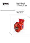
E62
The Best Electric Snowmobile Ever!!
Author, co-author (Do NOT enter this information. It will be pulled from participant tab
in MyTechZone)
Affiliation (Do NOT enter this information. It will be pulled from participant tab in MyTechZone)
Copyright © 2012 SAE International
ABSTRACT
The Clarkson University Electric Knights (CUEK) has
developed a lightweight snowmobile based on the Ski Doo
REV XP platform. The new snowmobile has a [50km (30 mi)]
range under optimal conditions; leading to an [18] mile
improvement. CUEK have been building electric snowmobiles
for participation in the SAE Zero Emissions Snowmobile
Competition since 2007. These six years of experience led to
better deign decisions and therefore, a better snowmobile.
The new snowmobile has greatly improved handling, range,
acceleration, aesthetics, and [electrical designs]. To do this,
the team utilized its knowledge to balance the weight
throughout the snowmobile, minimize weight while retaining
strength and structure in the motor mount design, optimizing
gear sizes, and [using a more efficient battery layout and
wiring].
The battery system consists of 900 LiFePo4 individual cells
that each provides 8.3 Wh of energy and up to 40 kW of
power. These batteries have superior thermal capabilities and
chemical stability. The use of MiniBMS by Clean Power Auto
as our Battery Management System (BMS) monitors the cells
and equalizes the batteries for safety and performance. The
use of an Azure Dynamics motor controller to manage a
highly efficient Azure Dynamics AC24 Motor that has a
continuous torque of 31 Nm at 4000 RPM helps to improve
our range.
chemicals in the atmosphere like a sponge. National Science
and Forestry’s Summit Station is performing research on such
chemicals that may be measured in only parts per billion.
Thus, a mode of transport that has zero emissions has been
sought after for many years. With the recent advancements in
battery and motor technology, it is now possible to fill this
need.
DESIGN STRATEGY
The 2011 snowmobile proved to be a great design. To build
upon the successes of the 2011 snowmobile design, Clarkson
Electric Knights decided to go with the REV XP snowmobile
chassis from a 2012 Ski Doo MX Z Sport 600 ACE. This
chassis is in the Ski Doo MX Z Sport with the Rotax 600 Carb
engine has a dry weight of 190.5 kg (420 lbs). A weight of
which is a 24.9 kg (55 lbs) drop in weight (previous sled’s dry
weight was 215.7 kg (475 lbs). The Rotax 600 Carb engine is
similar to the engine in the stock Polaris, so comparing the
weight of the two sleds this way better shows the difference is
the frame weights.
On the mechanical side of things, a two stage gear reduction
leads to an overall gear ratio of 3.2:1 with minimal lost in
efficiency through the use of custom tensioning, gears, and
two Gates Carbon Polychain Belts.
INTRODUCTION
National parks and other pristine areas that are
environmentally sensitive are in need of a mode of transport
that is quite, has zero impact on the environment, and can
travel long ranges on a single charge while also towing
equipment. The Greenland Ice Cap is such an area; absorbing
Page 1 of 12
Figure 1. Stock Ski-doo MXZ Sport 600 ACE.
In addition to a change in chassis, the 2013 Zero Emission
(ZE) snowmobile design strategy included dropping weight
where it was safe to do so. This is because a drop in weight
means the motor will not have to pull with as much torque in
order to accelerate the sled. Then the motor would require less
energy from the batteries, and thus the batteries will have a
longer life before they become to low to drive the sled.
Therefore, lighter weight directly leads to a greater range with
the same battery pack.
A greater range was another design goal. Concurrent with
dropping weight, the 2013 ZE Snowmobile has 84 more
individual LiFePo4 cells leading to a total count of 900
individual cells. To avoid complications with the electric
system, increase safety, prevent the need for repairs, and to
lower the 2013 ZE snowmobile’s MSRP, the use of more
simplified circuits and analog only BMS boards was
incorporated in the 2013 design. The basic design strategy
was to ‘keep everything simple” for safety and reliability.
Goals
The goal of the competition in Michigan is to determine
whether an electric snowmobile can be adequately used in
Greenland’s Summit Station by the NSF. Every event in the
completion is important, but from the experience of the CUEK
visiting Greenland, certain events stand out as more important.
These events are the range event, the draw bar bull,
acceleration plus load event, subjective handling, and cold
start events. By performing well at these events, it leads to a
snowmobile that can be very realistically used at Summit
Station in Greenland and effectively aid in the research being
performed there.
Table 1. The possible points that may be obtained for each
event. [7]
Zero Emissions
Class Events
Minimum points
for minimum
performance
Maximum
Additional
Points
Manufacturer’s
Suggested Retail
Price (MSRP)
2.5
50
Oral Presentation
5
100
Weight
0
100
Range
5
100
Draw Bar Pull
5
100
2.5
50
2.5
50
Acceleration +
Load Event
Objective
Handling and
Drivability
Page 2 of 12
Table 1. Continued. The possible points that may be obtained
for each event. [1]
Zero Emissions
Class Events
Minimum points
for minimum
performance
Maximum
Additional
Points
Subjective
Handling
2.5
50
Cold Start
2.5
50
Objective Noise
3.75
75
Subjective Noise
No-Maintenance
Bonus
Engineering
Design Paper
75
100
5
100
Static Display
0
50
Total
36.25
1050
When CUEK took the point weighting for the Clean
Snowmobile Challenge events into consideration, it was
decided that a focus of reliability, the range event and weight,
design of the snowmobile, and the draw bar pull event.
The draw bar pull event is the event where a snowmobile must
pull a progressive resistance in weight at four miles per hour
until it can no longer proceed due to a lack of traction and/or
power. During the event, the driver of the snowmobile is not
permitted to bounce the snowmobile so as to gain traction for
the sled. The maximum draw bar pull load is then measured
and recorded. Points are determined by awarding the winner
100 points and then using a linear scale to determine the
amount of points for each successive place.
For the range event, the judges set a speed limit of 20 mph that
the snowmobile must travel on a closed test course at until it
cannot move any farther. The team that travels the furthest
receives 100 points. Based on a linear scale, teams who
compete in the event will receive an appropriate score where
the team that achieves the least amount of miles in range will
be given a score of 5 points. 5 points will be given to team that
achieves the minimum requirement of 500 feet. As for the
weight event, each team’s snowmobile will be set on scales
during inspection to determine each sled’s weight. The team
with the lowest weight receives 100 points. Once again a
linear scale will be employed.
Reliability was most important to CUEK this year. This is not
only because reliability will aid in avoiding complications that
have arisen in past years and that have then impeded on past
performances. The other reason for reliability being a top goal
is because there is a one hundred (100) point no-maintenance
bonus. Any team that does not need to repair or service their
sled during the completion will receive 100 points. Reliability
in CUEK’s design goals is important in considering the use of
the Zero Emissions snowmobile. The snowmobile is meant to
be used by researchers in remote areas where maintenance and
repair will be scarce.
Good design is incredibly important in engineering. By
considering the life cycle of the snowmobile in one’s design,
one not only develops a better snowmobile, but reduces costs
in manufacturing. Thus, it leads to a lower MSRP. An
excellent design also leads to less need in maintenance over
the life of the produces and a greater level of reliability in the
product. Good design is rewarded in the SAE clean
snowmobile challenge in no only the events such as the range
event and the draw bar pull event, but in the Design Paper and
the Oral Presentation. In these events, a team can explain their
thought process behind their product. These two events total
200 points, which should encourage teams to put time and
effort in their design. CUEK noticed this and plan their work
so that CUEK develops good designs. [8]
INNOVATION AND PAST WORK
A key point in the design this year was incorporating new
ideas, change established norms, and introduce a new electric
snowmobile that is not only functional, but ascetically appears
close to stock. Everything was kept simple. The design of the
motor mount, the gearing, and the battery box can all be sold
as simple conversion kits that anyone could use to convert
their Ski doo REV XP to an electric snowmobile in a
weekend. In the drive to drop weight, a motor mount was
designed that does not even weigh in about 15 lbs. Where it
was safe and convenient, aluminum gears were utilized in
place of stock iron or steel. The only material added to the sled
was material deemed necessary for rigidity and safety under
the worst conditions.
Though the University of Alaska at Fairbanks has used the
Rev XP chassis before for conversion to a ZE Snowmobile,
The Clarkson ZE snowmobile has a more even weight
distribution and differs in almost every other aspect. The use
of two stage gear reduction that was optimized with
consideration of space restrictions greatly increases our
efficiency and is new to this chassis. Another goal with
gearing was to design the gears so that transmission of energy
through the drive train would be efficient and lead to a higher
acceleration. A larger torque at the gear connected to the track
is desired so that improved performance can be seen in the
draw bar pull. The 2013 snowmobile by CUEK is innovation
in its simplicity with reliability at the top.
Previous Work
Over the last six years, the Electric Knights have worked to
convert an internal combustion (IC) snowmobile to a fully
electric utility snowmobile. This past year, safer, more
Page 3 of 12
reliable batteries were chosen to power the snowmobile; an
improvement over the lithium polymer cells used in previous
versions of the snowmobile. These batteries needed to meet
specifications for output current, voltage, and operate in
conditions required by competition and the NSF. An energy
density that is as high as possible is desirable so that the cells
supply as much energy as possible at a lower cell weight. A
high power density or volume power density is also desirable.
This is because if each cell has a higher power density, less
space will be taken up by each cell, and thus when constrained
in a specific space, there will be more energy in the
constrained space. With a high energy density and high power
density, it is possible to get the power needed to complete the
events that require the snowmobile to run under a load. With
more power the events such as the Draw Bar Pull as well as
the Range event are accomplished more easily.
As the main power system involves a large quantity of cells, it
is essential to use a Battery Management System to normalize
the system. This BMS equalizes each individual pack as well
as preventing any pack from sinking below the minimum
operating voltage. By protecting the batteries from falling
lower than its minimum voltage, no one battery will cause the
entire battery system to perform inadequately or fail. Included
within the BMS is the capability to sense variables of each
battery pack to allow the user to monitor the system. A close
watch of the temperature, voltage and current output of the
batteries can be used to keep the snowmobile operating safely.
For example high temperatures, currents or drops in voltage
are all indications that the snowmobile needs to be serviced.
Balancing the speed and torque applied to the track is also
necessary to increase the snowmobile’s performance when
towing a load. The use of a more efficient motor controller
allows more power to pass from the main battery system to the
motor increasing both speed and torque and the range of the
snowmobile. Secondly, the gear ratio can be adjusted. Speed
and torque are inversely related with this adjustment; in other
words an increase in speed leads to a reduction in torque and
vice versa. With somewhat less emphasis on acceleration and
the event requiring the snowmobile to tow 500 pounds for 500
feet, more torque is needed. While taking into account that the
events are still time based, ratios for gears still need to be able
to provide the torque needed, at the same time moving at a
utilitarian speed.
Another improvement made to the conversion was the
elimination of the oil-filled chain drive system that is found
stock on the IC Snowmobile. Instead a belt driven drive
system was implemented. Use of a belt driven system, instead
of the chain drive makes the snowmobile substantially quieter.
Not only does switching to this system help with the noise
event, but in fact it played an important part in helping with
the handling of the snowmobile. In the process of switching to
a belt driven system, the placement of the motor was altered.
The motor was moved to a position lower than it was in
previous years allowing a more desirable center of gravity for
the snowmobile, improving handling. Through past years at
the Clean Snowmobile Challenge the weight of the
snowmobile has varied due to changes in the design. To help
improve performance, the team sought to reduce weight where
possible on new and existing components on the snowmobile.
With a lower weight, less energy will be needed in the
snowmobile, thus giving it a larger range.
Finally, a reasonable cost is preferable, and since cost is one of
the main goals, there was a very large portion of time spent
researching the least expensive parts that would not sacrifice
the safety or overall performance of the snowmobile.
Reliability is also very important to CUEK, so careful
planning and design when into BMS choices, battery cell
choices, and mechanical designs.
BATTERY MANAGEMENT SYSTEM
CUEK spent time looking at different BMS systems to
regulate the battery pack. In the past CUEK has had mixed
reactions with BMS systems. Some were custom built while
others were purchased systems. In 2013, CUEK chose the
miniBMS for simplicity reasons; it’s a hands off system as far
as user preferences and interface goes. You can view the
important information about your pack and not much more. In
the past experiences there have been issues with more
complicated and in depth systems which will give the user
more information on the pack. These systems frequently had
issues with reliability and seemed to ‘fault’ for no apparent
reason. The miniBMS is also more powerful than previous
systems. It can discharge 750mA [1] from each individual cell
versus a previous 250mA. This was an important factor to
consider when choosing a BMS since the balancing Lithium
cells is very important for pack health and safety and life.
Figure 3. Wiring Diagram for the MiniBMS [1]
MOTOR CONTROLLER
CUEK chose the Azure Dynamics DMOC445 motor
controller to regulate an AC24 motor. It is marketed as rugged
and waterproof. It has an inverter for controlling 3-phase AC
motors and generators. This motor controller was chosen
based upon its past successes in our previous work. It is very
configurable by the user to optimize individual settings and
requirements. This model also boasts gold Irradiated per MILC_5541-E-Class 1a as a component cover for corrosion
protection. The base of the heat sink is also comprised of this
material.
Figure 4: DMOC 445 Motor Controller
Figure 2: MiniBMS
The BMS boards should be installed with the ring terminal
attached to the negative side of the battery terminal. The red
lead wire will then be attached to the positive terminal of the
battery. In accordance with the user guidelines for this
particular BMS board we attached the BMS terminals on top
of copper links.
Page 4 of 12
The maximum and minimum cooling pressure for the motor
control on the inlet side is 12-10 psig, while the maximum and
minimum cooling temperature at the inlet is +55C and +40C.
The cooling flow rate is 7.5 to 10 LPM at 1.4 and 2.5 psi,
respectively. [3]
Table 2. Specifications on Motor Control [3]
BATTERIES OVERVIEW
For this build CUEK considered several battery options to
assemble the battery pack. One goal was for the batteries to
output more power while staying within the optimal voltage
for the motor controller. CUEK needed a battery that could
output a lot of power, be resilient to the effects of cold, have a
high energy density and most importantly, be safe.
Immediately, CUEK considered a few different lithium iron
phosphate cells (LiFePO4). This chemistry has worked
incredibly well for CUEK in the past and is much safer than a
lithium polymer cell.
In design you need to consider the entire life of the product. In
this case, one must consider how the batteries will be recycled
or reused at the end of the snowmobiles life. When compared
to other batteries, LiFePO4 have the best balance of safety,
cost, and end of life environmental impact.
FUSING
The importance of fusing a battery pack in an electric vehicle
is very important. In the event of failure fuses will protect the
pack from and the user from damage. Since our pack was built
from many smaller cells assembled in parallel and series we
needed to protect the parallel connections should a cell short
out or a short occur within the pack. To do this we used fuses
with axial terminals, we mounted these to tabs spot welded
onto the cells, and this prevented any damage to the cells from
soldering. Using direct mounted rated fuses we bypassed any
need for complex monitoring systems of the fuses. This
would’ve been very difficult since we have so many parallel
connections. Our pack is also fused by a full power rated fuse
as another method of protection.
In the past, CUEK has used K2 Energy 26650P cells, which
are a high output LiFePO4 cell in a small cylindrical case.
CUEK have been very happy with these cells in the past but
wanted to consider other types of cells. After much research
and then comparison of data sheets and discharge curves, the
same K2 cells were decided to be used once again. These
cells are arranged into fifty packs in series. Each pack is
comprised of eighteen cells in parallel.
Battery Container and Design
Fitting all 900 cells was going to be a challenge it works out to
be a big heavy pack no matter what. There is one large battery
box that contains the battery cells and the BMS boards. It is
placed under the driver. A large amount of design went into
the battery box. This location is the same location as the
original fuel tank. To contain all the batteries in one box helps
to simplify the design and makes maintenance easier.
Figure 5. 16 amp fuses with 250 volt rating. []
The fuses are rated for 16 amps and 250 volts. The fuses have
an interrupting rating of 500 A. Nominal cold resistance is
0.0031 ohms. The nominal melting is 1408.0 A2 sec. The
addition of these fuses between each battery cell greatly
increases the safety of our battery back since they work as a
first response. There are fuses in between each pack of cells.
Page 5 of 12
Figure 6. Mock-up of battery box in SolidWorks
Aesthetically, the sled does not look exactly like stock since
the battery box extends behind the seat. The battery box not
only protects the batteries from the snow and the environment
but it also protects the rider from the batteries in that rare case
of failure. The battery box is structurally sound and strong
through the use of an aluminum frame and polycarbonate
siding. The polycarbonate also works as an electrical insulator.
Aluminum of 1/16” thickness was used to fireproof the battery
box in compliance with the 2013 ZE Rules.
Comparing the discharge curves below the K2 energy cells
appear to output less power at the same current rating. Since
the K2 cells are only 2.6Ah, vs the 12Ah of the headway cells
looking at the 5amp load for the K2 cells gives a much better
picture of how the cells would perform if a ~12Ah pack made
from K2 cells would be tested.
Another reason for mounting the pack under the driver is to
give the sled a more centralized weight distribution. In the past
the sled has had a somewhat front heavy snowmobile. With
most of the weight on the front skis, turning the sled could
become difficult. This made it hard for some people to handle
the sled. The new sled does not have this issue and handling is
much improved. The battery box must contain 900 batteries
safely. These 900 batteries are 160.7 lbs (72.9 kg) alone. A
typical tank for an IC snowmobile holds around 42 lbs of
gasoline. The BMS boards and the aluminum frame also add
some further weight.
Another deciding factor for using the K2 cells was the size
factor, the smaller diameter cut down on the amount of lost
airspace between the cells. Also the larger size of the cell
restricted how the pack can be laid out. Considering the goal
of keeping the pack hidden and the seat at near to stock height,
the headway cells clearly had a disadvantage.
The construction of the pack is complicated due to the need
for strength and safety. CUEK chose to do a polycarbonate
box braced with angle aluminum for rigidity. To hold the pack
down and keep the lid on, CUEK designed ‘straps’ made out
of square aluminum tubing, these bolt to the chassis and form
a cage around the pack. This cage gives the sled a simple way
to hold the lid on, keep the pack firmly mounted in place and
creates a location for the seat to be mounted on.
Battery Selection
Figure 8. K2 Energy cells’ discharge rates for different
currents. [5]
After much research, comparison of data sheets and discharge
curves we settled on the same K2 cells, as tried and true
performers and 12Ah cells made by Headway Headquarters.
The advantage to the headway cells would’ve been a fewer
parallel connections between the cells only 4 versus 18. They
also featured bolted ends. We purchased several test cells and
discharged them several times under various loads to observe
temperature rise and voltage drop.
Despite the simplified electrical systems that the Headway
cells could provide, they had one more downfall that CUEK
didn’t initially expect. The bolted connections seemed better
on paper than in reality. While they were easy to put together
and take apart, they were somewhat limiting on pack
configuration since one would have to use a special tool to
access to the terminals and the extra space would be taken up
by the terminals and bolts.
Voltage under 32 Amp Load
4
3
Voltage
under 32
Amp Load
2
1
19
15
11
7
3
Time
0
Figure 7. Head way cells’ voltage discharged under 32 amps.
Page 6 of 12
DRIVE TRAIN
CUEK’s 2013 Snowmobile is zero emissions by its ability to
run on only LiFePO4 batteries. This makes the gasoline
engine superfluous and so it is removed. Removed along with
the engine are the continuously variable transmission (CVT),
fuel tank, muffler, and other associated parts. In place of these
parts, an Azure Dynamics AC24 Motor and DMOC445 Motor
controller were added. Though a CVT is very efficient by
automatically adjusting to the necessary gear ratio, the CVT
becomes unnecessary when using an electric motor. Gearing
however, is still an essential part of the design. This is because
the power from the motor can be transmitted efficiently and in
the desired manner. A light weight and efficient way of
transmitting power is through the use of a belt. Belts are
lightweight and usually have a high efficiency value. After
doing research on what is available, CUEK decided the best
choice for the drive train was to use a Gates Poly Chain GT
Carbon belt. In choosing what belt would be best for CUEK’s
snowmobile, consideration was made towards efficiency,
loudness of the belt while in use, cost, and ease of use.
Timing belts or synchronous belts are a positive transfer belt
that has teeth that fit into sprockets of matching tooth pitch.
They require little tensioning and typically replace chains in
designs. Timing belts also have no need for an oil bath unlike
chains.
Table 3. Comparison of Belt. [2]
Belt
Efficiency
[%]
Loudness
[dB]
Cost
Ease
of Use
V-belt
90-95
<60 dB
low
simple
Timing
98
73 dB
moderate
simple
Timing belts are also very efficient in transfer of motion as
they have no slippage when under correct tensioning.
Disadvantages in using a timing belt are inability to use a
clutch and cost. When using a timing belt, special sprockets
must be used and the belts themselves are usually more
expensive. In designing a zero emissions snowmobile, a clutch
is not needed as the motor controller can modify the RPM.
Vee belts (also known as V-belt) is the basic belt in power
transmission. They have little to no slippage or misalignment.
They typically have long life spans though they can lose up to
5% efficiency over a belts life [2]. V-Belts can withstand high
speeds and large loads. They typically require larger pulleys
since they have a large thickness. A wider width would not fit
in the area constraints of the Rev XP chassis, so a timing belt
would not work in this application. As can be seen in Table 2,
Timing belts have a greater efficiency.[2] For this reason and
for the other benefits of choosing timing belts, such as its long
life and reliability (no slippage even over time), a timing belt
was chosen over the V-Belt.
Gear choice is very important in designing the drive train.
Different gears can withstand different rotations per minute
(RPM), have different weights; have a direct effect on power
transfer and torque. Maximum speed and acceleration are
determined by the gearing. As for gears, CUEK chose to use
C3 Powersports 63-tooth sprocket gear in the bottom of the
chain case and their 30 tooth sprocket at the top of the chain
case. On the top of the motor side (on the jack shaft) is a 45
tooth gear from Gates. On the motor’s shaft of the same side is
a 30 tooth gear was custom made motion systems. All the
gears have a 8mm pitch. Both belts connecting the gears are
Gates Poly Chain GT Carbon synchronous belts in the two
stage gear reduction.
Page 7 of 12
The 2013 snowmobile has an overall gear ratio of 3.15:1. This
was found through the following equation:
In CUEK’s history, gear ratio has not been constant. In 2008 a
gear ratio of 5:1 where 80 Nm of torque at 4000 RPM was
outputted. During the draw bar pull, the sled lost traction due
to too much instant torque. In 2009, the gear ratio for the drive
train was 2.5:1. This led to a 5kg loss in weight and the ability
to perform well in the draw bar pull event. Greater torque was
desired in the 2010 build so the gear ratio was then increased
to 4:1 leading to a total torque of 360 Nm. The ratio of 4:1
permitted the snowmobile to pull 737lbs before losing
traction. The 2013 snowmobile now has a motor that can
output higher torques (peak torque of 75 Nm).
CUEK calculated through the gearing and was able to
determine the RPM of each gear and the tensioning pulley. At
peak torque running with an efficiency of 95%, the torque out
to the track is 224.7375 Nm. The power out with the same
efficiency is 28.353 Kw at peak torque. This means the force
out to spin the track is about 2244 N. Theoretically, when the
sled moves at 3.5 m/s2 with an extra load of 500 pounds, the
force needed to move the track is equal to 2067 N. The sled
will be able to overcome static friction and pull 500 pounds as
will be necessary in the acceleration plus load event and the
draw bar pull. If the sled is moving at 1 m/s, this means that in
5 seconds, the sled with reach 5 m/s and in 10 seconds, the
sled would reach 10 m/s. The speed of m/s is about 11.18 mph
and 10 m/s is about 22.36 mph. At this acceleration, the sled
can easily tow over our previous best of 737 lbs. The throttle
on the snowmobile is very sensitive so the torque is slowly
increased with the motor controller. This will improve the
subjective handling.
MOTOR
The motor in the 2013 snowmobile is an Azure Dynamics
AC24 induction motor. The motor has a high efficiency that
peaks at 89% when running at 156 VC and 91% at 336 VDC.
The motor weighs 38 Kg (83.8 lbs) and has
minimum/maximum operating temperatures of -40°C to 55°C.
[4] The ability of the motor to run at such low temperatures is
imperative of any motor used in such applications as at the
Summit Station in Greenland.
Figure 9. Picture of the Azure Dynamics AC24 Motor. [4]
The motor has two recommended optimal voltage it should
run at, 156 VDC and 336 VDC. CUEK planned in 2012 to use
this motor at 336VDC until the new rules for 2013 were
released. The new rules state we must not run above 300 V so
the lower optimal voltage had to be chosen. At 156 VDC, the
motor outputs 75 Nm at peak torque. The continuous torque at
this voltage is 31 Nm at 4000 RPM. 4000 RPM is also the
nominal speed. [4]
The efficiency of this new motor is consistently higher for all
torques. The efficiency versus torque for CUEK’s old
Solectria AC21 curve is not as flat as the presently used
AC24.
Figure 11. Efficiency versus torque for the AC24 motor at
336V. [3]
When comparing figure 4 and figure 5, the peak percent
efficiency is higher for the AC21. The AC24 motor however,
maintains efficiency between 75-85% for the entire range of
torques. As for the torque-speed envelop, the AC21 motor
curve can be seen in figure 9 and AC24 curves can be seen in
figures 10 and 11.
Figure 11. Efficiency versus torque at 156 V. [3]
When choosing a motor, it is very important to look at the
torque curve and consider how the motor will work with the
gearing in the vehicle. Below in figures 12-14, one can see
the torque versus speed curves for the old AC21 and current
AC24 motors. Speed is measure in RPM and torque is
measured in Nm. The two plots for the AC24 motor also show
the curve of peak output power versus speed. The units on
power are kW. You should note the speed at which there is
peak output power is the same speed at which there is peak
torque.
Figure 10. AC21 Motor Efficiency versus Torque curves.
Page 8 of 12
longer range of speeds. The peak power is about 10 kW
greater when running 336 V.
Motor Mount
The motor mount design is based closely on the 2011
snowmobile motor mount. The area in which the mount is
placed is smaller with ununiformed angles, making the design
of the motor mount more challenging. The most obvious place
to put the motor is in the area that the IC motor was. In this
position, the weight of the motor is very low. With it in this
position, the handling will be improved from previous years.
Figure 12. Torque-Speed envelop for the old AC21 Motor
Figure 13. Torque-Speed envelop for theAC24 running at
156 VDC with a peak power curve versus speed in RPM. [3]
The Torque-speed envelope
Figure 14. Torque-Speed envelop for theAC24 running at
336 VDC with a peak power curve versus speed in RPM. [3]
The original strategy of CUEK was to run the motor at 336 V.
If the sled is run at this voltage, the peak torque is higher for a
Page 9 of 12
Because of the confined space, the motor mount had to be
carefully designed. To increase the structure of the lower
motor mounting arms, the lower mount arms were designed to
fit the pan perfectly.
Figure 15. Stress on face plate connected to the motor.
A finite element analysis on the entire mount was done along
with a simple static and strength of materials analysis to check
the safety of the design. The main face plate that bolts onto
existing mounting holes of the AC24 motor was machined
pout of 6061-T6 Aluminum. The maximum stress at the
maximum torque the motor can produce is 1000 psi. In figure
15, one can see the stress study performed on the face plate.
Figure 18.The stresses on one of the lower mount arms.
Figure 16. Assembly of the motor mount with the motor in
Solid Works
The motor mount consists of two of these lower mount arms
which follow the profile of the pan perfectly. The tight fit aids
in the structure of the mounting.
The blue color represents 2.6 psi, the green represents 507 psi,
the orange is 843.4 psi, and the red represents 1000 psi.
Below, in figure 17, one can see the displacements of points of
the face plate due to maximum torque.
Figure 19. Displacements on the lower mounting arm.
The red color in figure 19 shows the greatest displacement the
lower mounting arm might experience. This displacement is
3.3x10⁻⁵ inches. There is very little possible displacement and
stress in the motor mount parts. These tiny displacements
mean the motor mount will not vibrate much and therefore,
will be very quiet.
Figure 17. Displacements on face plate that attaches to the
motor. Units are between 10-8 and 10-4inches.
The red represents 1.6x10⁻⁴ in, orange is 1.34x10⁻⁴ in, the
yellow is 1.2x10⁻⁴ in, the green is 8.0x10⁻⁵ in, and the blue
represents 2.55x10⁻⁸ in.
One of the unique things about this motor mount is it is very
easy to install, light weight, and can be adjusted for a large
range of belt sizes. Everything is still kept simple and easy to
machine. The only parts of the motor mount that are harder to
machine would be the lower mounting arms which had been
machined through the use of a computer numeric control
(CNC) in house. Below in figure 18 are the stresses on the
lower mounting arms.
Page 10 of 12
HANDLING
One of the events at the Clean Snowmobile challenge is the
subjective and objective handling event. Handling is clearly
important since no matter how fast or efficient one’s sled
might be, if it has bad handling, no one would purchase or use
it. So good handing was one CUEK’s design goals. As
discussed earlier, handing has never been the best on CUEK’s
snowmobiles. This new build however, has taken a large
majority of the weight that use to be in the front and
distributed it under the seat. The weight was designed as low
to the ground as possible to have a low center of gravity. A
lower center of gravity greatly improves handling around
turns. Because the batteries add significant weight, two new
rear torsion springs two grades above stock were used in the
rear suspension. This will allow riding of the snowmobile over
large bumps like one would with the stock snowmobile.
9. Littlefuse. 215 series, 5 x 20 mm, Time-Lag Fuse.
Littlefuse, 2012.
Braking
The breaks in the snowmobile were all kept stock. No
modifications to the break were made. Plans have been made
to incorporate regenerative breaking into the electric
snowmobile. Unfortunately, this could not be utilized on the
snowmobile this year.
CONTACT INFORMATION
SUMMARY/CONCLUSIONS
The Clarkson University Electric Knights would like to
gratefully acknowledge the support of Clarkson University
SPEED Program, ECE and ME Department of Clarkson
University and Clarkson University. The team would also like
to thank its sponsors, C3 Performance, Gates Corporation, K2
Energy, and Ingles Performance. Without their support, this
electric snowmobile would not have been possible. We would
also like to thank Professor Morrison, Jonathon Young and the
other employees in the CU Machine Shop.
Based on the Ski doo REV XP platform, a zero emissions
snowmobile was designed and built by Clarkson University
Electric Knights. The new 2013 ZE snowmobile is
theoretically capable of reaching speeds around 60 mph (96.5
kmh) in optimal conditions. The motor mount, the battery box,
and the gearing can all be sold as conversion kits. The key
word for the design this year was reliability. All analog BMS
boards were used, and the circuitry was simplified.
REFERENCES
1. Auto, Clean Power. MiniBMS User Manual. User Manual,
Clean Power Suto, 2012.
2. "Belt (mechanical)." Wikipedia. n.d.
http://en.wikipedia.org/wiki/Belt_%28mechanical%2
9 (accessed February 2, 2013).
3. Dynamics, Azure. DMOC445 and DMOC645 User Manual
For Azure Dynamics DMOC Motor Controller.
Azure Dynamics, 2010.
4. Dynamics, Azure. Force Drive Electric Drive Solutions.
Azure Dynamics, 2010.
5. Energy, K2. "High Capacity LFP26650P Power Cell Data."
2010.
6. Energy, U.S. Department of Energy: Energy Eddicency and
Renewable. energy.gov. n.d.
http://www1.eere.energy.gov/manufacturing/tech_de
ployment/pdfs/replace_vbelts_motor_systemts5.pdf.
Feb. 2013
7. International, SAE. "2013 SAE Clean Snowmobile." 2013.
8. Keith Nisbett, Richard Budynas. Shigley's Mechanical
Engineering Design. New York, NY: McGraw-Hill
Companies, 2010.
Page 11 of 12
Lindsay Borakove: [email protected]
ACKNOWLEDGMENTS
DEFINITIONS/ABBREVIATIONS
BMS – Battery Management System
IC – Internal combustion
CUEK – Clarkson University Electric Knights
RPM – Rotations per minute
CNC – Computer Numeric Control
CVT – Continuous Variable Transmission
Page 12 of 12