1
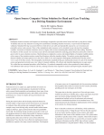
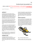
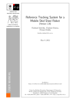
2015-01-XXXX
Open Source Computer Vision Solution for Head and Gaze Tracking in a Driving
Simulator Environment
Author, co-author (Do NOT enter this information. It will be pulled from participant tab in
MyTechZone)
Affiliation (Do NOT enter this information. It will be pulled from participant tab in MyTechZone)
Copyright © 2015 SAE International
Abstract
Inadequate situation awareness and response are increasingly
recognized as prevalent critical errors that lead to young driver
crashes. To identify and assess key indicators of young driver
performance (including situation awareness), we previously
developed and validated a Simulated Driving Assessment (SDA) in
which drivers are safely and reproducibly exposed to a set of
common and potentially serious crash scenarios. Many of the
standardized safety measures can be calculated in near real-time from
simulator variables. Assessment of situation awareness, however,
largely relies on time-consuming data reduction and video coding.
Therefore, the objective of this research was to develop a near realtime automated method for analyzing general direction and location
of driver’s gaze in order to assess situation awareness. Head tracking
was employed as a proxy and standard display of computer readable
patterns at the corners of the simulator monitors created fixed
locations within the simulator display. The analysis system
algorithmically detected whether each unique pattern was in the
driver’s field of view and computed a homography transformation
from the camera view to each of the three screens. The homography
transformation standardized the gaze tracking data streams for each
of the simulator screens and generated corrected scene-view videos
for manual validation. All software and immediate dependencies are
open source. We verified that our automated procedure, called
SimGaze: (1) produced comparable results to those produced by hand
coding of well-calibrated videos and (2) worked in real time,
reducing researcher time required for analysis and improving the
simulator report.
example, many recent driving safety research studies utilize human
coding to distill eye, pupil, and head motion data into quantifiable
metrics [8]. The challenge facing simulation researchers is that such
rich graphical datasets are tedious but possible for humans to analyze
but difficult to translate into calculation. Many solutions for
analyzing dense data such as this have not yet been effectively
implemented. Those that have been effectively implemented remain
prohibitively expensive for many research institutions. Development
of an open source set of computational tools for processing simulatorbased graphical data could save human time for research, potentially
speeding up the rate of progress in the field.
This paper aims to develop a general set of free and open source
methods and software to reliably detect, capture and analyze head
and gaze movements during simulated driving. The specific
computational method involves the placement and automated
detection in standardized positions in the simulated scene. This
manuscript presents the methods for implementation of this technique
in the context of a driving simulator.
Methods
Introduction
Numerous devices to capture eye, pupil and head movements are
readily available for research purposes. In particular for driving
safety research (both naturalistic and simulation), these types of data
are used to develop standardized metrics and reliably assess driving
performance in a variety of complex driving environments and
scenarios [8].
During the analysis phase and developing analytical datasets for
research studies, a large amount of time and resources are exhausted
to synthesize these data and provide meaningful insights. For
Page 1 of 12
Figure A: Representation of Overall Method
Here we describe a solution we call SimGaze, which synthesizes
several existing tools to “bridge the gap” between the data acquired
by an eye tracker and the simulator screen context, and acquire
information in the context of the simulator screen. The system makes
it possible to quickly analyze with a computer, where before it had to
be manually reviewed. In brief, we use the ASL eye tracker to gather
initial gaze information and the APRIL Tags software to gather
spatial information. Using the OpenCV library, we then compute a
homography transform that maps the video and gaze information to a
common screen-relative coordinate system. From this point the data
can be analyzed using simple methods in MATLAB.
with a 60-Hz frame rate. SimObserver, a video capturing system,
allowed for analysis of digital video recordings along with recorded
simulator data. Videos of the driving scene, of the participant’s hands
on the wheel, and of the participant’s foot were recorded.
Figure 1: Driving simulator at the Center for Injury
Research and Prevention at the Children Hospital of
Philadelphia
Some productive tests of driver safety rely on knowing where the
driver is looking at specific times. For instance, when the driver is
turning left, a key indicator of safety is whether or not they look left
in order to check for oncoming traffic. Another indicator of safety is
whether drivers pay attention to the cars they are following, and
whether they check hazardous areas such as perpendicular driveways
before driving past them.
Figure B: Representation of SimGaze Computation
Driving Simulator Environment
The purpose of this section is to introduce the Driving Simulator that
was has been as a platform for the SimGaze and SDA projects.
The Simulated Driving Assessment developed at the Center for
Injury Research and Prevention (CIRP) at the Children Hospital of
Philadelphia (CHOP) has been hosted on a fixed-based high fidelity
Realtime Technologies, Inc. (RTI) ® driving simulator. Data was
collected at 60 Hz with a fixed-base high fidelity Realtime
Technologies, Inc. (RTI)® driving simulator. The driving simulator
consists of a driver seat, three-channel 46” LCD panels (160° field of
view), rearview mirror images inlayed on the panels, active pedals
and steering system, and a rich audio environment. The graphics were
generated by a tile-based scenario authoring software, and real-time
simulation and modeling are controlled by SimCreator, (RTI®).
Visual rendering and graphics are delivered at 1280 x 1024 resolution
Page 2 of 12
In previous efforts, these tests have been performed using an eye
tracking headset called the ASL eye tracker, which records and
indicates where the participant is looking on the screen in real time
by superimposing an indicator dot on the video feed from the
headset’s front-facing camera. This method makes it simple for a
human to look at the video output from the tracker and to evaluate
whether the participants were looking at correct areas of the screen at
the correct time. However this mode of analysis, known as video
encoding, is quite slow. Thus a computer assisted approach would be
highly desirable. However, the data poses a significant challenge to
computer-automated data analysis, because as the participant rotates
or translates their head, the front-facing camera angle changes,
meaning that the coordinate system in which the participant’s gaze is
recorded is not locked rigidly to the simulator screens. This means
that the gaze point information must be transformed into a screenrelative coordinate system before it can be used for automated video
encoding.
The ASL Tracker
The purpose of this section is to introduce the eye tracking equipment
used to collect data during driving in the simulator. We discus two
trackers, their comparative merit, and how the collected data was
parsed by the system.
The section implies that the ASL was ultimately chosen over the Pupil
because it tracked a user’s gaze more reliably than the Pupil.
The ASL tracker is a head mounted eye tracking system that works in
real time. The ASL consists of a pair of modified glasses with an
inward facing infrared camera and an outward facing camera, similar
to the Pupil tracker. (See Figure 3) The inward facing camera tracks
the movement of the participant’s left pupil and uses the information
to make a guess about where the participant is looking on the video
from the outward facing camera. (See Figure 2) The system can be
calibrated for individual users using a piece of desktop software that
connects to the tracker via wi-fi. The system outputs a CSV file
containing gaze locations (frame normalized, from top left) and
timestamps (in seconds, from video start), and an AVI file from the
front facing camera with a visual indication of the user’s gaze
superimposed. (640x480 @ 30-Hz) The inward and outward facing
camera design is common to many eye tracker headsets on the
market, making it an ideal development platform for this tool. In
theory, using an eye tracker from any of ASL’s competitors should be
just as easy as using ASL.
The Pupil Tracker
For development and testing, we also used a less costly but higher
resolution open source eye tracker from Pupil Laboratories, called the
Pupil Eye Tracker. The Pupil Tracker functions very similarly to the
ASL Tracker, but uses different hardware and software. The pupil is
built from two webcams (front-facing: 1280x720 @ 30fps, rearfacing: 640x360 @ 30fps) and a 3d-printed frame.
Integrating ASL Video
The SimGaze system uses the ASL video in its tag detector (Pupil
video was used in an identical process before ASL support was
added). Given the path of the video, the system opens one frame of
the video at a time and performs specified analysis before closing the
frame and opening the next in the sequence. The analysis performed
depends on the options with which the program is run. (See
Appendix: “List of Program Flags”) This is the main loop for the
program. The ASL video is never overwritten.
Figure 3: The Pupil Eye Tracker (from www.pupillabs.com)
Figure 2: ASL Front-Facing Camera View with Gaze Point
Integrating ASL Data
If necessary for a particular analysis, the system also reads one line of
data from a given ASL CSV file per frame analyzed. This
corresponds to one frame of output form the ASL system, so the two
data streams stay in sync by being read at a one-to-one ratio. The
ASL data is never overwritten.
We developed the software using the Pupil because it was open
source, which allowed us to edit its source code in order to make its
output easier to parse for the SimGaze system. In development, we
found that the Pupil camera videos produced tag tracking results that
were more reliable than those from the ASL. This may be due to its
higher resolution front-facing camera. However, the eye tracking
performed much more poorly than the ASL. Particularly, we found
that the Pupil gaze tracking calibration procedure was very
inconsistent between people, and did not work at all for many of the
researchers who tested it.
After developing the system, we added support for the ASL tracker,
which is now the standard tracker of use, however, we have full
support for the Pupil in the final product. Other labs could potentially
implement a set of fully open source head and eye tracking tools with
the Pupil for under $300 (if the Pupil tracker is constructed by the
lab). Also, since SimGaze is open source, the code can be easily
edited to add support for other trackers if need be.
The APRIL Tag Detector
The purpose of this section is to explain what the APRIL Tag
Detector is and discuss some of its features.
Page 3 of 12
The section implies that some specific settings are more optimal (than
default) for fast and accurate tag detection.
The APRIL Tags software is a tool that generates and detects
computer vision tags. (See fig 2) each tag is a square pattern of
smaller black or white squares that represents an integer. A tag can
contain different numbers of squares depending on the resolution of
the tag. Tags of higher resolutions can store larger integers, but they
tend to be harder for the APRIL Tag detector to detect accurately. We
used Tag36h11 type tags, which are a six by six grid of squares.
There are 587 unique tags of this resolution, numbered 0 through 587
[12]. The APRIL Tag detector is implemented in several languages;
we used the C /C++ implementation with OpenCV to maximize
speed and compatibility with its other components. The APRIL tags
software is open source, and has been shown to be faster and more
accurate than other tools of its kind, especially in varied lighting
conditions or resolutions. The APRIL Tag detector has several
parameters that can be changed and which affect the speed and
accuracy of detection in different conditions. It also outputs several
pieces of information for each tag detection relating to the accuracy
of the detection and the system’s confidence in the detection. Our
system can adjust the “decimate” and “sigma” values.
A lower decimate value provides more accurate tag detections at the
cost of speed. It is recommended to use a value from 1 to 2. This
setting defaults to 2.
A positive nonzero value of sigma will apply a Gaussian Blur to the
image, improving detection with images that are very noisy at the
cost of processing speed. If the video was noisy we found it was
effective to use a value of 0.8. If video was not noisy, setting a
nonzero value of Sigma decreased performance and negatively
impacted tag detection on good data. This setting defaults to 0.
by tag number should theoretically catch approximately 97.96% of
false detections. Additionally, this form of filtering is favorable
because it can never exclude a correct detection (such a detection
would have one of the specified allowable tag numbers).
The system can also filter the tags by goodness (unit-less double,
higher is better, outputted by the APRIL Tag Detector), and hamming
distance (integer, the number of black or white squares that needed to
be changed in the detector’s guess for it to match the number given).
Both of these filters can be adjusted by the user, but default to preset
values (30.0, and 2, respectively). In preliminary testing, we have
found that it is often better to leave these additional filters completely
open, in order to avoid excluding correct detections.
The SimGaze System
This section explains the actual system used to transform tag data
from the non-normalized coordinate system of the tracker to the
normalized coordinate system of the simulator.
The section implies that the system is functional and usable in its
current state, but does not discuss performance metrics. The system is
to be evaluated fully in future literature. In particular, the system is
scheduled to be used in a 60 person study at CIRP in March of 2015.
The SimGaze system is run as a command-line executable on a Linux
machine. A user gives the program instructions by adding flags after
the command. (e.g. “./sda --transform --visual -t "79 80 81 82 83 84
85 86 87 88 89 90" [input file].avi [output file].txt”) Flags do many
things, from controlling the APRIL Tag detector parameters, to
specifying desired tags or tag locations, or to turning on or off visual
output.
Commands always begin with “./sda” and end with the input file path
followed by the output file path. The flags go in between. Flag order
doesn’t matter. For a full list of program flags, see “List of Program
Flags” in the Appendix.
Figure 4: Selected April tags
The SimGaze Tag Detector
The SimGaze system uses the APRIL Tag detector to detect all
possible tags in each frame of video that is read from the ASL AVI
file.
We filter these detections in a number of ways. The system excludes
any tag detected that does not match any of the tag numbers given by
the user. (If the user fails to specify any tags, then all are included.)
The tags are surely false detections, because if the user has specified
all the tags that are actually in the simulator, then there is no real
world tag of any of those numbers for the system to detect. We are
using a relatively small number of the available tags at our resolution,
(12/587) and a false detection could be any one of them, so filtering
Page 4 of 12
Figure 5: Code Flow
The Tag Transform method (main method)
The Tag Transform method is specified by adding the flag “—
transform” to the execution command.
The SimGaze system used the Tag Transform method to transform
the data from the CSV file generated by the ASL into coordinates
systems defined by the three simulator monitors. (Thus the outputted
data is effectively in context with the simulator environment, rather
than the person.) In order to accomplish this, the system creates a
homography matrix using the OpenCV C library. The program stores
an expected tag layout as tuples contained in a CvMat. The tuples
relate to the locations of each corner of each tag on the simulator
screens. The tags are each defined in a coordinate system relative to
the screen they occupy, making three total coordinate systems. Each
system coordinate system is defined from the top left (x,y) in pixels.
Each screen has four tags in identical locations, so there actually only
need-be one set of four tags defined, which will describe all of the
twelve tags across three screens.
The system is also able to produce a video for each screen that is
stretched and translated to fit the perspective transformation for each
screen. It will also display a visual representation of the tags in their
pre-transform and post-transform position. This video is useful in
troubleshooting the system setup, because if the transformation is
wrong, the video will be visibly wrong. Often the video makes it easy
to identify common problems such as a tag that was entered in the
wrong order, or a missing tag resulting from the wrong number being
entered.
Figure 7: Original ASL Scene View
Figure 6: Tag Locations
For each screen, the system performs a separate homography
transformation. This is done because the points defined for a
homography transformation have to be planar. The monitors are not
all parallel, so the twelve tags are only planar with other tags on the
same screen. The user defines which tag numbers are on each screen
and which corner they are in. For each screen, the system compiles a
matrix of points containing the locations of the corners of all the tags
detected for this time-step that match with user specified tag numbers
for one of the corners of the current screen. (The system can compute
a homography matrix even if up three out four tags are undetected, so
any user defined tag that isn’t detected is replaced by (0,0), which
doesn’t affect the homography calculation.) The detected tag matrix
is formatted identically to the simulator-relative tag matrix.
Figure 8: Transformed Scene View
This matrix of simulator-relative tag locations, along with the
detected tag matrix for each screen is passed to the OpenCV function
“cvFindHomography().” The function produces a homography matrix
for each screen which relates the orientation of the front facing
camera to the orientation of that screen.
Each homography matrix is used to transform the gaze point from the
ASL csv file for that video frame from ASL coordinates into the
coordinate system for the screen associated with that matrix. This
action is performed using the “cvPerspectiveTransform()” function in
OpenCV. Transformed gaze information is printed in the output CSV
along with other relevant information. For a full list of CSV output
form the SimGaze system, see “List of SimGaze CSV Output” in the
Appendix.
Page 5 of 12
The Tag Detection Method
Although researchers initially used the method of video encoding
with the ASL to tell where the participant was actually looking in the
simulator to perform Left Look checks among the other tests, it may
be possible to perform this test without involving gaze information at
all using the SimGaze system.
The SimGaze system can track the locations and appearance of
individual tags on the screen and Tags can be placed in such a
location that they will only be visible to the outward-facing camera if
the participant is looking left. In setup with a tag placed as described,
researchers can use MATLAB to parse the SimGaze output file and
extract tag detections. Comparing the times of tag detections to the
times of relevant events in the SDA, the researcher can simply and
quickly determine if users made a left check or not.
Evaluating Transformed Data in MATLAB
Researchers at CIRP use a program called LiveMetrics in MATLAB
to analyze drive data and produce a score report for the participant
about fifteen minutes after they take the simulated driving test. Until
SimGaze was developed, gaze information was not able to be
included in the LiveMetrics score report, because video encoding
took too much time. Now that SimGaze can put gaze information into
a format that can be used in MATLAB, LiveMetrics can be updated
to use gaze information and SimGaze.
Researchers at CIRP hope to use LiveMetrics to evaluate drivers for
checking left when they turn left, making Hazard anticipation
Glances (HAG) [8], and not taking their eyes off the road for
extended periods of time. All of these checks are possible to automate
using the SimGaze output data. The LiveMetrics program can check
that a user is looking left by simply validating that the transformed
gaze point is past a cutoff in the X direction. Similarly, the system
can check if a participant is making a Hazard Anticipation Glance by
comparing the distance of the gaze point from the location of the
hazard on screen to a distance cutoff, and the system can check of a
participant is looking at the road by defining the area if the screen
that is acceptable as looking at the road, and checking if the gaze
point is within this area.
Discussion
Discussion of Open Source
Open source software is extremely valuable, because it allows people
all over the world to implement a solution once it is developed by one
person. Open source software is free to use, which reduces the barrier
of entry and level of commitment needed to engage in a project that
uses a given open source tool. However, perhaps, the most important
thing to notice about open source projects is that they are easy to
extend. For instance, in the development of the SimGaze system, the
APRIL Tags library and the Pupil Eye tracker library were both
modified from their original form.
The SimGaze system is also easily extensible. In our own research,
we were able to quickly add secondary support for the ASL eye
tracker. We are confident that support for similar eye trackers could
be easily added in the future, either by ourselves or by other users.
The SimGaze system is 100% open source. By date of publication,
the source code will be available on www.github.com for free
download or modification (forking). Additionally, all of SimGaze’s
dependencies are also open source, making SimGaze completely free
to install.
Discussion of Extensibility
It is important that the SimGaze system be usable for a wide range of
eye-trackers. To this end, it has been written in such a way that it can
easily be made compatible with new eye trackers, provided they
Page 6 of 12
output location data as a csv (comma separated values) file. Data is
read in and normalized from the csv file before being analyzed by the
SimGaze system, so to integrate a new eye tracker, a person simply
implements a separate method that parses the data in a way
appropriate to their tracker, and adds an option to use it instead of the
default. Once the system was developed, one researcher at CIRP was
able to implement a solution to integrate a second eye tracker (ASL
Eye Tracker) in under a day.
Tracker Evaluation
The SimGaze system is free and open source, so there are no costs
associated with it, but it requires the necessary hardware to acquire
gaze information. Eye trackers can be extremely expensive. The
system was tested with the ASL Eye Tracker, and the Pupil Eye
Tracker. The ASL is significantly more expensive than the Pupil.
(~$30,000 and $485 respectively.)
The ASL Tracker was used in the Center for Injury Research and
Prevention for this project because the center already owned one, and
researchers had been trained to operate it. However, the Pupil headset
actually performed better than the ASL in some ways, despite its
much lower price. (1) The Pupil had a higher resolution camera than
the ASL, which greatly improved tag recognition, and allowed for
smaller tags to be placed. (2) The Pupil was more comfortable to
users, and provided better peripheral vision than the ASL.
The ASL did outperform the Pupil in actual eye tracking.
Particularly, the ASL worked with most people, while the Pupil
exhibited very inconsistent performance between people. Thus, the
correct tracker to use with SimGaze depends on the application. For
development and testing, the Pupil is a better option, but for any
application that relies on multiple participants, the ASL or another
eye tracker not discussed will be better.
Conclusions
Testing the finished SimGaze System indicated that it was a viable
solution for automating data analysis in the Center for Injury
Research and prevention. The saves researcher time by eliminating
the need for video encoding, and it is also accurate enough to be used
for more specific future metrics.
Aside from saving time, the system improves on previous
methodology by allowing tracking to be done in near real time. In
other words, it can be run as soon as the data is collected from the
simulator and it takes a small enough amount of time (5-10 mins) that
a participant in the study could feasibly wait while it was done and
receive the results. As discussed above, CIRP uses a system called
LiveMetrics to perform a large set of different data analyses that
evaluate a participant’s driving while they wait. The fact that
SimGaze is near real time allows it to be integrated into the
LiveMetrics process at CIRP, marking the first time that eye tracking
has been included in the LiveMetrics score report. This is very
important, because previous work done with SDA has shown that
driver focus (gaze location) is an extremely important factor in driver
safety, but until the process could be automated, it was impossible to
include in the report.
LiveMetrics is also part of a larger effort to make the SDA platform
more accessible, so that it could one day be used outside of the lab as
a real means of driver safety testing in a DMV. LiveMetrics scoring,
including SimGaze analysis, helps make the SDA more accessible by
removing the need for a qualified evaluator.
The consistency of video encoding was insured using redundant
evaluations (which had to agree or else be re-evaluated by a third
party) and strict standards and training. This would be an unfeasible
process to replicate outside of the lab. However, automating the gaze
information analysis eliminates the need for these precautions
because anyone trained in the use of the system can analyze the data
and their results will be repeatable with the same data.
References
1.
2.
3.
4.
5.
6.
Matlab User’s Guide, The Mathworks Inc. 2013.
SimCreator User’s Manual, Realtime Technologies 2008
SimVista User’s Manual, Realtime Technologies 2012
SimObserver Users’s Manual , Realtime Technologies 2004
Data Distillery User’s Manual, Realtime Technologies 2009
Eye Tracker Systems Manual MobileEye XG, Applied Science
Laboratories, 2012
7.
McDonald, Catherine C., Thomas S. Seacrist, Yi-Ching
Lee, Helen Loeb, Venk Kandadai, and Flaura K. Winston.
"Headway Time and Crashes Among Novice Teens and
Experienced Adult Drivers in a Simulated Lead Truck
Braking Scenario." In 7th International Driving
Symposium on Human Factors in Driver Assessment,
Training, and Vehicle Design, no. 67. 2013..
McDonald, Catherine C., Jason B. Tanenbaum, Yi-Ching
Lee, Donald L. Fisher, Daniel R. Mayhew, and Flaura K.
Winston. "Using crash data to develop simulator
scenarios for assessing young novice driver performance."
8.
Page 7 of 12
InTransportation Research Board 91st Annual Meeting,
no. 12-1636. 2012.
9. Rozeboom, Richard, Bachelor Opleiding Kunstmatige
Intelligentie, and A. Visser. "April robotics laboratory
modules for usarsim." Project Report, Universiteit van
Amsterdam (2012).
10. Olson, Edwin, et al. "Exploration and mapping with
autonomous robot teams."Communications of the
ACM 56.3 (2013): 62-70.
11. Loeb, Helen S., et al. Simulated Driving Assessment: Case
Study for the Development of Drivelab, Extendable Matlab™
Toolbox for Data Reduction of Clinical Driving Simulator 9
Data. No. 2014-01-0452. SAE Technical Paper, 2014.
12. Olson, Edwin. "AprilTag: A robust and flexible visual fiducial
system." InRobotics and Automation (ICRA), 2011 IEEE
International Conference on, pp. 3400-3407. IEEE, 2011.
13. Kassner, Moritz Philipp, and William Rhoades Patera. "PUPIL:
constructing the space of visual attention." PhD diss.,
Massachusetts Institute of Technology, 2012.
Contact Information
For information contact author Devin Caplow-Munro
([email protected], [email protected])
Acknowledgments
We thank Catherine McDonald, Yi-Ching Lee, Dana Bonfiglio, Tom
Seacrist, Alain Hernandez, Andrew Winston, and Guyrandy JeanGilles for their efforts and the Center for Injury Research and
Prevention for their support
Definitions/Abbreviations
Pupil
The Pupil eye tracker from
Pupil Laboratories.
HAG
Hazard Anticipation Glance
CIRP
Center for Injury Research
and Prevention
CHOP
Children’s Hospital of
Philadelphia
ASL
Refers to the ASL Eye
Tracker from Applied
Science Laboratories
Page 8 of 12
Appendix
List of Program Flags
Flag
Usage
Notes
-h
Help: Displays a list of available
commands
Help is currently under construction. For
now, use the included reference.
-v
Enables verbose mode. Prints extra
information to the output console for
debugging.
Useful for debugging.
-d [VALUE]
Sets decimate value of the tag detector.
Takes Real value from 1 to infinity.
DEFAULT: 2.0
A lower decimate value provides more
accurate tag detections at the cost of
speed. It is recommended to use a value
from 1 to 2.
-s [VALUE]
Sets sigma value of the tag detector.
Takes Real values from 0 to infinity.
DEFAULT: 0.0
A positive nonzero value of sigma will
apply a Gaussian Blur to the image,
improving detection with images that are
very noisy. If the video is noisy it is
recommended to use a value of 0.8.
Otherwise, setting a nonzero value of
Sigma will decrease performance and can
negatively impact tag detection on good
data.
-gt [VALUE]
Sets the minimum goodness threshold of
Goodness is an internal measure of how
the tag detector. Takes Real values from 0 likely the tag is a true positive detection.
to infinity. DEFAULT: 30.0
A low value indicates that it is likely that
the detected tag is a false positive. This
flag is disregarded in favor of the -t flag.
We found that an appropriate threshold
changes from case to case, so filtering tags
with this method is unreliable.
-ht [VALUE]
Sets the maximum hamming threshold of
the tag detector. Takes Integer values
from 0 to infinity. DEFAULT: 2.0
-t "TAG1 TAG2 … TAGn"
Specify which tags to filter for. Will
This flag is useful when the user wants to
disregard all other tags not provided when filter out tags based on their id. We found
generating output files. Example: -t “01
it was preferable over using gt and ht, and
Page 9 of 12
Hamming distance is defined as the
number of error bits corrected in order to
make the tag detected. A low value means
that little to no correction was needed to
be, therefore this quality of detection was
good and the tag is likely a true positive.
As stated in goodness threshold, this flag
is usually disregarded in favor for the -t
flag.
--visual
79 85” will disregard all other tags
EXCEPT for tag id 01, 79, and 85. Tags
must be separated by spaces.
that tags with the specified ids can, in
most cases, be trusted as a true positive.
NOTE: The usage for this flag in the tag
perspective transformation code varies and
will be covered later. Users should be
warned that the program can not handle
more than 50 specified tags. This is an
extraordinary use case. If more tags need
to be specified change the variable int
max_tags in the main function to the
desired maximum value.
Enables visual mode. Displays the current
post-processed frame once it is done.
Useful for debugging.
Press any key to pause and restart the
video in this mode.
-vo [PATH TO OUTPUT]
Enables writing processed frame to an
.avi file with a path and name specified
by the user. Uses the same codec, frame
rate, and frame size as the input video
file.
--quiet
Enables quiet mode. The script will not
write an output text file.
Useful for debugging visual output.
-st
Enable small-tag detection
Good for low resolution detections, but
increases false positives, and is extremely
slow.
Although more tags are detected,
detections can vary widely in quality. Not
recommended for homography
calculations.
--pupil [PATH TO PUPIL
CSV]
Enable pupil gaze tracking support.
Loads a csv file for pupil tracking.
The “-npy” modifier corrects for the fact
that pupil only outputs .npy files, and C
cannot read such a file. It instructs the
program to load an .npy instead of a .csv
and convert it before proceeding.
Homography-Related
Flag
Usage
Notes
--transform OR -tf
Specifies the program to perform
homography transformation based on the
order IDs listed above.
This is a REQUIRED flag for using the
homography transform.
--pupil-npy [PATH TO
PUPIL NPY FILE]
Page 10 of 12
-t "LEFT_top_left
LEFT_top_right
LEFT_bottom_right
LEFT_bottom_left
CENTER_top_left
CENTER_top_right
CENTER_bottom_right
CENTER_bottom_left
RIGHT_top_left
RIGHT_top_right
RIGHT_bottom_right
RIGHT_bottom_left"
Specify which tags to use for the
homography transform. NOTE: The
order in which the tags are specified is
important. The program needs 3 sets of 4
tags specified for a total of 12 tags. The
first 4 tags correspond to the left screen,
the second 4 to the center screen, and the
last 4 to the right screen. The tags must be
specified in clock-wise order starting
from the top left corner. Again tags must
be separated by spaces and surrounded as
a group by quotations
While the program requires 12 total tags
to be specified with this flag it is possible
to ignore certain slots. In place of a tag ID,
the user can use a “-1” id to ignore the
slot.
--visual
Enables visual mode with extended
functionality when --transform is enabled.
Much like with the tag detector this
enables the scene view. Furthermore, it
enables left, center, and right homography
transform screens, which displays the
monitors post-transformation.
Enables draw-homography mode. This
draws over the scene frames and displays
lines from the original points (srcPts) to
the destination points (dstPts).
This flag is useful for debugging and
providing visual clues in showing the
transformation which is being performed.
Enable pupil gaze tracking support in
transformed views.
Loads a csv file for pupil tracking.
The “-npy” modifier corrects for the fact
that pupil only outputs .npy files, and C
cannot read such a file. It instructs the
program to load a .npy instead of a .csv
and convert it before proceeding.
Enable gaze tracking for ASL
Same as above, but instructs the system to
parse and ASL CSV rather than a Pupil
CSV
--draw-homography
dh
OR -
--pupil [PATH TO PUPIL
CSV]
--pupil-npy [PATH TO
PUPIL NPY FILE]
--ASL [PATH to ASL CSV]
List of SimGaze CSV Output
Table is formatted such that each row corresponds to a column in the CSV output. Each row in the CSV output corresponds to a single tag that was
detected. (There can be multiple rows for the same time step.)
Position Value
1 Time (Secs)
2 Tag ID (Integer)
3 Detection Goodness (Float, Unitless)
4 Tag Center X (Float, Pixels, all XY points) {all entries are the same units from here on}
5 Tag Center Y
6 Tag Top Left X
Page 11 of 12
7 Tag Top Left Y
8 Tag Top Right X
9 Tag Top Right Y
10 Tag Bottom Right X
11 Tag Bottom Right Y
12 Tag Bottom Left X
13 Tag Bottom Left Y
14 Scene Gaze X
15 Scene Gaze Y
16 Center Gaze X
17 Center Gaze Y
18 Center Scene Polygon Top Left X
19 Center Scene Polygon Top Left Y
20 Center Scene Polygon Top Right X
21 Center Scene Polygon Top Right Y
22 Center Scene Polygon Bottom Right X
23 Center Scene Polygon Bottom Right Y
24 Center Scene Polygon Bottom Left X
25 Center Scene Polygon Bottom Left Y
26 Left Gaze X
27 Left Gaze Y
28 Left Scene Polygon Top Left X
29 Left Scene Polygon Top Left Y
30 Left Scene Polygon Top Right X
31 Left Scene Polygon Top Right Y
32 Left Scene Polygon Bottom Right X
33 Left Scene Polygon Bottom Right Y
34 Left Scene Polygon Bottom Left X
35 Left Scene Polygon Bottom Left Y
36 Right Gaze X
37 Right Gaze Y
38 Right Scene Polygon Top Left X
39 Right Scene Polygon Top Left Y
40 Right Scene Polygon Top Right X
41 Right Scene Polygon Top Right Y
42 Right Scene Polygon Bottom Right X
43 Right Scene Polygon Bottom Right Y
44 Right Scene Polygon Bottom Left X
45 Right Scene Polygon Bottom Left Y
Page 12 of 12