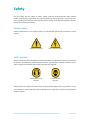
1
Pedal Controlled Application User Manual For Azure Dynamics DMOC Motor Controller MAN-080002-001 DECEMBER 2009 Azure Dynamics Inc. An ISO 9001:2000 Certified Company 9 Forbes Road Woburn, MA USA 01801 T 781.932.9009 F 781.932.9219 [email protected] www.azuredynamics.com Table of Contents Forward.................................................................................................3 Caution..........................................................................................................................................3 Contact Information.....................................................................................................................3 How to Report Errors....................................................................................................................3 Safety....................................................................................................4 Warning Labels..............................................................................................................................4 Safety Symbols..............................................................................................................................4 Overview...............................................................................................5 Application Software...........................................................................6 Pedal Map......................................................................................................................................6 Applications That Do Not Use a 5kΩ Pedal Pot..........................................................................8 Speed Ramps.................................................................................................................................9 Torque Slew Rate Limiting..........................................................................................................10 Power Saver Selector..................................................................................................................11 Safety & Interlocks......................................................................................................................13 Principal Application Variables...................................................................................................14 CAN Status Reporting.................................................................................................................15 Application Parameters..............................................................................................................17 Electrical Interface.............................................................................18 DMOC Interface Kit.....................................................................................................................21 Accelerator Brake Controller—..................................................................................................21 Tri-Power Switch..........................................................................................................................22 Foundation Harness................................................................................................................... 23 Tail Lamp Harness........................................................................................................................24 Troubleshooting and More Details....................................................25 Minimum Connections for Operation........................................................................................25 Speedometer/Tachometer ........................................................................................................25 Regenerative Braking on Brake Pedal Instead of Accelerator Pedal.......................................26 Fault Clearing..............................................................................................................................26 DMOC Variable Capture with ccShell for Troubleshooting......................................................26 MAN-080002-001 DMOC Pedal Controlled Application User Manual, December 2009 Page of 28 Forward Caution The information provided in this manual is intended for use by persons with appropriate technical skills. Any effort to perform repairs to or service your unit without the proper tools or knowledge required for the work can result in personal injury and product damage and will void your warranty! Contact Information Please feel free to call with any suggestions that you may have regarding the content of your manual. If additional service information is needed or to order replacement parts, please call Monday–Friday 8:30am –5:30pm USA Eastern Time: T 781.932.9009 F 781.932.9219 E [email protected] How to Report Errors If, while reading through this manual, you discover an error in the technical information provided, Azure Dynamics asks that you notify its Product Support Department. Please be prepared to provide the following information: — — — — Your name Name and edition of your manual Page number(s) where the error(s) appear Part number and serial number of your unit Information contained in this manual is based on the latest product information available at the time of publication. The right is reserved to make changes at any time without notice. Copyright 2009 Azure Dynamics Inc. All rights reserved. No part of this manual may be reproduced, stored in any retrieval system, or transmitted in any form or by any means (including but not limited to electronic, mechanical, photocopying, and recording) without the prior written permission of Azure Dynamics Inc. This applies to all text, illustrations, tables, and charts. MAN-080002-001 DMOC Pedal Controlled Application User Manual, December 2009 Page of 28 Safety For your safety and the safety of others, please read and understand this entire manual before installing the components you have received from Azure Dynamics. If you have questions regarding the contents of this manual, please call the Azure Dynamics Product Support Department before proceeding. Warning Labels Labels indicate areas in a procedure where you should take appropriate precautions. Labels include: WARNING AND DANGER RISK OF ELECTRIC SHOCK Safety Symbols Always use caution when working on or around any electrical equipment. Wear eye protection at all times. The following symbols will be located in your manual to indicate sections in a procedure where extra caution and/or safety equipment is required. HEARING PROTECTION REQUIRED EYE PROTECTION REQUIRED Always follow any safety instructions that are given at the beginning of a procedure. If you are uncertain as to the safe and proper handling of your equipment, contact Azure Dynamics Product Support. MAN-080002-001 DMOC Pedal Controlled Application User Manual, December 2009 Page of 28 Overview The Azure Dynamics Digital Motor Controller (DMOC445 or DMOC645) is a rugged traction inverter for controlling three-phase AC motors and generators. Flexible software architecture allows for application-specific customization by loading software application modules. These application modules communicate with the motor control core and implement the interface to the higher level controls or directly to the driver inputs and outputs. This manual discusses the “Pedal Controlled” application layer which configures the DMOC to function as a stand-alone traction controller for vehicular applications. In combination with a “DMOC Interface Kit” this application module offers all the functionality for implementing a complete electric vehicle drive. Features include: — Accelerator pedal mapping with detection of short or disconnected wire — Electrical braking with: anti-reverse disable switch battery protections brake light control — Forward/reverse/neutral gear selection — Three-level power selection — Status reporting over CAN (new “FRC” software only) For general information regarding the DMOC, including important safety instructions and warnings, the DMOC445 and DMOC645 User Manual should be consulted which is distributed and revised separately. See Table 1 for the list of relevant manuals. Azure’s PC-based diagnostics/calibration tool ccShell allows the user to access and modify DMOC calibration parameters and to visualize and capture signals and variables in real time. (Calibration parameters have EE1, EE2 or EEX prefixes. Variables have EE3, ISR or FRC prefixes). While the meanings of the most important calibrations and signals of the DMOC core are described in this document, the reader is referred to the ccShell User Manual for information on how to install and use this tool. Table 1: List of Relevant Manuals Document Name Document Number DMOC445 and DMOC645 User Manual MAN-080001 Pedal Controller Application User Manual MAN-080002 CAN Controlled Application User Manual MAN-080003 ccShell User Manual Please note, this manual is distributed as part of the ccShell software. It is available under ccShell’s “Help” menu.) MAN-080008 MAN-080002-001 DMOC Pedal Controlled Application User Manual, December 2009 Page of 28 Application Software Pedal Map The accelerator pedal position is mapped to a desired torque as described here. The map itself is configurable by parameter calibration. Three valid zones can be distinguished (for better readability, the EEX parameter prefixes of the parameter names are omitted in Figure 1): HIGH_ERROR ACCEL NEUTRAL BRAKE LOW_ERROR Pedal Mode MaxAccelTorque PedHi PedMax PedAccel PedZero PedLo PedBrake Torque FRC.PedalS MaxBrakeTorque Figure 1: Pedal Torque Map Fault Zones: The red zones indicate fault zones. If the pedal input is shorted, high or low, zero torque is produced. Any pedal values below PedLo (hard coded at 0.01) or above PedHi (hard coded at 0.9) are consider to be a pedal fault (short or open) and will result in no torque. Brake Zone: The first zone of the pedal is used to control regenerative braking. It ranges from PedLo (fixed) to EEXPedBrake. Full torque (EEXMaxBrakeTorque) is applied when the accelerator pedal is not depressed at all. As the pedal is depressed past EEXPedZero, the brake torque is ramped down linearly. Coast or Neutral Zone: The torque is zero in the second zone, which is delimited by EEXPedBrake and EEXPedAccel. Accel Zone: Past EEXPedAccel, the torque is ramped up as the pedal is depressed. The torque reaches its maximum value (EEXMaxAccelTorque) at EEXPedMax. Table 2 summarizes the variable FRC.PedMode. MAN-080002-001 DMOC Pedal Controlled Application User Manual, December 2009 Page of 28 Table 2: FRC.PedMode Variable Variable: FRC.PedMode State Value Name Description 0 NEUTRAL Vehicle is in neutral or pedal position is in coast zone 1 ACCEL Vehicle is in FWD or REV and pedal position is in accel zone 2 BRAKE Vehicle is in FWD or REV and pedal position is in brake zone 3 reserved 4 LOW_ERROR Pedal is shorted to GND 5 HIGH_ERROR Pedal is shorted to +Vcc In some vehicles, a strong feedback between the vehicle’s motion and the driver’s foot exists. It can lead to unwanted oscillations and may cause serious drivability problems. An effective method to break the resonance is to add a dead band to the position sensing; this is illustrated in Figure 2. If the driver’s foot oscillates within the dead band, no change in the measured pedal position is made and the drive torque remains constant. The position of the pedal can be viewed by means of the variable FRC.PedalS. The pedal position FRC.PedalS is a normalized variable (0-1) derived from the voltage of the 5kΩ pedal potentiometer. The pedal map parameters are listed in Table 3. Table 3: Pedal Map Parameters Parameter Description EEXMaxAccelTorque Maximum acceleration torque when pedal is fully depressed EEXMaxBrakeTorque Maximum braking torque when pedal is fully released EEXPedBrake Pedal value below which braking torque begins to be applied EEXPedZero Pedal value below which max braking torque (EEXMaxBrakeTorque) is applied EEXPedAccel Pedal value above which acceleration torque begins to be applied EEXPedMax Pedal value above which max acceleration torque (EEXMaxAccelTorque) is applied EEXPedHyst Hysteresis value for pedal input (pedal position needs to change by more than EEXPedHyst to be recognized as a valid new position) Raw Pedal Position Pedal Position Figure 2: Pedal Dead Band MAN-080002-001 DMOC Pedal Controlled Application User Manual, December 2009 Page of 28 Applications That Do Not Use a 5kΩ Pedal Pot Figure 3 and Figure 4 below are provided as a reference for applications that do not use a 5kΩ pedal pot. The circuit schematic in Figure 3 shows the pullup and pulldown resistors (inside the DMOC) that are associated with the PEDAL_HI and PEDAL_LOW outputs. Note that VCC_A is 3.3V. The circuit schematic in Figure 4 shows that the ACCEL_PEDAL input of the DMOC is pulled down to “ground” by a 100kΩ resistor, and the signal then passes through a unity gain buffer. Please note, though these schematics are accurate as of this writing, they are subject to change and therefore should be used for reference only. VCC_A 3.3V 1.82K PEDAL_HI 150 PEDAL_LO 150 BRAKE_LO PEDAL_HI PEDAL_LO BRAKE_LO Figure 3: Pullup/pulldown resistors inside DMOC associated with PEDAL_HI/PEDAL_LOW outputs. 3.3V 3.3V 100nF ACCEL_PEDAL 200 + _ ACCEL_PEDAL_BUF 100K Figure 4: ACCEL_PEDAL input of DMOC pulled to “ground” by 100kΩ resistor, then passed through unity gain buffer. MAN-080002-001 DMOC Pedal Controlled Application User Manual, December 2009 Page of 28 Speed Ramps Several ramps are implemented to reduce and limit the drive torque corresponding to vehicle speed. These ramps prevent the vehicle from over speeding, both in reverse (for safety) and in forward (for motor protection). The overspeed protection ramps are illustrated in Figure 5. The acceleration parameters are listed in Table 4. During regenerative braking, the brake torque must be reduced to zero before the vehicle starts reversing its direction. These ramps are illustrated in Figure 6. Similar to the pedal map, the speed ramps are configurable by means of parameter calibration; the parameters themselves are listed in Table 5. FullAccelPosSpeed NoAccelNegSpeed FullAccelNegSpeed (forward) NoAccelPosSpeed Acceleration Torque Speed (reverse) Figure 5: Speed Ramps under Acceleration Table 4: Acceleration Parameters Parameter Description EEXFullAccelPosSpeed Positive (forward) motor speed up to which full acceleration torque (EEXMaxAccelTorque) is allowed EEXNoAccelPosSpeed Positive (forward) motor speed above which acceleration torque is zero EEXFullAccelNegSpeed Negative (reverse) motor speed up to which full acceleration torque (EEXMaxAccelTorque) is allowed EEXNoAccelNegSpeed Negative (reverse) motor speed above which acceleration torque is zero Note: Torque is linearly ramped between EEXFullAccelPosSpeed and EEXNoAccelPosSpeed, and between EEXFullAccelNegSpeed and EEXNoAccelNegSpeed. NoBrakeSpeed FullBrakeSpeed (reverse) FullBrakeSpeed NoBrakeSpeed Brake Torque Speed (forward) Figure 6: Speed Ramps When Braking MAN-080002-001 DMOC Pedal Controlled Application User Manual, December 2009 Page of 28 In order to avoid oscillations around the EEXNoBrakeSpeed point, a hysteretic loop is implemented as shown in Figure 7. The parameters are listed in Table 5. As the vehicle slows down under regenerative braking past EEXFullBrakeSpeed, the torque is reduced linearly with speed. Once the vehicle speed drops below EEXNoBrakeSpeed, regenerative braking is completely disabled, until the vehicle re-accelerates past EEXRegenOnSpeed. This method has proven to be successful in avoiding brake torque oscillations at very low speeds. The regen state variable, FRC.RegenState takes the values in Table 6 and can be viewed with ccShell. Table 5: Regen Parameters Motor speed (both positive and negative) above which full braking torque (EEXMaxBrakeTorque) is applied. EEXNoBrakeSpeed Motor speed (both positive and negative) below which regen braking is completely disabled EEXRegenOnSpeed Motor speed (both positive and negative) above which regen braking is re-enabled Brake Torque RegenOnSpeed Description EEXFullBrakeSpeed NoBreakSpeed Parameter Speed (forward) Figure 7: Hysteretic Loop around EEXNoBrakeSpeed Table 6: Regen State Values Variable: FRC.RegenState (formally called ISR2RegenState) State Name Description 0 POWERUP Regenerative braking feature not yet initialized 1 DISABLED Regenerative braking feature is disabled 2 ENABLED Regenerative braking feature is enabled 3 FAULT Regenerative braking feature has a problem Torque Slew Rate Limiting To improve drivability, it is necessary to limit the rate of change of the motor torque (also known as slew rate). The application software provides several parameters to tune the slew rates as shown in Table 7. Table 7: Slew Rate Parameters Parameter Description EEXTorqueSlew Slew rate limit on torque set point in acceleration mode EEXBrakeTorqueSlew Slew rate limit on torque set point in braking mode EEXUnloadSlew Slew rate when reducing torque while preserving torque sign MAN-080002-001 DMOC Pedal Controlled Application User Manual, December 2009 Page 10 of 28 Specific positive and negative slew rates are applied based on the torque level (divided into four zones) as shown in Table 8. Table 8: Torque Slew Rate Parameters Logic Initial Torque Value Increasing Torque Decreasing Torque EEXPreloadTorque < Torque EEXTorqueSlew EEXUnloadSlew 0 < Torque < EEXPreloadTorque EEXTorqueSlew EEXTorqueSlew -EEXPreloadTorque < Torque < 0 EEXBrakeTorqueSlew EEXBrakeTorqueSlew Torque < -EEXPreloadTorque EEXBrakeTorqueSlew EEXUnloadSlew A graphic representation of the torque slew rate limits is shown in Figure 8. Torque EEXUnloadSlew EEXPreloadTorque EEXTorqueSlew Time EEXTorqueSlew 0– EEXBrakeTorqueSlew -EEXPreloadTorque EEXBrakeTorqueSlew EEXTorqueSlew EEXBrakeTorqueSlew EEXUnloadSlew Figure 8: Torque Slew Rate Limits Power Saver Selector The battery power limit for acceleration is selectable by means of the “Tri-Power Switch” (part of the optional “DMOC Interface Kit”) which is connected to the “Power Saver” input. The “Power Saver” is an analog input mapped into three zones, as depicted in Figure 9. The power level is determined based on the user input resistance Rp and the threshold values R1 and R2 discussed further below. Note that the resistance with key off for Econ (max range) must be less than the resistance with key off for Normal, which must be less than the resistance with key off for Power (max power). In most circumstances, especially if the customer is using Azure’s DMOC interface kit, no adjustment will be necessary. Power Limit Max Range or Economy EEXMaxAccelPower Normal Max Power EEXNormAccelPower EEXMinAccelPower R1 R2 Pos1 Pos2 Resistance (Rp) % Position (0-1) Figure 9: Power Saver Zones, based on power saver resistance input MAN-080002-001 DMOC Pedal Controlled Application User Manual, December 2009 Page 11 of 28 The Power level is determined by the resistance provided across the power saver input, as shown in Figure 10. The equation for the voltage divider circuit for the power saver potentiometer is: Rp = Position (0-1,normalized %) (Rp + 5KΩ) where Rp is the resistance across the power saver switch (i.e. the user input across pins 15 and 16 of the DMOC 35-pin connector). 5kΩ Powersaver Rp (below voltage divider) Gnd inside DMOC outside DMOC Figure 10: Voltage Divider Circuit for Power Saver Potentiometer The Power Saver zones are shown in Table 9, and the power levels can be adjusted by the calibrations there. Table 9: Power Saver Zones Variable: FRC.PowerSaverSel State Name Description 1 MAX_POWER EEXMaxAccelPower is the selected power limit 2 NORM_POWER EEXNormAccelPower is the selected power limit 3 MIN_POWER EEXMinAccelPower is the selected power limit Power Saver Thresholds: The zone thresholds (R1 and R2 in Figure 9) default to 3.8kΩ and 8.15 kΩ, respectively. The resistance across the power saver input (pins 15 and 16 on the DMOC 35-pin connector) determines the power saver setting as follows: Max Range: Normal: Max Power: Rp < 3.8 kΩ 3.8 kΩ < Rp < 8.15 kΩ 8.15 kΩ <Rp These thresholds are not adjustable in software released before April 2008 (including “1631”). MAN-080002-001 DMOC Pedal Controlled Application User Manual, December 2009 Page 12 of 28 Adjustable Zone Thresholds: The adjustable zone thresholds are a new feature implemented in the “FRC” software release, starting in April 2008. The zone thresholds are controlled via calibration of the parameters in Table 10. Calibration instructions are below. Table 10: Power Saver Calibration Parameter Description EEXPowerSaverPos1 Below this threshold the PowerSaver mode is MIN_POWER EEXPowerSaverPos2 Above this threshold the PowerSaver mode is MAX_POWER Adjusting Tri-Power Switch Resistances in “FRC” Software In FRC software, if the default resistances for the tri-power switch thresholds are incorrect for your application, they can be adjusted in software using ccShell, based on position (ISR1PowerSaver). The two ccShell parameters involved are EEXPowerSaverPos1 and EEXPowerSaverPos2. The default values for EEXPowerSaverPos1 and EEXPowerSaverPos2 are 0.42969 and 0.61914, respectively (corresponding to the default resistances specified above). Example of correction if the resistances are not within the ranges above, for FRC software only: Tri-power switch setting Measure key off resistance (Rp) Calculate Rp ÷ (Rp + 5kΩ) Change EEXPowerSaverPos1 Econ (max range) 1.56 kΩ 0.24 Normal 2.29 kΩ 0.31 currently 0.42969, needs to be between 0.24 and 0.31 Power (max power) 5.42 kΩ 0.52 Change EEXPowerSaverPos2 currently 0.61914, needs to be between 0.31 and 0.52 Safety & Interlocks Shutdown/Disconnect For a shutoff, it is recommended that the 12V be disconnected. Removing the 12V power will immediately disable the DMOC power supply and shut the unit down. For additional safety, it is recommended that an emergency high voltage disconnect be provided as well; however, this should be a normally closed switch that is only actuated in emergencies or for maintenance. If a contactor is used as a HV disconnect, it could interfere with the operation of the DMOC’s internal contactor, resulting in excessively long precharge times, or damage the DMOC. Interlocks At power up, the DMOC will remain disabled as long as either the accelerator pedal is depressed or the gear switch is in forward or reverse. This is a startup safety interlock; you must have zero torque request and be in neutral for the DMOC to power up and enable. Startup order of operation/sequence: — Contactor must close — Powerstage must advance to READY For these events to occur there are a few application—specific interlocks described here, which are required in addition to the requirements documented in the DMOC445 and DMOC645 User Manual: MAN-080002-001 DMOC Pedal Controlled Application User Manual, December 2009 Page 13 of 28 Contactor Interlock: — ISR2DriveEnabled = TRUE (or bypass with EEXNoIgnSwitch, see below), and — FRC.CarDirectionSwitch = NEUTRAL Power Stage Interlocks Required for READY, indicated by ISR2PowerStageStateInfo = WAITING_FOR_APPLICATION_CODE_INTERLOCK: — Pedal not depressed (Pedal position less than EEXPedZero). Power Stage Fault acknowledge interlock, indicated by ISR2PowerStageStateInfo = WAITING_FOR_FAULT_ACKNOWLEDGE — Pedal not depressed (Pedal position less than EEXPedZero), and — No torque is requested. To command torque and spin the motor FRC.CarDirectionSwitch = FORWARD or REVERSE Pedal depressed (Pedal position more than EEXPedAccel). The DMOC also has a “drive enable” and a “drive disable” signal (digital inputs) which are both active low (i.e. need to be pulled to GND to be active). For the DMOC to enable, drive enable has to be active and drive disable needs to be passive (i.e. not pulled to GND). If the “drive enable” feature is not desired, it can be switched off by setting the calibration parameter EEXNoIgnSwitch to 1. Grounding “drive disable” will always result in disabling the DMOC; this is often used as a charger interlock. Table 11: Drive Enable-Disable Parameter Parameter Description EEXNoIgnSwitch 0 = ISR2DriveEnabled depends on “drive enable” 1 = ISR2DriveEnabled=TRUE (“drive enable” ignored) Principal Application Variables Table 12 shows the most frequently viewed application variables. Refer to the DMOC445 and DMOC645 User Manual for information about other important DMOC variables. Table 12: Principal Application Variables Variable Description FRC.CarDirectionSwitch Reverse (-1), Neutral (0), Forward (1) FRC.FinalTorqueDesired* Torque command after limits are imposed (same as ISR2TorqueDesired) FRC.GearInterlock Interlock based on pedal position and vehicle speed to enable transition between forward and reverse. FRC.MaxAbsTorqueBySpeed* Torque available based on speed (1= no derating, 0 = fully derated) FRC.PedalS Pedal Input reading (0-1), replaced ISR2PedalS FRC.PedMode Pedal zone indicator (acceleration, neutral, or braking) FRC.PedTorqueDesired* Torque request based on pedal position FRC.PowerSaverSel Selection of power-level FRC.RegenState Regenerative braking finite state machine indicator (formerly ISR2RegenState) FRC.SpeedLimit Torque limiting based on speed (0-1) ISR2PedalS Replaced by FRC.PedalS ISR1PowerSaver* Power saver potentiometer position, Azure internal use only ISR2PowerSaverSel Selection of power-level; replaced by FRC.PowerSaverSel ISR2SpeedLimit Torque limiting based on speed (0-1), replaced by FRC.SpeedLimit MAN-080002-001 DMOC Pedal Controlled Application User Manual, December 2009 Page 14 of 28 CAN Status Reporting While this application does not receive any command messages over CAN, it may be enabled to report status for use in vehicle displays. Setting the parameter EEXCANTxEnabled = 1 enables sending of all status messages. Three status messages are available with the contents defined in Table 13. The CAN ID and transmit rate of each message may be individually configured, using the CAN parameters defined in Table 14. General CANbus settings are documented in the DMOC445 and DMOC645 User Manual. Table 13: DMOC Status Messages Over CAN Message Temperature Status Message EEXCANTempStatusID Rate (sec) 1 EEXCANTempStatusCycleSec DLC 8 Format standard Direction tx Endian big Byte Signal Name Min Max Res Units Width Offset Details 0 motor stator temperature -40 200 1 C 8 -40 based on ISR2MotorLimit (see 1 inverter temperature -40 200 1 C 8 -40 ISR2HeatsinkTemp 2,3,4,5 reserved 6 CAN interface level 0 240 1 n/a 8 0 FRC_CAN_REV 7 rolling counter 0 255 1 n/a 8 0 Value increments with each Message Mechanical Status Message EEXCANMechStatus1ID Rate (sec) 0.02 EEXCANMechStatus1CycleSec DLC 8 Format standard Direction tx Endian big Byte Signal Name Min Max Res Units Width Offset Details 0,1 motor torque actual -3000 3000 0.1 Nm 16 -3000 ISR2RealTorque 2,3 motor speed actual -20000 20000 1 rpm 16 -20000 ISR2HertzWF 4 powerstage state 0 240 1 n/a 8 0 ISR2PowerStageState 5 active fault (enum) 0 240 1 n/a 8 0 ISR2PSFaultActive (see DMOC445 6 status code 0 255 1 n/a 8 0 7 reserved note below) message to show DMOC is alive and DMOC645 User Manual) ISR2StatusCode (see DMOC445 and DMOC645 User Manual) Message Electrical Status Message EEXCANElecStatus1ID Rate (sec) 0.02 EEXCANElecStatus1CycleSec DLC 8 Format standard Direction tx Endian big Byte Signal Name Min Max Res Units Width Offset Details 0,1 DC battery voltage 0 1000 0.1 V 16 0 ISR2BatVoltageWF 2,3 DC current -500 500 0.1 A 16 -500 ISR2EstBatCurrent 4 thermal limit cause 0 240 1 n/a 8 0 ISR2ThermCurrentLimitCause 5,6,7 reserved MAN-080002-001 DMOC Pedal Controlled Application User Manual, December 2009 Page 15 of 28 Note that the Motor Temperature Sensor is a PTC designed to protect the motor, not provide a actual temperature feedback. The “temperature” reported over CAN is only intended to indicate if a problem exists, therefore, only three discrete values are provided: 20C if the temperature is OK and the motor can operate normally, 120C if some thermal derating is taking place and 200C if the motor is over temperature and completely thermal limited. Note that ISR2BatVoltageWF is the filtered battery voltage, and is approximately equal to ISR2BatVoltage. Note, all these messages are Big Endian Format (Motorola, most significant byte first) and all signed values have offsets equal to their maximum negative value. To find the desired value in the units you expect, take the raw value over CAN, multiply by the resolution and add the offset. Example of Parsing a Temperature Signal: Looking at a temperature signal, for example the inverter temperature, with a range -40C to 200C with a resolution of 1C and offset of -40C, the following table has some example conversions: Hex Value Decimal Value Temperature 0x00 0 -40C 0x3C 60 20C 0xF0 240 200C 0xF1-0xFF 241-255 Error, invalid data Example of Parsing the Mechanical Status Message: For example, on startup the Mechanical Status Message content might read as follows: 75 30 4e 20 01 00 23 ff Bytes 0 and 1 (0x7530) indicate zero torque ( 0x7530 = 30000 and 30000*0.1 – 3000 = 0 Nm). Bytes 2 and 3 (0x4e20) indicate zero speed (0x4e20 = 20000 and 20000*1 – 20000 = 0 RPM). Byte 4 shows the PowerStageState at 1 (READY). Byte 5 shows there are no active errors. Byte 6 shows the Status Code of 0x23 (hex) which corresponds to 00100011 (binary), which, as shown in the DMOC445 and DMOC645 User Manual, indicates the contactor is closed, power stage is ready, more torque and power are available. Note that bit 5 (the thermal limit active signal) is not relevant in the READY state. Table 14: Application Specific CAN Parameters Variable Description EEXCANElecStatus1ID Electrical Status Message CAN ID EEXCANElectStatus1CycleSec Transmit rate for Electrical Status Message in seconds EEXCANMechStatus1ID Mechanical Status Message CAN ID EEXCANMechStatus1CycleSec Transmit rate for Mechanical Status Message in seconds EEXCANTempStatusID Temperature Status Message CAN ID EEXCANTempStatusCycleSec Transmit rate for Temperature Status Message in seconds EEXCANTxEnabled Set to 1 to enable status reporting of all messages. If set to zero, only the mechanical status message will be transmitted at a low frequency to indicate the DMOC is alive. MAN-080002-001 DMOC Pedal Controlled Application User Manual, December 2009 Page 16 of 28 All CANIds are displayed as decimal numbers in ccShell. Many CAN tools work more naturally in hex, so note, for example, the default Mechanical Status ID of 577 in decimal = 0x241 in hex. Application Parameters Table 15 summarizes the most frequently used application parameters. Please refer to the DMOC445 and DMOC645 User Manual for information about other important DMOC parameters. Table 15: Frequently Used Pedal Control Application Parameters. Variable Description EEXMinAccelPower Acceleration power limit (Max Range setting on tri-power switch) EEXNormAccelPower Acceleration power limit (Normal setting on tri-power switch) EEXMaxAccelPower Acceleration power limit (Max Power setting on tri-power switch) EEXMaxRegenPower Regen power limit EEXNoIgnSwitch Can be used to force drive enable EEXPedAccel Acceleration begins above this pedal position EEXPedBrake Regen begins below this pedal position EEXPedHyst Pedal dead band EEXPedMax Full acceleration torque above this pedal position EEXPedZero Full regen torque below this pedal position EEXRegenOnSpeed Speed above which regen is enabled EEXFullBrakeSpeed Speed above which full regen is possible EEXNoBrakeSpeed Speed below which no regen is possible EEXAccelMaxTorque Maximum allowable acceleration torque EEXBrakeMaxTorque Maximum allowable brake torque EEXBrakeTorqueSlew Slew rate limit to brake torque EEXInterlockSpeedHigh Speed above which shifting is disabled (except for going to neutral) EEXInterlockSpeedLow Speed below which shifting is interlocked with zero accelerator pedal input EEXBrakeLightOffTorque Torque below which the brake lights are turned off EEXBrakeLightOnTorque Torque above which the brake lights are switched on EEXFullAccelPosSpeed Maximum forward speed allowing full acceleration torque EEXFullAccelNegSpeed Maximum reverse speed allowing full acceleration torque EEXTorqueSlew Slew rate limit to torque when accelerating EEXUnloadTorqueSlew Slew rate limit in unload zone MAN-080002-001 DMOC Pedal Controlled Application User Manual, December 2009 Page 17 of 28 Electrical Interface Besides the high voltage connections, which are documented in the DMOC445 and DMOC645 User Manual, a number of low voltage signals are used for the “Pedal Controlled” application module. The 12V auxiliary supply needs to be able to source 10A of current and must be protected by a 15A fuse. The auxiliary supply also acts as an enable signal for the internal power supply of the DMOC. In other words, a DMOC requires 12V to be present in order to operate. Three connectors exist on the side of the DMOC: — 14 pin AMPSeal: For the motor speed-sensor cable (dedicated connector) — 8 pin AMPSeal: For RS-232 and CAN communications — 35 pin AMPSeal: Application interface connector It is recommended that an Azure Dynamics “DMOC Interface Kit” be used for the connections of the pedal and control switches; however, it is also possible to implement a customized interface harness and use custom controls. Note that all GND connections are at a common potential. For noise immunity, they should not be tied to vehicle ground (i.e. external to the DMOC). The exception to this is pin 13 on the DMOC 35-pin connector, which should be connected to 12V chassis ground. Both the backup light and brake light signals are isolated from the DMOC GND and vehicle ground. They should be used in conjunction with a voltage source that is referenced to vehicle ground (for example the vehicle 12V battery). The signals are capable of sinking / sourcing 5A and should be fused externally with a 5A fuse. If more current is needed, then external relays with built-in free-wheeling diodes should be used. Such relays can be purchased from Panasonic or Bosch. The power saver internal circuitry is pulled up to 3.3V through a 4.99kΩ resistor. The internal circuitry for forward and for reverse is pulled up to 3.3V through a 10kΩ resistor. Please see Figure 11 for the Azure Dynamics DMOC Foundation Harness (part of the Azure Dynamics DMOC Interface Kit; mates to 35 pin connector) wiring diagram. Figure 12 shows a suggested customer interface. Please note, some existing versions of the DMOC Foundation Harness may not have pins 30 and pins 23 and 12 populated on the mating DMOC 35-pin connector. Also, existing versions of the Foundation Harness do not include the back-up light relay. If you need assistance, please ask your Azure Dynamics or distributor contact. MAN-080002-001 DMOC Pedal Controlled Application User Manual, December 2009 Page 18 of 28 AMPSEAL 35-PIN BRAKE LIGHTS WEATHERPACK 4M 14 R BRAKE_LT_SINK 24 BK BAKUP_LT_SRC 23 R BAKUP_LT_SINK 12 BK DRIVE_DISABLE 08 W A DRIVE_DISABLE DIG_GND 19 BK B DIG_GND SPEEDO_OUT 25 W KEYED_12V_SRC 01 R A KEYED_12V_SRC KEYED_12V_SINK 13 BK B KEYED_12V_SINK PEDAL_LO 06 BU/W A PEDAL_LO ACCEL_PEDAL 03 W B ACCEL_PEDAL PEDAL_HI 28 W/BK C PEDAL_HI ANA_GND 05 G 02 ANA_GND POWER_SAVER 15 G/BK 03 POWER_SAVER FORWARD 29 R/W 1 FORWARD DIG_GND 20 BU 2 DIG_GND REVERSE 18 G/W 3 REVERSE REGEN_DISABLE 07 R 01 REGEN_DISABLE DIG_GND 35 BK 02 DIG_GND DRIVE_ENABLE 30 BRAKE_LT_SRC C BRAKE_LT_SRC D BRAKE_LT_SINK A BAKUP_LT_SRC B BAKUP_LT_SINK BACK-UP LIGHTS DRIVE DISABLE SPEEDO WEATHERPACK 2F WEATHERPACK 1M A 12V ACCEL PEDAL SPEEDO_OUT WEATHERPACK 2M WEATHERPACK 3F AMP 3F POWER SAVER MOLEX 3M FORWARD/REVERSE AMP 2F REGEN DISABLE DRIVE ENABLE O UNTERMINATED BK DMOC UNTERMINATED Figure 11: DMOC I/O Interface Harness (Foundation Harness) MAN-080002-001 DMOC Pedal Controlled Application User Manual, December 2009 Page 19 of 28 NOTE: Vehicle brake and reverse lights wiring will vary. Diagram is provided for reference only. K1 WEATHERPACK 4F BRAKE_LT_SRC C BRAKE_LT_SINK D BAKUP_LT_SRC A BAKUP_LT_SINK B WEATHERPACK 2M DRIVE_DISABLE A DIG_GND B WEATHERPACK 1F SPEEDO_OUT BRAKE LIGHTS 30 87 85 86 BRAKE LIGHTS BACK-UP LIGHTS K2 30 87 85 86 BACK-UP LIGHTS DRIVE DISABLE SW2 SPEEDO A WEATHERPACK 2F KEYED_12V_SRC A KEYED_12V_SINK B WEATHERPACK 3M PEDAL_LO A ACCEL_PEDAL B PEDAL_HI C AMP 3M 12V F1 SW1 B1 12V ACCEL PEDAL R1 5K POWER SAVER ANA_GND 02 POWER_SAVER 03 R2 2.2K SW3 MAX RANGE MAX POWER NORMAL MOLEX 3F R3 1.8K FORWARD/REVERSE FORWARD 1 DIG_GND 2 REVERSE 3 SW4 AMP 2M 01 DIG_GND 02 NEUTRAL REVERSE REGEN DISABLE REGEN_DISABLE FORWARD DRIVE ENABLE SW5 SW6 NOTE: Splice directly to the wires or add a connector of your choice. Legend F1 12VDC Fuse, 15A K1 Brake Lights Relay K2 Back-up Lights Relay SW1 Ignition Key Switch SW2 Drive Disable Switch SW3 Power Saver Switch, 3 Position SW4 Forward/Reverse Switch, 3 Position SW5 Regen Disable Switch SW6 Drive Enable Switch R1 Accelerator Pedal Potentiometer, 5K R2 Resistor, 2.2K R3 Resistor, 1.8K B1 12VDC Battery Figure 12: Suggested DMOC Customer Interface I/O MAN-080002-001 DMOC Pedal Controlled Application User Manual, December 2009 Page 20 of 28 DMOC Interface Kit The Azure Dynamics DMOC Interface Kit consists of the following items: — — — — Accelerator / Brake Controller (ABC) Tri-Power Switch Foundation Harness Tail Lamp Harness (note, older versions include only the Regen Brake Harness) Note, the accelerator pedal is NOT included. Any pedal that works with a 5kΩ pot is acceptable. Accelerator Brake Controller The DMOC is designed for a 5kΩ linear pedal pot, which is part of the Accelerator Brake Controller in the Azure Dynamics DMOC Interface Kit, please see Figure 13. A pot with a different range can be used, but it needs to be calibrated using the pedal map; please see Figure 3 and Figure 4. The 5kΩ linear pot is a variable resistor being used as a voltage divider. All pots, including this one, have three wires, but sometimes all three aren’t used. In the Azure Dynamics pot, Pin 3 is the wiper, Pin 28 is Pedal High, and Pin 6 is Pedal Low. Azure specifies a 5kΩ pot and does not recommend the use of pedals which have a voltage output. Figure 13: Accelerator Brake Controller (ABC-1) MAN-080002-001 DMOC Pedal Controlled Application User Manual, December 2009 Page 21 of 28 Tri-Power Switch The Tri-Power Switch implements several functions: — — — — — — Fwd/Rev Switch Battery Power Selection (Max Power, Normal, Max Range) Disable switch for electric braking (regen) Reverse light control Back-up light control Cabin heater control Please see Figure 14. Note that the three wires to the heat switch, the one reverse lamp connector, regen disable and the one neutral interlock connector are not needed for DMOC operation. Output to Heater Relay (12 Volts When Switch is On) 12 Volt Input to Heat Switch Heat Switch Ground Lug Regenerative Braking Disable (Closed for No Regen) Neutral Interlock (Not Connected to DMOCs) Forward and Reverse Output Reverse Lamp Output Closed in Reverse Power Level Output Figure 14: Tri-Power Switch MAN-080002-001 DMOC Pedal Controlled Application User Manual, December 2009 Page 22 of 28 Foundation Harness The Foundation Harness provides the wiring between the connections between the DMOC and the other Interface Kit Components. See Figure 15 and Figure 16. The wiring diagram for the Foundation Harness is shown in Figure 11 and Figure 12. Figure 15: Foundation Harness Figure 16: Tri-Power Switch and Pedal Connections Besides the connections to the Tri-Power Switch and the accelerator pedal (note, pedal is not included in Interface Kit) shown in Figure 16, the following connections are made: — Keyed 12 volt: Black is ground, Red is + 12 volts — Speedometer Output: Optional. See Troubleshooting and More Details. — Charger Interlock: Optional. This keeps the vehicle from being driven while the charger is connected. Closing (connecting the white wire to the black wire) this interlock will keep the DMOC from driving the motor. MAN-080002-001 DMOC Pedal Controlled Application User Manual, December 2009 Page 23 of 28 Table 16 summarizes the wiring of the Azure Dynamics Foundation Harness; see also the 35-Pin Connector Pinout information in the DMOC445 and DMOC645 User Manual. Table 16: Azure Dynamics Foundation Harness Wiring Signal Source Connector Pin Cable Recommendation Color/ Stripe Destination Connector Pin REGEN_DISABLE AMP35 7 22AWG 15 cond grey shielded red AMP2F Plug 1 GND_D AMP35 35 22AWG 15 cond grey shielded black AMP2F Plug 2 POWER_SAVER AMP35 15 22AWG 15 cond grey shielded green / black AMP3F Plug 3 GND_A AMP35 5 22AWG 15 cond grey shielded green AMP3F Plug 2 FORWARD- AMP35 29 22AWG 15 cond grey shielded red / white Molex 3M Intl Plug 1 REVERSE- AMP35 18 22AWG 15 cond grey shielded green / white Molex 3M Intl Plug 3 GND_D AMP35 20 22AWG 15 cond grey shielded blue Molex 3M Intl Plug 2 SPEEDO_BUF AMP35 25 22AWG 15 cond grey shielded white Weatherpack 1M A KEYED_12V_SRC AMP35 1 18AWG 2 cond grey red Weatherpack 2M A KEYED_12V_SINK AMP35 13 18AWG 2 cond grey black Weatherpack 2M B PEDAL_LO AMP35 6 22AWG 15 cond grey shielded blue / white Weatherpack 3F A ACCEL_PEDAL AMP35 3 22AWG 15 cond grey shielded white Weatherpack 3F B PEDAL_HI AMP35 28 22AWG 15 cond grey shielded white / black Weatherpack 3F C DRIVE_DISABLE- AMP35 8 20AWG 2 cond grey shielded white Weatherpack 2F A GND_D AMP35 19 20AWG 2 cond grey shielded black Weatherpack 2F B BRAKE_LT_SRC AMP35 14 18AWG 2 cond grey red Weatherpack 4M C BRAKE_LT_SINK AMP35 24 18AWG 2 cond grey black Weatherpack 4M D BACKUP_LT_SRC AMP35 23 18AWG 2 cond grey red Weatherpack 4M A BACKUP_LT_SINK AMP35 12 18AWG 2 cond grey black Weatherpack 4M B Important: None of the GND_D and GND_A pins should be connected to vehicle chassis (i.e. external to the DMOC). Tail Lamp Harness The Tail Lamp Harness is illustrated in Figure 17. 12 Volt Supply 12 Volt Switched Brake Ground Ground 12 Volt Switched Reverse 12 Volt Supply Figure 17: Tail Lamp Harness MAN-080002-001 DMOC Pedal Controlled Application User Manual, December 2009 Page 24 of 28 Troubleshooting and More Details Minimum Connections for Operation The DMOC requires (in order) 1. 2. 3. 4. high voltage connected inside the junction box 12 volts on pin 1 on 35-pin connector ground pin 13 on 35-pin connector to the 12V return connect pins 19 and 29 on 35-pin connector to each other The DMOC should power up and spin the motor once the pedal is pressed. However, pins 19 and 29 cannot be left connected (Step 4 provides a “forward” request.) This is because the DMOC contactor needs to close and then the DMOC needs to see a neutral signal and then a forward signal each time the DMOC is power-cycled. Please refer also to the “Safety and Interlocks” section of this manual. Speedometer/Tachometer The DMOC has a frequency-modulated 12V push-pull output (open-emitter gauge drive) that can drive some speedos/tachs. Azure has had success with the Continental (was Siemens) VDO, “Cockpit Series”, 85mm diameter, wired to work with “electronic transmissions”. This output is Pin 25 from the DMOC 35-pin connector, marked on the Azure Foundation Harness in the Azure DMOC Interface Kit. Speedometer Installation and Operation Instructions (Download PDF) http://usa.vdo.com/generator/www/us/en/vdo/main/products_solutions/cars/performance_instruments/vdo_performance_instruments/instrument_series/cockpit/speedometers/download/flc_0515012051programmablespeedometer_en.pdf The DMOC parameter called EE1SpeedoDiv can be adjusted for specific speedos/tachs. However, every speedo/tach is different and the software isn’t designed to work with all of them. To calibrate EE1SpeedoDiv: — — — — — — — Connect speedo output to speedometer Calculate km/h corresponding to 2500 rpm at the motor Don’t spin the motor during the calibration process Set EE1SpeedoDiv = -100, speedometer should move If reading is higher then km/h calculate above, make the number more negative (e.g. -110) If reading is lower then km/h calculate above, make the number less negative (e.g. -90) Once the speedometer displays the correct speed, flip the sign of EE1SpeedoDiv (make it a positive number) — Now drive the vehicle and double-check speedometer calibration The equation for the speedo is 2 × rpm ÷ EE1SpeedoDiv ≈ speedo output frequency. MAN-080002-001 DMOC Pedal Controlled Application User Manual, December 2009 Page 25 of 28 Regenerative Braking on Brake Pedal Instead of Accelerator Pedal Azure Dynamics’ system normally has regenerative braking on the accelerator pedal. Some customers have expressed interest in moving regen to the brake pedal. The regen brake light switch can be tied into the Regen Disable signal (using a relay) so that regen comes on only when the accelerator pedal has been released and the brake pedal has been pressed. This is the reverse of having the controller turn on the brake lights when you release the accelerator. This change actually reverses the function of the regen relay. In the Azure Dynamics DMOC Interface Kit, the regen brake light relay turns on the brake lights when the DMOC is in regen mode. With this modification, the regen relay is eliminated and replaced with a similar (but normally closed) relay to activate the regen function when the brake lights come on. A normally closed relay would need to be installed so that when the brake lights come on, the relay opens up and lets the regen circuit activate on the DMOC. Fault Clearing Most DMOC faults are cleared by releasing the accelerator pedal completely and cycling through neutral. See also the sections discussing faults on the DMOC445 and DMOC645 User Manual. DMOC Variable Capture with ccShell for Troubleshooting If you cannot communicate with your DMOC using ccShell, see the ccShell User Manual and the DMOC445 and DMOC645 User Manual. If you are having problems getting your system running, or if the performance is less than expected, Azure Dynamics or your distributor will typically ask you to capture some data from the DMOC using your laptop computer and Azure’s ccShell Java-based shell program. You should have received information on how to access and use both this program and the .ccs viewer file when your DMOC was shipped to you. Please see the ccShell User Manual for more details. If your motor will not spin: Do you hear the contactor (relay) close inside the DMOC? See the “Troubleshooting” section of the main DMOC manual, the DMOC445 and DMOC645 User Manual. See also “Minimum Connections Required for Operation” above. Please save the .par file (DMOC parameter file) from your DMOC and email it to your your Azure Dynamics or distributor contact. MAN-080002-001 DMOC Pedal Controlled Application User Manual, December 2009 Page 26 of 28 Please also capture 10-20 seconds worth of ccShell data and email the resulting .txt file it to your Azure Dynamics or distributor contact. Set the ccShell capture interval to one (1) second. Make sure you press the accelerator pedal or engage the throttle pot completely and release it completely during the test. The list of variables to capture varies depends on which software revision you have, but if you start with the default list, that may be sufficient to determine the problem. Alternatively, here is one possible list of 20 variables: 1. FRC.CarDirectionSwitch 11. ISR2IsLimit 2. FRC.PedalS 12. ISR2MotorPTCVoltage 3. ISR2BatVoltage 13. ISR2MotorTorqueLimitCause 4. ISR2ContactorState 14. ISR2PowerStageState 5. ISR2DriveEnabled 15. ISR2PSFaultActive 6. ISR2EstBatCurrent 16. ISR2RealTorque 7. ISR2HeatsinkTemp 17. ISR2TorqueDesired 8. ISR2Hertz 18. ISR2VdF 9. ISR2IdSet 19. ISR2VqF 10. ISR2IqSet 20. ISR2VsF If your system is operating but you expected better performance: Make sure that both your accelerator pedal and the pedal potentiometer have the full range of mechanical travel. Make sure you are in “Max Power” mode; see “Power Saver Selector” section above. Check that your battery pack is in good shape and is fully charged to at least the nominal voltage that your DMOC was programmed for. Check that there are no mechanical issues with your vehicle such as a slipping clutch, dragging brake pad, etc. Please save the .par file (DMOC parameter file) from your DMOC and email it to your Azure Dynamics or distributor contact. Using ccShell, please also capture at least 30-60 seconds worth of data and email the resulting .txt file it to your Azure Dynamics or distributor contact. Set the ccShell capture interval to one (1) second. Start the capture, press the accelerator to the floor or until the vehicle reaches its top speed, release the pedal and stop the capture. The variables to capture will depend on your software revision, but the following list of 20 variables is an example: 1. FRC.PedalS 11. ISR2IsLimit 2. ISR2BatVoltage 12. ISR2MaxPowerOut 3. ISR2EstBatCurrent 13. ISR2MotorLimit 4. ISR2HeatSinkLimit 14. ISR2MotorTorqueLimitCause 5. ISR2Hertz 15. ISR2PSFaultActive 6. ISR2IdF 16. ISR2RealTorque 7. ISR2IdSet 17. ISR2TorqueDesired 8. ISR2IqF 18. ISR2VdF 9. ISR2IqSet 19. ISR2VqF 10. ISR2IsF 20. ISR2VsF MAN-080002-001 DMOC Pedal Controlled Application User Manual, December 2009 Page 27 of 28 DETROIT 14925 W 11 Mile Road Oak Park, MI USA 48237 T 248.298.2403 F 249.298.2410 VANCOUVER 3900 North Fraser Way Burnaby, BC Canada V5J 5H6 T 604.224.2421 F 604.419.6392 BOSTON 9 Forbes Road Woburn, MA USA 01801 T 781.932.9009 F 781.932.9219 TORONTO 4020A Sladeview Crescent, Unit 6 Mississauga, ON Canada L5L 6B1 T 905.607.3486 F 905.607.6391 www.azuredynamics.com