1
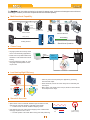
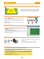
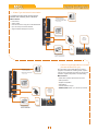
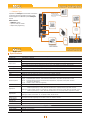
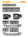
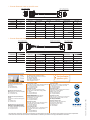
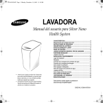
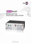
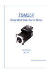
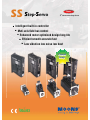
SS Ƶ Step-Servo New 3rd Generation Step-Servo Intelligent built-in controller Ƶ Muti-axis ł AH@>QOcontrol Ƶ "JD=J?A@IKPKNKLPEIEVA@@AOECJHKJCHEBA Ƶ "Bł ?EAJPOIKKPD=??QN=PAB=OP Ƶ Low vibration low noise low heat Closed Loop 9 Compliant Feature The is an innovative revolution for the world of stepper motor, it enhances the stepper motors with servo technology to create a product with exceptional feature and broad capability. Multi-functional Capability UP TO RS-485 UP TO 32 AXES 127 AXES Pulse&Dir CW/CCW A/B Quadrature 3rd Party Controller IDn Pulse Control ID2 ID1 Muti-Axis Network 5V Analog Velocity Analog Position Downloading Ain Analog Control Motion Program 0 Stand Alone Operation Closed Loop Very tight position and velocity control for the most demanding applications. Motion Command Robust servo loops that tolerate wide fluctuation in load inertia and frictional loading. Servo Controller P Veloc it y Closed Loop Motor Shaft Encoder ition os Precise positioning to within ±1 count using high resolution(20000 counts/ rev) encoder. Amplifier Torq ue Feedback /RZ+HDWLQJ+LJK(I¿FLHQF\ Uses only the current required by the application, generating minimum heat output. When stand-still, current can reach nearly zero for extremely low heat output. Heat Loss energy Power Output 30% Heat Loss Stepper energy Power Output 80% Being able to use almost 100% of torque, allows for more efficient and compact motor usage. SS Smooth & Accurate Space vector current control with 5000 line high resolution encoder, gives smooth and quiet operation, especially at low speeds. ------A feature never found with traditional stepping motors High stiffness due to the nature of the stepping motor combined with the highly responsive servo control ------Accurate position control both while running and static positioning 2 Stepper SS ±1 Count Error (20000 counts/rev) Feature Fast Response Servo Distance Step Typical Application for Step Servo When performing fast point-to-point moves, the high torque output and advanced servo control provides a very responsive system far exceeding what can be done with a conventional stepper system. Velocity High Torque operates in full servo mode, all the available Because the torque of the motor can be used. 150% The motor can provide as much as 50% more torque in many applications. High torque capability often eliminates the need for gear reduction. Boost torque capability can provide as much as 50% more torque for short, quick moves. Stepper Motion Monitoring 100% 70% Rated Torque Boost Continuous SS For dif¿cult control situations where performing a precise move is necessary, the Quick Tuner provide an easy to use interface for performing and monitoring the motion pro¿le. Many common parameters such as Actual Speed or Position Error can be monitored to evaluate system performance. The monitoring is interactive with the servo tuning capability so that optimum performance can be achieved. Easy Tuning 1:10 1:5 1:1 Pre-de¿ned tuning parameters for maximum control performance and stability. Easy selection list provides the level of control desired. Load Inertia In most cases NO extra manual tuning is required. Key Features Up to 8 digital inputs, 4 digital outputs and 2 analog inputs for S/Q/C type A/B/Z differential encoder signal output supported for P/R type Automatic load inertia detection On board daisy chain connection for field bus control(RS-485, Modbus/RTU, CANopen) Multiple homing methods for S/Q type Software limit for S/Q type Built-in position table up to 63 points for S type 3 Software Step-Servo Quick Tuner Feature Q Programmer Friendly Interface Easy setup within just three steps Drive setup and configuration Servo Tuning and Sampling Motion testing and monitoring Write and save SCL command scripts Online help integrated Feature Single-axis motion control Stored program execution Multi-tasking Conditional processing Math functions Data registers Motion Profile simulation Online help integrated RS485 Bus Utility Feature Stream SCL commands from the command line Simple interface with powerful capability Easy setup with RS-485 for 32 axis network motion control Monitoring Status of I/O, drive, alarm and the other nine most useful motion parameters Write and save SCL command scripts Online help integrated Supports all RS-485 drives CANopen Test Tool Feature Friendly User Interface Multiple operation Mode Support Multi-Thread, High Performance CAN bus monitor and log function Kvaser/PEAK adapter support FREE DOWNLOAD Our software and user manual can be downloaded from our website: www.moonsindustries.com All software applications run on Windows 7, Vista, XP, NT, 2000, 32-bit or 64-bit 4 System Con¿guration ƺ -R Switch Setting Pulse Input Type Controlled via pulse generator. Main Features Accepts three types of pulse signal input as Pulse&Direction, CW/CCW and A/B Quadrature Encoder signal output, A/B/Z differential Con¿gutaion and Tuning via switches PLC Motion control card Pulse generator AC Source DC Power Supply Ordering Information 150W P/N: MF150A24AG-V 320W P/N: MF320A48AG-V ƺ -P Software Setting Pulse Input Type Controlled via pulse generator. USB-RS232 Converter P/N: MS-USB-RS232-01 RS232 Communication Cable P/N:2101-150 Main Features PC/Configuration PLC Motion control card Pulse generator AC Source DC Power Supply Ordering Information 150W P/N: MF150A24AG-V 320W P/N: MF320A48AG-V 5 Accepts three types of pulse signal input as Pulse&Direction, CW/CCW and A/B Quadrature Encoder signal output, A/B/Z differential System Con¿guration ƺ -S Basic Type with Serial Communication Controlled via pulse signals, analog signal or MOONS' SCL streaming series commands. Main Features USB-RS232 Converter P/N: MS-USB-RS232-01 PC/Configuration RS232 Communication Cable P/N: 2101-150 Pulse control Analog control Host real time control using SCL via RS-232/RS-485 Up to 32 axes per channel for RS-485 Support Position Table(up to 63 points) PLC Motion control card Pulse generator RS485 Daisy Chain Connection AC Source DC Power Supply Ordering Information 150W P/N: MF150A24AG-V 320W P/N: MF320A48AG-V ƺ -Q Built-in Programmable Motion Controller (Includes Modbus/RTU type) USB-RS232 Converter P/N: MS-USB-RS232-01 Run stand-alone with sophisticated and functional programs. Commands for controlling motion, inputs & outputs, drive configuration and status, as well as math operations, register manipulation, and multi-tasking. PC/Configuration RS232 Communication Cable P/N: 2101-150 Main Features Stand-alone operation plus Serial host control Math operations Register manipulation Multi-tasking With all features in S type Modbus/RTU network, up to 32 axes per channel PLC Motion control card Pulse generator RS485 or Modbus/RTU Daisy Chain Connection AC Source DC Power Supply Ordering Information 150W P/N: MF150A24AG-V 320W P/N: MF320A48AG-V 6 System Con¿guration ƺ -CANopen Type USB-RS232 Converter P/N: MS-USB-RS232-01 Operates on a CANopen communication network and conforms to CiA301 and CiA402. It supports runing stored Q programs via MOONS'-specific CANopen objects. RS232 Communication Cable P/N: 2101-150 PC/Configuration Main Features CANopen Master CANopen network Up to 127 axes per channel Objects for Q programming PLC,Sensor,I/O CANopen Daisy Chain Connection AC Source DC Power Supply Ordering Information 150W P/N: MF150A24AG-V 320W P/N: MF320A48AG-V 6SHFLÀFDWLRQV Specifications Power Amplifier Amplifier Type Dual H-Bridge, 4 Quadrant Current Control 4 state PWM at 20 KHz SS03: Continuous Current 3A max, Boost Current 4.5A max (1.5s), current limitation auto set-up by attached motor Output Current SS05: Continuous Current 5A max, Boost Current 7.5A max (1.5s), current limitation auto set-up by attached motor SS10: Continuous Current 10A max, Boost Current 15A max (1.5s), current limitation auto set-up by attached motor Power Supply External nominal 24 - 75 volt DC power supply required, Absolute maximum input voltage range 18 - 80 VDC Protection Over-voltage, under-voltage, over-temp, motor/winding shorts (phase-to-phase, phase-to-ground) Electronic Gearing Software selectable from 200 to 51200 steps/rev in increments of 2 steps/rev Controller Filters Digital input noise filter, Analog input noise filter, Smoothing filter, PID filter, Notch filter Non-Volatile Storage Configurations are saved in FLASH memory on-board the DSP Modes of Operation R/P type: Position Mode(Pulse & Direction, CW & CCW Pulse, A/B Quadrature) S type: Position Mode(Pulse & Direction, CW & CCW Pulse, A/B Quadrature); Torque Mode, Velocity Mode, SCL Mode Q type: Position Mode(Pulse & Direction, CW & CCW Pulse, A/B Quadrature); Torque Mode, Velocity Mode, SCL Mode, Q Programming, Modbus/RTU C type: CANopen, CiA301, CiA402, Q Programming Position Table(S type only) Built-in Position Table, up to 63 positions Digital Inputs R/P type: X1/STEP, X2/DIR, X3/CW Limit, X4/CCW Limit; Optically isolated, differential, 5-24VDC; Minimum pulse width = 250 ns, Maximum pulse frequency = 2 MHz; X5/Enable, X6/Alarm ResetOptically isolated, single-ended, 5-24VDC S/Q/C type: X1/STEP, X2/DIR, X3/CW Limit, X4/CCW Limit; Optically isolated, differential, 5-24VDC; Minimum pulse width = 250 ns, Maximum pulse frequency = 2 MHz; X5/Enable, X6/Alarm Reset, X7, X8; Optically isolated, single-ended, 5-24VDC Digital Outputs R/P type: Y1/Alarm, Y2/In Position; Optically isolated, 30V/100 mA max S/Q/C type: Y1/Alarm, Y2/In Position, Y3, Y4; Optically isolated, 30V/100 mA max Analog Inputs (S/Q/C type only) Encoder Outputs (R/P type only) Two analog inputs Each input can accept a signal range of 0 to 5 VDC, ±5 VDC, 0 to 10 VDC or ±10 VDC +5V Output 4.8~5V, 100 mA max Communication RS-232, RS-485(optional), Modbus/RTU(optional), CANopen(optional) Ambient Temperature 0 to 40°C (32 to 104°F) when mounted to a suitable heatsink Ambient Humdity 90% Max., non-condensing Mass Approx 0.3 Kg Differential encoder outputs (A±, B±, Z±), 26C31 line driver, 20 mA sink or source max Physical 7 6SHFLÀFDWLRQV Dimensions(Unit:mm) Visit www.moonsindustries.com to get the 3D drawings. ƺ Motor 16.2 4-M2.5 Depth 2.5 Min AM24SS 60 B 23 0.1 28Max. AM11SS B1 47.14 4-¶4.5 36 L ( Max.) A 1 FLAT $ 4 7.14 23±0.1 2±0.2 1.5 AM17SS 7 7.4 L 43.8 52.9 64.1 33 0 ¶5-0.012 4.5±0.1 Model 300 15±0.5 10±0.2 0 ¶22-0.052 AM11SS1DMA AM11SS2DMA AM11SS3DMA ¶38.1 8 110 B B1 42.3 31 4-M3 Depth 4.5Min A A1 B B1 ´10 ´8 9.5 7.5 24 20 20 15 A 1 FLAT 31 4 2.3 A Model AM24SS3DGA AM24SS3DGB ¶22 L 2 33 86 37 AM34SS 300 25 69.6 6 9.6 1 3 FLAT 64 ¶14 4-6.5 10 A A1 B B1 L AM17SS1DGA AM17SS1DGB AM17SS2DGA AM17SS2DGB AM17SS3DGA AM17SS3DGB AM17SS4DGA AM17SS4DGB ´6 ´5 ´6 ´5 ´6 ´5 ´6 ´5 5.5 4.5 5.5 4.5 5.5 4.5 5.5 4.5 20 24 20 24 20 24 20 24 15 15 15 15 15 15 15 15 59.5 59.5 65 65 73.5 73.5 89 89 56.3 47.14 ¶73.025 2 300 38 4-¶5.1 Model L AM34SS1DGA AM34SS3DGA AM34SS5DGA 88 117.5 147 A 1 FLAT A 4 7.14 1 3 FLAT B B1 AM23SS L 1 02.7 Model ¶38.1 7 L 1.6 300 7 3.6 33 Model A A1 B B1 L AM23SS2DGA AM23SS2DGB AM23SS3DGA AM23SS3DGB ´8 ´6.35 ´8 ´6.35 7.5 5.85 7.5 5.85 24 20 24 20 20 15 20 15 77.5 77.5 99.5 99.5 ƺ Drive Ø4 39 .5 4 Ø4 30 39 .5 4 30 Ø4 39 .5 4 30 4 SW1 38400 OFF 57600 OFF OFF ON 115200 ON OFF ON Null OFF ON ON Null ON ON ON Null TERMINATING RESISTOR U V W 1 4 3 6 5 SW4 OFF ON Disconnected Connected Optional CANopen Board 8 10 12 7 9 11 14 13 16 15 SW1 A+ B+ Z+ SW2 SW3 OFF OFF OFF 1M ON OFF OFF 800K ON OFF ON OFF OFF +5V ON ON 500K 250K OFF OFF V+ ON OFF ON OFF ON ON 20K ON ON ON 12.5K 125K 50K TERMINATING RESISTOR Board. MA MA+ 3 1 4 2 SW4 MB MB+ OFF ON 2 1 2 A 4 B 6 Z GND U V W MA MA+ V+ 1 2 3 4 5 6 7 8 9 10 11 12 13 X1/STEP+ X1/STEP X2/DIR+ X2/DIR X3/CWLMT+ X3/CWLMT X4/CCWLMT+ X4/CCWLMT X5/EN X6/AR X7 X8 XCOM 14 15 16 17 18 19 20 21 22 23 24 25 26 AIN1 AIN2 GND Y1/ALM+ Y1/ALM Y2/INP+ Y2/INP Y3+ Y3 Y4+ Y4 +5V GND 8 10 12 1 3 5 7 9 11 14 13 16 15 3 1 4 2 SW1 PID 0 0 1 1 2 2 3 3 4 4 5 5 6 6 7 7 8 8 9 9 A A B B C C D D E E F F A+ B+ Z+ +5V U+ V+ W+ 2 1 SW1 SS Serial No. 1 SW2 EGearing SW3 PErr 0 200 0 0 1 400 1 1 2 500 2 2 3 800 3 3 4 1000 4 4 5 1600 5 5 6 2000 6 6 7 3200 7 7 8 3600 8 8 9 4000 9 9 A 5000 A A B 6400 B B C 7200 C C D 8000 D D E 10000 E E F 20000 F F Refer to Manual for Details. Available on Optional Switch MB MB+ RoHS Made in China V Pulse Mode Pulse & Dir CW & CCW Default Dir CW CCW Drive Setting by Software by Switches Reserved Rotary Switch Setting Disconnected Connected RoHS Made in China ID bps W+ U+ SW4 X1/STEP+ 2 X1/STEP 3 X2/DIR+ 4 X2/DIR 5 X3/CWLMT+ 6 X3/CWLMT 7 X4/CCWLMT+ 8 X4/CCWLMT - 9 X5/EN 10 X6/AR 11 ZOUT+ 12 ZOUT 13 XCOM 2 A 4 B 6 Z GND U V W Board. MA MA+ 8 10 14 NC 15 NC 16 NC 17 Y1/ALM+ 18 Y1/ALM 19 Y2/INP+ 20 Y2/INP 21 AOUT+ 22 AOUT 23 BOUT+ 24 BOUT 25 +5V 26 126 Z GND 2 SW3 SS Serial No. SW2 19200 OFF ON OPT 9600 OFF ON BAUD RATE A B SW4-1 OFF ON SW4-2 OFF ON SW4-3 OFF ON SW4-4 SW2 bps OFF OFF ON OPT SW3 OFF ON OFF 135 GND SW2 OFF DIP Switch Setting SW1 BAUD RATE SW1 126 RoHS Optional RS485 Board 135 Refer to Manual for Details. Available on Optional Switch 14 NC 15 NC 16 NC 17 Y1/ALM+ 18 Y1/ALM 19 Y2/INP+ 20 Y2/INP 21 AOUT+ 22 AOUT 23 BOUT+ 24 BOUT 25 +5V 26 126 135 SW2 EGearing SW3 PErr 0 200 0 0 1 400 1 1 2 500 2 2 3 800 3 3 4 1000 4 4 5 1600 5 5 6 2000 6 6 7 3200 7 7 8 3600 8 8 9 4000 9 9 A 5000 A A B 6400 B B C 7200 C C D 8000 D D E 10000 E E F 20000 F F X1/STEP+ 2 X1/STEP 3 X2/DIR+ 4 X2/DIR 5 X3/CWLMT+ 6 X3/CWLMT 7 X4/CCWLMT+ 8 X4/CCWLMT - 9 X5/EN 10 X6/AR 11 ZOUT+ 12 ZOUT 13 XCOM SW3 1 Rotary Switch Setting SW1 PID 0 0 1 1 2 2 3 3 4 4 5 5 6 6 7 7 8 8 9 9 A A B B C C D D E E F F SW2 SS Serial No. OPT Pulse Mode Pulse & Dir CW & CCW Default Dir CW CCW Drive Setting by Software by Switches Reserved SW3 SW4-1 OFF ON SW4-2 OFF ON SW4-3 OFF ON SW4-4 4 4 DIP Switch Setting GND 1 3 5 7 9 12 11 14 13 16 15 3 1 4 2 2 1 A+ B+ Z+ +5V U+ V+ W+ MB MB+ Made in China V+ V V+ 4.5 94.5 V 4.5 4.5 Model Model Model SS03-P-A SS05-P-A SS10-P-A SS03-S-A SS05-S-A SS10-S-A SS03-Q-A SS05-Q-A SS10-Q-A SS03-S-R SS05-S-R SS10-S-R SS03-Q-R SS05-Q-R SS10-Q-R SS03-C-C SS05-C-C SS10-C-C SS03-R-A SS05-R-A SS10-R-A 94.5 94.5 8 6SHFLÀFDWLRQV Motor Specifications Holding Torque Drive P/N AM11SS1DMA SS03-Ƶ-ƺ AM11SS2DMA AM11SS3DMA AM17SS1DG ƶ AM17SS2DG ƶ SS03-Ƶ-ƺor AM17SS3DG ƶ SS05-Ƶ-ƺ AM17SS4DG ƶ AM23SS2DG ƶ Frame Rotor Encoder Maximum Mass Size Inertia Resolution Speed 2 Nm gcm 0.05 9 0.07 12 0.09 18 218 0.3 38 390 0.5 57 440 0.6 82 0.75 123 0.9 260 460 AM24SS3DG ƶ 2.5 AM34SS1DGA 3.5 SS10-Ƶ-ƺ AM34SS3DGA AM34SS5DGA RPM g Distance(L) from Shaft End(mm) 0 5 10 15 20 28mm 20 2 5 34 52 - 42mm 35 44 58 85 - Permissible Thrust Load 118 1.5 SS05-Ƶ-ƺ AM23SS3DG ƶ counts/rev Permissible Overhung LoadNὈ 168 4096 Overhung Load Motor P/N Thrust Load 520 Less than the motor mass 760 3600 850 20000 56mm 63 75 95 130 190 900 1650 60mm 90 100 130 180 270 915 2000 6.0 1480 3100 80mm 260 290 340 390 480 8.0 2200 4200 1250 L ƶ˖A or B, refer to motor part numbering system; Ƶ˖R, P, S, Q, or C, refer to driver part numbering system; ƺ˖A, R or C, refer to driver part numbering system ƺ Torque Curves AM11SS Series AM11SS1DMA Continuous Boost 24V 24V AM11SS2DMA Continuous Boost 24V 24V AM11SS3DMA 80 80 120 60 40 20 Torque(mN·m) 150 Torque(mN·m) 100 Torque(mN·m) 100 60 40 10 20 30 40 90 60 0 0 0 24V 24V 30 20 0 Continuous Boost 50 0 Speed(rps) 10 20 30 40 0 50 10 20 30 Speed(rps) 40 50 Speed(rps) AM17SS Series Continuous 24V 48V Boost 24V 48V AM17SS2DGƑ Continuous 24V 48V Boost 24V 48V AM17SS3DGƑ 10 20 30 40 0.8 0.4 0.3 0.2 0.5 0.4 0.3 0.2 0.1 0.1 0 0 50 0 10 20 30 40 Continuous 24V 48V 70V Boost 24V 48V 70V 0 10 20 30 40 50 AM23SS3DGƑ Continuous 24V 48V 70V Boost 24V 48V 70V 1.2 AM24SS3DGƑ 24V 48V 70V Boost 24V 48V 70V 3 Torque(N·m) Torque(N·m) 0.6 Continuous 3.5 2 0.9 1.5 1 2.5 2 1.5 1 0.3 0.5 0 0 0 10 20 30 40 50 0.5 0 0 10 20 30 40 0 50 10 20 30 Speed(rps) Speed(rps) 40 50 Speed(rps) AM34SS Series AM34SS1DGA Continuous 24V 48V 70V Boost 24V 48V 70V AM34SS3DGA Continuous 24V 48V 70V Boost 24V 48V 70V AM34SS5DGA 6.0 2.0 24V 48V 70V Boost 24V 48V 70V 8.0 5.0 Torque(N·m) Torque(N·m) Torque(N·m) 3.0 Continuous 10 7.0 4.0 4.0 3.0 6.0 4.0 2.0 1.0 2.0 1.0 0 0 0 10 20 30 Speed(rps) 40 50 0 0 10 20 30 40 50 0 10 20 30 Speed(rps) Speed(rps) 9 48V 24V 48V 0.6 0.4 0 10 20 30 Speed(rps) Speed(rps) 2.5 24V Boost 0 50 AM24SS Series 1.5 Continuous 0.2 Speed(rps) AM23SS Series Torque(N·m) AM17SS4DGƑ 0.6 Speed(rps) AM23SS2DGƑ 48V 0.5 Torque(N·m) Torque(N·m) Torque(N·m) 0 48V 24V 1.0 0.1 0 24V Boost 0.7 0.3 0.2 Continuous 0.6 Torque(N·m) AM17SS1DGƑ 0.4 40 50 40 50 Ordering Information Numbering System AM11 SS 1 D G A Frame Size 11,17,23,24,34 Step Servo Motor Size 1 = 1Stack 2 = 2Stack 3 = 3Stack D=DC Input 4 = 4Stack 5 = 5Stack SS 03 P - A Mechanical Option A=Output shaft size 11:¶5 17:¶6 23:¶8 24:¶10 34:¶14 B=Output shaft size 17:¶5 23:¶6.35 24:¶8 Encoder G=5000-Line M=1024-Line Step Servo Output Current 03-3A 05-5A 10-10A A=RS-232 R=RS-485 C=CANopen R=Switch Setting Type P=Pulse Input Type S=Basic Type Q=Q Type(Modbus/RTU Type) C=CANopen Type Ordering Information Control Drive Type SS03-R-A R Type Pulse Input Type Selectable Switch & RS232 Software 6 Digital Inputs 2 Digital Outputs Encoder Output SS03-R-A / SS05-R-A SS05-R-A SS10-R-A Control Drive Type SS03-S-A S Type Basic Type RS232 Communication 8 Digital Inputs 4 Digital Outputs 2 Analog Inputs SS03-S-A / SS05-S-A SS05-S-A SS10-S-A Control Drive Type SS03-Q-A Q Type Programm Type RS232 Communication SS03-Q-A / SS05-Q-A Modbus/RTU 8 Digital Inputs 4 Digital Outputs 2 Analog Inputs SS05-Q-A SS10-Q-A Control Drive Type SS03-C-C C Type CANopen 8 Digital Inputs 4 Digital Outputs 2 Analog Inputs SS03-C-C / SS05-C-C SS05-C-C SS10-C-C Motor Type AM11SS1DMA AM11SS2DMA AM11SS3DMA AM17SS1DG ƶ AM17SS2DG ƶ AM17SS3DG ƶ AM17SS4DG ƶ AM23SS2DG ƶ AM23SS3DG ƶ AM24SS3DG ƶ AM34SS1DGA AM34SS3DGA AM34SS5DGA Torque 0.05N·m 0.07N·m 0.09N·m 0.3N·m 0.5N·m 0.6N·m 0.75N·m 0.9N·m 1.5N·m 2.5N·m 3.5N·m 6.0N·m 8.0N·m Motor Type AM11SS1DMA AM11SS2DMA AM11SS3DMA AM17SS1DG ƶ AM17SS2DG ƶ AM17SS3DG ƶ AM17SS4DG ƶ AM23SS2DG ƶ AM23SS3DG ƶ AM24SS3DG ƶ AM34SS1DGA AM34SS3DGA AM34SS5DGA Torque 0.05N·m 0.07N·m 0.09N·m 0.3N·m 0.5N·m 0.6N·m 0.75N·m 0.9N·m 1.5N·m 2.5N·m 3.5N·m 6.0N·m 8.0N·m Motor Type AM11SS1DMA AM11SS2DMA AM11SS3DMA AM17SS1DG ƶ AM17SS2DG ƶ AM17SS3DG ƶ AM17SS4DG ƶ AM23SS2DG ƶ AM23SS3DG ƶ AM24SS3DG ƶ AM34SS1DGA AM34SS3DGA AM34SS5DGA 0.05N·m 0.07N·m 0.09N·m 0.3N·m 0.5N·m 0.6N·m 0.75N·m 0.9N·m 1.5N·m 2.5N·m 3.5N·m 6.0N·m 8.0N·m Motor Type AM11SS1DMA AM11SS2DMA AM11SS3DMA AM17SS1DG ƶ AM17SS2DG ƶ AM17SS3DG ƶ AM17SS4DG ƶ AM23SS2DG ƶ AM23SS3DG ƶ AM24SS3DG ƶ AM34SS1DGA AM34SS3DGA AM34SS5DGA 0.05N·m 0.07N·m 0.09N·m 0.3N·m 0.5N·m 0.6N·m 0.75N·m 0.9N·m 1.5N·m 2.5N·m 3.5N·m 6.0N·m 8.0N·m Torque Control Drive Type SS03-P-A P Type Pulse Input Type RS232 Software 6 Digital Inputs 2 Digital Outputs Encoder Output SS03-P-A / SS05-P-A SS05-P-A SS10-P-A Control Drive Type SS03-S-R S Type Basic Type RS485 Communication 8 Digital Inputs 4 Digital Outputs 2 Analog Inputs SS03-S-R / SS05-S-R SS05-S-R SS10-S-R Control Drive Type SS03-Q-R Q Type Programm Type RS485 Communication SS03-Q-R / SS05-Q-R Modbus/RTU 8 Digital Inputs 4 Digital Outputs 2 Analog Inputs SS05-Q-R SS10-Q-R Torque ƶ : Enter A(Enhanced Shaft) or B(Standard) in the box( ƶ ) within the model name 10 Motor Type AM11SS1DMA AM11SS2DMA AM11SS3DMA AM17SS1DG ƶ AM17SS2DG ƶ AM17SS3DG ƶ AM17SS4DG ƶ AM23SS2DG ƶ AM23SS3DG ƶ AM24SS3DG ƶ AM34SS1DGA AM34SS3DGA AM34SS5DGA Torque 0.05N·m 0.07N·m 0.09N·m 0.3N·m 0.5N·m 0.6N·m 0.75N·m 0.9N·m 1.5N·m 2.5N·m 3.5N·m 6.0N·m 8.0N·m Motor Type AM11SS1DMA AM11SS2DMA AM11SS3DMA AM17SS1DG ƶ AM17SS2DG ƶ AM17SS3DG ƶ AM17SS4DG ƶ AM23SS2DG ƶ AM23SS3DG ƶ AM24SS3DG ƶ AM34SS1DGA AM34SS3DGA AM34SS5DGA Torque 0.05N·m 0.07N·m 0.09N·m 0.3N·m 0.5N·m 0.6N·m 0.75N·m 0.9N·m 1.5N·m 2.5N·m 3.5N·m 6.0N·m 8.0N·m Motor Type AM11SS1DMA AM11SS2DMA AM11SS3DMA AM17SS1DG ƶ AM17SS2DG ƶ AM17SS3DG ƶ AM17SS4DG ƶ AM23SS2DG ƶ AM23SS3DG ƶ AM24SS3DG ƶ AM34SS1DGA AM34SS3DGA AM34SS5DGA 0.05N·m 0.07N·m 0.09N·m 0.3N·m 0.5N·m 0.6N·m 0.75N·m 0.9N·m 1.5N·m 2.5N·m 3.5N·m 6.0N·m 8.0N·m Torque Accessories Standard Accessories P/N Catagory Technical Specification 1103-200 Cable Power Supply Cable 2101-150 Cable RS232 Communication Cable Optional Accessories (Sold separately) P/N Catagory Technical Specification MF150A24AG-V Switching Power Supply 150W, 24V MF320A48AG-V Switching Power Supply 320W, 48V 2103-ƶƶƶ Cable Motor Extension Cable for AM17/23/24/34SS motor 2109-ƶƶƶ Cable Motor Extension Cable for AM11SS motor 2104-ƶƶƶ Cable Encoder Extension Cable for AM17/23/24/34SS motor 2108-ƶƶƶ Cable Encoder Extension Cable for AM11SS motor ƺ Switching Power Supplies MOONS' recommend to use following switching power supplies P/N:MF150A24AG-V 150W,24VDC 5 9 18 2 1 49.5 8 4-M4 L=4mm 3 4-M4 L=4mm 2 4 3 63 63 5 Air flow direction 9.5 99 4 9.5 1 18 8 11.5MAX 199 157 18 11.5MAX 45 5 99 170 152 65 P/N:MF320A48AG-V 320W,48VDC 6 FAN 7 6 V ADJ. 7 4MAX V ADJ. LED CN3 2 1 LED 4-M4 L=4mm 5 CN3 4 8 1 117 12.5 52 25 12.5 12.5 25 44 25 3-M4 L=4mm 28 25 130 ƺ Motor Extended Cable for AM11SS motor P/N Length 2109-100 1M PINJ1Ὀ 2109-300 3M 1 BlueB-Ὀ 1 2109-500 5M 3 RedB+Ὀ 2 2109-1000 10M 4 GreenA-Ὀ 3 6 BlackA+Ὀ 4 Wiring Diagram Colour(Signal) PINJ2Ὀ Housing:39-01-3048(Molex) Crimp: 39-00-0038(Molex) Housing:51065-0600(Molex) Crimp: 50212-8000(Molex) 6 J1 2 4 1 3 J2 1 L ƺ Motor Extended Cable for AM17/23/24/34SS motor P/N Length 2103-100 1M PINJ1Ὀ 2103-300 3M 1 BlueB-Ὀ 1 2103-500 5M 2 RedB+Ὀ 2 2103-1000 10M 3 GreenA-Ὀ 3 4 BlackA+Ὀ 4 Wiring Diagram Colour(Signal) Housing:39-01-3049(Molex) Crimp:39-00-0040(Molex) PINJ2Ὀ Housing:39-01-3048(Molex) Crimp:39-00-0038(Molex) J1 4 2 2 4 3 1 1 3 L 11 J2 ƺ Encoder Extended Cable for AM11SS motor Housing:501646-1200(Molex) Crimp: 501648-1000(Molex) 2 Housing:J21DF-16V-KX-L(JST) Crimp: SJ2F-002GF-P1.0(JST) A B 1 1 1 J1 J2 12 8 11 8 L P/N Length 2108-100 1M PINJ1Ὀ Wiring Diagram Colour(Signal) PINJ2Ὀ 2108-300 3M 10 BlueA+Ὀ A8 BrownU+Ὀ A3 2108-500 5M 9 Blue/BlackA-Ὀ B8 Brown/BlackU-Ὀ B3 2108-1000 10M 8 GreenB+Ὀ A7 GrayV+Ὀ A2 7 Green/BlackB-Ὀ B7 Gray/BlackV-Ὀ B2 6 YellowZ+Ὀ A6 WhiteW+Ὀ A1 5 Yellow/BlackZ-Ὀ B6 2 White/BlackW-Ὀ B1 3 Red+5VὈ A5 12 Shield B4 4 BlackGNDὈ B5 Colour(Signal) PINJ2Ὀ PINJ1Ὀ 1 ƺ Encoder Extended Cable for AM17/23/24/34SS motor Housing:J21DPM-16V-KX(JST) Crimp:SJ2M-002GF-M1.0N(JST) B 1 Wire protect cover: J21PF-16SCA(JST) Wire protect cover: J21PF-16SCB(JST) Housing:J2DF-16V-KX-L(JST) Crimp:SJ2F-002GF-P1.0(JST) A B A 1 1 1 8 8 8 J2 J1 8 L P/N Length 2104-100 1M PINJ1Ὀ Wiring Diagram 2104-300 3M A8 2104-500 5M 2104-1000 10M Colour(Signal) PINJ2Ὀ PINJ1Ὀ Colour(Signal) BlueA+Ὀ A8 A3 BrownU+Ὀ A3 B8 Blue/BlackA-Ὀ B8 B3 Brown/BlackU-Ὀ B3 A7 GreenB+Ὀ A7 A2 GrayV+Ὀ A2 B7 Green/BlackB-Ὀ B7 B2 Gray/BlackV-Ὀ B2 A1 A6 YellowZ+Ὀ A6 A1 WhiteW+Ὀ B6 Yellow/BlackZ-Ὀ B6 B1 White/BlackW-Ὀ B1 A5 Red+5VὈ A5 B4 Shield B4 B5 BlackGNDὈ B5 Headquarters No. 168 Mingjia Road Industrial Park North Minhang District Shanghai 201107, P.R. China Tel: +86(0)21-5263 4688 Fax: +86(0)21-6296 8682 Web: www.moonsindustries.com E-mail: [email protected] Service Center 400-820-9661 MOONS' Industries (America), Inc. 1113 North Prospect Avenue,Itasca, IL 60143 U.S.A. Tel: 001-630-833-5940 Fax: 001-630-833-5946 6KHQ]KHQ%UDQFK2I¿FH Room 2209, 22/F, Kerry Center, 2008 Renminnan Road, Luohu District, Shenzhen 518001, P.R.China Tel: +86 (0)755 25472080 Fax: +86 (0)755 25472081 ;L¶DQ%UDQFK2I¿FH Room 1006, Tower D, Wangzuo International City, 1 Tangyan Road, Xiÿan 710065, P.R. China Tel: +86 (0)29 81870400 Fax: +86 (0)29 81870340 MOONS' Industries (Europe) S.r.l. Via Torri Bianche n.1 20059 Vimercate(MB) Italy Tel: +39 039 62 60 521 Fax: +39 039 96 31 409 %HLMLQJ%UDQFK2I¿FH Room 816, Tower B, China Electronics Plaza, 3 Danling Street, Haidian District, Beijing 100080, P.R. China Tel: +86 (0)10 58753312 Fax: +86 (0)10 58752279 1DQMLQJ%UDQFK2I¿FH Room 302, Building A, Tengfei Creation Center, 55 Jiangjun Road, Jiangning District, Nanjing 211100, P.R. China Tel: +86 (0)25 52785841 Fax: +86 (0)25 52785485 4LQJGDR%UDQFK2I¿FH Room E, 10th Floor, 73 Wangjiao Mansion, Hongkong Middle Road, Shinan District, Qingdao 266071, P.R. China Tel: +86 (0)532 85879625 Fax: +86 (0)532 85879512 1LQJER%UDQFK2I¿FH Room 309, Tower B, Taifu Plaza, 565 Jiangjia Road, Jiangdong District, Ningbo, 315040, P.R. China Tel: +86 (0) 574-87052739 Fax: +86 (0) 574-87052365 MOONS’ Industries Japan Corporation. Room 601, 6F, Shin Yokohama Koushin Building 2-12-1, Shin-Yokohama, Kohokuku, Yokohama, Kanagawa Japan 222-0033 Tel: +81-(0)45-475-5788 Fax: +81-(0)45-475-5787 :XKDQ%UDQFK2I¿FH Room 3001, World Trade Tower, 686 Jiefang Avenue, Jianghan District, Wuhan 430022, P.R.China Tel: +86 (0)27 85448742 Fax: +86 (0)27 85448355 ISO 9001 *XDQJ]KRX%UDQFK2I¿FH Room 4006, Tower B, China Shine Plaza, 9 Linhe Xi Road, Tianhe District, Guangzhou 510610, P.R. China Tel : 020-38010153 Fax: 020-38103661 ISO 14001 ISO/TS 16949 &KHQJGX%UDQFK2I¿FH Room 1917, Western Tower, 19, 4th Section of South People Road, Wuhou District, Chengdu 610041, P.R.China Tel: +86 (0)28 85268102 Fax: +86 (0)28 85268103 7KHPRGHOQDPHVVSHFL¿FDWLRQVDSSHDUDQFHVDQGRWKHUGHWDLOVRISURGXFWVIHDWXUHGLQWKLVEURFKXUHDUHVXEMHFWWRFKDQJHZLWKRXWQRWLFHIRUSXUSRVHVRILPSURYHPHQW 3OHDVHFKHFNZLWKRXUVDOHVRI¿FHWRFRQ¿UPWKDWWKHVWDWHGLQIRUPDWLRQLVYDOLGEHIRUH\RXH[DPLQHRURUGHUDQ\SURGXFWIHDWXUHGLQWKHEURFKXUH CHINA / 1ST PRINT / 03TH / JUNE / 2014 MOONS' Industries (South-East Asia) Pte Ltd. 33 Ubi Avenue 3 #08-23 Vertex Singapore 408868 Tel: +65 6634 1198 Fax: +65 6634 1138 PINJ2Ὀ