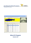
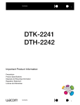
1
Control and Remote Control Software PSW 160 V.6 English for head-end stations of the Basic-Line GSS Grundig SAT Systems GmbH Beuthener Strasse 43 D-90471 Nuremberg Phone: Fax: Email: Internet: +49 (0) 911 / 703 8877 +49 (0) 911 / 703 9210 [email protected] www.gss.de Contents 1 Software License Agreement......................................................................... 4 1.0 Software License Agreement......................................................4 1.1 Definitions...............................................................................4 1.2 Software License.......................................................................4 1.3 Obligations and Restrictions.......................................................5 1.4 Transfer...................................................................................5 1.5 Intellectual Property Ownership, Reservation of Rights...................5 1.6 No Warranty...........................................................................5 1.7 Limitation of Liability..................................................................5 1.8 General Provisions....................................................................6 1.9 Compliance with Licenses..........................................................6 2 General information..................................................................................... 7 2.1 Distribution....................................................................................7 2.2 Meaning of the used symbols...........................................................7 2.3 Description....................................................................................7 2.4 At least needed software versions.....................................................8 2.5 PC system requirements...................................................................9 3 Installing the software on a PC.................................................................... 10 3.1 Key Code (Activation Code) for the software....................................10 3.2 Installing the software....................................................................10 4 Basic configuration of the plant................................................................... 14 4.1 In situ operation (Direct connection)................................................14 4.2 Remote control via a management system........................................14 5 Connection to the plant............................................................................... 15 5.1 Requirements/Hints.......................................................................15 5.2 Connection via COM port (in situ connection)..................................16 5.3 Connection via Ethernet.................................................................17 6 Controlling the plant................................................................................... 18 6.1 Main window – buttons.................................................................18 6.2 Read data (configuration)..............................................................19 6.3 Menu File – Administrate the configuration data...............................20 Create a new plant...................................................................20 Open plant.............................................................................21 Save plant..............................................................................21 - 2 - PSW 160 Save plant as….......................................................................22 Export overview file.................................................................22 Last used files..........................................................................23 Exit........................................................................................24 6.4 Menu plant..................................................................................25 Read data...............................................................................25 Send data...............................................................................26 Control unit.............................................................................27 Activate connection / Deactivate connection..........................28 Ethernet access data................................................................29 Ethernet password...................................................................29 NIT (Network Information Table)................................................30 Section "Selection of the transponder" > Tap Modul NIT:..............31 Section "Selection of the transponder" > Tap Plant Output:...........32 Section "Selection of the transponder" > Tap New Transponder:...33 Section "Selection of the transponder" > Tap Import:....................34 Section "Overview of the new NIT":..........................................36 Logical Channel Number - LCN.................................................38 Save the NIT in form of a "*.oni file" (LCN included):..................41 Complete the NIT processing....................................................42 Transfer the NIT to the station:..............................................42 Export NIT as *.nit file (without LCN):...................................42 Inport NIT (*.nit file without LCN):........................................43 Copy NIT (directly into the modules of the station - LCN included).. 43 6.5 Menu Help..................................................................................45 Operating instruction...............................................................45 Language....................................................................................45 Minimum requirements..................................................................46 Searching for updates..............................................................46 Info about …...............................................................................48 7 Final Hints.................................................................................................. 48 8 Index......................................................................................................... 49 - 3 - PSW 160 1 SOFTWARE LICENSE AGREEMENT 1 Software License Agreement This document includes warranty information and a license agreement governing the use of GSS Grundig SAT Systems GmbH software. 1.0 S o f t wa r e L i c e n s e A g r e e m e n t By using, copying or distributing the GSS software, you accept all the terms and conditions of this agreement, including, in particular, the provisions on: – Use contained in section 1.2; – Transferability in section 1.4; – Warranty in section 1.6 and liability in section 1.7. Upon acceptance, this agreement is enforceable against you and any entity that obtained the software and on whose behalf it is used. If you do not agree, do not use the software. GSS permits you to use the software only in accordance with the terms of this agreement. 1.1 D e f i n i t i o n s "GSS" means GSS Grundig SAT Systems, a limited company, Beuthener Str. 43, 90471 Nuremberg, Germany. "Computer" means a virtual or physical personal electronic device that accepts information in digital or similar form and manipulates it for a specific result based on a sequence of instructions. "Software" means all of the contents of the files (delivered electronically or on physical media), or CD or other media with which this agreement is provided, which may include GSS or third party computer information or software, including GSS "PSW 160"; related explanatory written materials or files ("Documentation"); and upgrades, modified versions, updates, additions, and copies of the foregoing, provided to you by GSS at any time (collectively, "Updates"). "Use" means to access, install, download, copy, or otherwise benefit from using the functionality of the Software. 1.2 S o f t wa r e L i c e n s e If you obtained the Software from GSS or one of its authorized licensees, and subject to your compliance with the terms of this agreement, including the restrictions in Section 1.3, GSS grants to you a non-exclusive license to use the Software in the manner and for the purposes described in the Documentation as follows: 1.2.1 General Use You may install and use one copy of the Software on your compatible Computer. See Section 1.3 for important restrictions on the use of the Software. 1.2.2 Server Use This agreement does not permit you to install or use the software on a computer file server. 1.2.3 Distribution This license does not grant you the right to sublicense or distribute the Software. 1.2.4 Backup Copy You may make one backup copy of the Software, provided your backup copy is not installed or used. You may not transfer the rights to a backup copy unless you transfer all rights in the Software as provided under Section 1.4. - 4 - PSW 160 1 SOFTWARE LICENSE AGREEMENT 1.3 O b l i gat i o n s 1.3.1 Notices Any copy of the Software that you make must contain the same copyright and other proprietary notices that appear on or in the Software. 1.3.2 No Modification or Reverse Engineering You may not modify, adapt, translate or create derivative works based upon the Software. You will not reverse engineer, decompile, disassemble or otherwise attempt to discover the source code of the Software except to the extent you may be expressly permitted to reverse engineer or decompile under applicable law. 1.4 T r a n s f e r You may not rent, lease, sublicense, assign or transfer your rights in the Software, or authorize all or any portion of the Software to be copied onto another user’s Computer except as may be expressly permitted by this agreement. You may, however, transfer all your rights to use the Software to another person or legal entity provided that: – you also transfer this agreement, and the Software and all other software or hardware bundled or pre-installed with the Software, including all copies, updates and prior versions, to such person or entity, – you retain no copies, including backups and copies stored on a Computer, and – the receiving party accepts the terms and conditions of this agreement and any other terms and conditions upon which you obtained a valid license to the Software. Notwithstanding the foregoing, you may not transfer education, pre-release, or not for resale copies of the Software. Restrictions 1.5 I n t e ll e c t ua l P r o p e r t y O w n e r s h i p, R e s e rvat i o n The Software and any authorized copies that you make are the intellectual property of GSS. The structure, organization and code of the Software are the valuable trade secrets and confidential information of GSS. Except as expressly stated herein, this agreement does not grant you any intellectual property rights in the Software and all rights not expressly granted are reserved by GSS. 1.6 N o Wa r r a n t y. The software is being delivered to you "as is" and with all faults. GSS and its suppliers do not and cannot warrant the performance or results you may obtain by using the software, certificate authority services or other third party offerings. Except to the extent any warranty, condition, representation or term cannot or may not be excluded or limited by law applicable to you in your jurisdiction, GSS and its suppliers make no warranties conditions, representations, or terms (express or implied whether by statute, common law, custom, usage or otherwise) as to any matter including without limitation noninfringement of third party rights, merchantability, integration, satisfactory quality, or fitness for any particular purpose. The provisions of section 1.6 and section 1.7 shall survive the termination of this agreement, howsoever caused, but this shall not imply or create any continued right to use the software after termination of this agreement. 1.7 L i m i tat i o n 1.7.1 In no event will GSS or its suppliers be liable to you for any damages, claims or costs whatsoever including any consequential, indirect, incidental damages, or any lost profits or lost savings, even if an GSS representative has been advised of the possibility of such loss, damages, or claims. The foregoing limitations and exclusions apply to the extent permitted by applicable law in your jurisdiction. GSS’ aggregate liability and that of its suppliers under or in connection with this agreement shall be limited to the amount paid for the software, if any. Nothing contained in this agreement limits GSS’ liability to you in the event of death or personal and of of Rights L i a b i l i t y. - 5 - PSW 160 1 SOFTWARE LICENSE AGREEMENT injury resulting from GSS’ negligence or for the tort of deceit (fraud). GSS is acting on behalf of its suppliers and Certificate Authorities for the purpose of disclaiming, excluding and/or limiting obligations, warranties and liability as provided in this agreement, but in no other respects and for no other purpose. 1.7.2 Limitation of Liability for Users Residing in Germany and Austria 1.7.2.1 If you obtained the Software in Germany or Austria, and you usually reside in such country, then Section 1.7.1 does not apply, Instead, subject to the provisions in Section 1.7.2.2, GSS’ statutory liability for damages shall be limited as follows: – GSS shall be liable only up to the amount of damages as typically foreseeable at the time of entering into the license agreement in respect of damages caused by a slightly negligent breach of a material contractual obligation and – GSS shall not be liable for damages caused by a slightly negligent breach of a non-material contractual obligation. 1.7.2.2 The aforesaid limitation of liability shall not apply to any mandatory statutory liability, in particular, to liability under the German Product Liability Act, liability for assuming a specific guarantee or liability for culpably caused personal injuries. 1.7.2.3 You are required to take all reasonable measures to avoid and reduce damages, in particular to make back-up copies of the Software and your computer data subject to the provisions of this agreement. 1.8 G e n e r a l P r ov i s i o n s . If any part of this agreement is found void and unenforceable, it will not affect the validity of the balance of this agreement, which shall remain valid and enforceable according to its terms. This agreement shall not prejudice the statutory rights of any party dealing as a consumer. This agreement may only be modified by a writing signed by an authorized officer of GSS. Updates may be licensed to you by GSS with additional or different terms. This is the entire agreement between GSS and you relating to the Software and it supersedes any prior representations, discussions, undertakings, communications or advertising relating to the Software. 1.9 C o m pl i a n c e If you are a business or organization, you agree that upon request from GSS or GSS’ authorized representative, you will, within thirty (30) days, fully document and certify that use of any and all Software at the time of the request is in conformity with your valid licenses from GSS. with Licenses. - 6 - PSW 160 2 GENERAL INFORMATION 2 General information 2.1 D i s t r i b u t i o n The software can be downloaded from "www.gss.de". 2.2 M e a n i n g o f t h e u s e d s ym b o l s Important note —> General note • Performing works —> The shown illustrations of menus are partly dependent on the cassettes resp. its software versions as well as the used operating system and its settings. Variations are possible. 2.3 D e s c r i p t i o n The PSW 160 allows to configure, record and store the settings of head-end stations / plants of the basic line. —> All settings (with exception of the "direct control via the virtual control unit") first will be done in the PSW 160 software (random access memory – RAM of PC) and must be finally transferred to the plant ("send data")! All current modules and the head-end station of the basic line can be controlled with a PC directly (local) via the serial COM port interface of the head-end station, or remote controlled via the Ethernet by using a corresponding management system. Without management system always one head-end station can be configured. For a local configuration of the head-end station connect the PC to the control unit via a RS-232 cable. For PCs with USB connector (without serial interface) we recommend the DeLOCK "USB 2.0 to serial adapter" (product-No. 61460). —> Using an UMTS router, also a connection PC Ethernet telephony Management system is possible. - 7 - Mobile PSW 160 2 GENERAL INFORMATION Software updates: Always keep the software versions of the head-end stations and the PSW 160 up-to-date in order to be able to configure also the newest products. (see page 8 for the software versions needed at least). —> The most recent version can be downloaded from "www.gss.de". If you do not have Internet access, we will send you a DVD on request. 2.4 A t l e a s t n e e d e d s o f t wa r e v e rs i o n s A current table of supported modules and their software versions needed at least is shown during the installation in window "information" (page 11) and can also be called up via menu Help > Minimum requirements. —> Versions numbers in squared brackets e.g. [V 10] indicate that the software of the module is included in the software of the control unit. - 8 - PSW 160 2 GENERAL INFORMATION 2.5 PC s ys t e m r e q u i r e m e n t s System requirements for the PSW 160 software: – Microsoft .NET Framework 3.5 (can be downloaded from Microsoft free of charge). —> During installation of PSW160 it is checked whether .NET F 3.5 is installed. If not, the download from Microsoft will be provided. If Microsoft .NET Framework 3.5 is not installed, it is not possible to install the PSW160 software! – Supported Operating Systems: Windows Server 2003, Windows Server 2008, Windows Vista, Windows XP, Windows 7. – Processor: 400 MHz Pentium processor or equivalent (minimum); 1GHz Pentium processor or equivalent (recommended). – RAM: 96 MB (minimum); 256 MB (recommended). – Hard Disk: Up to 500 MB of available space may be required. – Display: 800 x 600, 256 colours (minimum); 1024 x 768 high colour, 32bit (recommended). – LAN interface (RJ-45 socket, for remote control via Ethernet). – Serial interface (RS-232 Sub D, for in situ operation). —> For PCs with USB connector (without serial interface), we recommend the DeLOCK "USB 2.0 to Serial adapter" (Product No. 61460). – Network-/Internet access for downloads and for remote control via Ethernet. - 9 - PSW 160 3 INSTALLING THE SOFTWARE ON A PC 3 I n s t a ll i n g the software on a 3.1 K e y C o d e (A c t i vat i o n C o d e ) f o r t h e s o f t wa r e A key code is required for the activation of the PSW 160 software. This can be obtained from your regional authorised distributor. 3.2 I n s ta ll i n g PC t h e s o f t wa r e The PSW 160 software can be downloaded from "www.gss.de". If you do not have Internet access, we will send you a DVD on request. • Start the "SETUP_PSW160_v.X.exe" programme by a double click. • Select the desired language and click the OK button to confirm. • When the "Setup-PSW160" menu appears, click the "Next >" button. - 10 - PSW 160 3 INSTALLING THE SOFTWARE ON A PC • Read the license agreement. • If you accept the license agreement select "I accept the agreement" and click the "Next >" button. • The appearing table shows the software versions of the modules, from which on they can read out. —> Keep the software version of the PSW 160 always up-to-date in order to be able to remote control also the newest products. —> After installing the PSW 160 software, update the software for the cassettes if necessary. • Click the "Next >" button. - 11 - PSW 160 3 INSTALLING THE SOFTWARE ON A PC • Specify the directory in which the PSW 160 should be installed (e.g. C:\Program Files\GSS\PSW160) and click the "Next >" button. • Enter a name for the shortcut to the programme which will be created in the start menu and click the "Next >" button. • If you would like to have a "Quick Launch Icon" enter a hook at this check field (dependent on the operating system of the PC) and click the "Next >" button. - 12 - PSW 160 3 INSTALLING THE SOFTWARE ON A PC • Click on "Install" in order to proceed with the installation of the programme, or on "Back" to make corrections or changes. —> The installation progress is shown. • Click on "Finish", to complete the installation. - 13 - PSW 160 4 BASIC CONFIGURATION OF THE PLANT 4 Basic 4.1 I n c o n f i g u r a t i o n o f t h e pl a n t s i t u o p e r at i o n (D i r e c t connection) Via direct connection it is possible to control the head-end station more comfortable than via the control unit. In addition the configuration can be stored on the PC. 1 2 3 • Connect the RS-232 interface 1 on the control unit with the serial interface (e.g. COM 1) on the PC using a commercially available RS-232 cable 2. For PCs without a serial interface, we recommend the DeLOCK "USB 2.0 to Serial Adapter" (Product No. 61460). 3. 4.2R e m ot e c o n t r o l v i a a m a n ag e m e n t s ys t e m The basic configuration depends on the desired type of connection (Internet or local network). It must be done during the installation process of the management system and is therefore described in the assembly instruction of the management system. Remote PC RCA 162 RCU 160 RS 232 Internet LAN - 14 - Router/Switch PC local PSW 160 5 CONNECTION TO THE PLANT 5 Connection 5.1 R e q u i r e m e n t s/H i n t s The basic configuration of the used management system must already be done during its assembly. t o t h e pl a n t —> Therefore observe the assembly instruction of the management unit. • Start the PSW 160 software. —> A key code is required for the activation of the programme. This can be obtained from your regional authorised distributor. • Click the "OK" button when entered the 25 key code. —> The hyphen between the column of figures will be added from the software. —> Via menu "Help > Language" select the language of the menus. - 15 - PSW 160 5 CONNECTION TO THE PLANT 5.2 C o n n e c t i o n • Click the via COM port (in situ connection) button. —> The "Connection settings" window is activated. • Select tap "COM". —> The COM interfaces available in your PC system are displayed. —> Using button you can search for used COM ports. • Select the corresponding COM interface. —> Via the Windows system control you can check, which COM port is used for an USB RS-232 adapter. • Click the button. —> The virtual control unit is displayed as soon as the connection is established. - 16 - PSW 160 5 CONNECTION TO THE PLANT 5.3 C o n n e c t i o n via Ethernet • Click the button. • Select tap "Ethernet" and enter: – At connection via a local network the IP address and the port of the management unit (e.g. "IPv4/URI 192.168.0.120" and "Port 60002"). – At connection via the Internet the "external" (public) IP address of the router or its "dynamic DNS account" and the port of the router for which port forwarding to the management unit is configured (e.g. "IPv4/URI 212.20.xxx.x" and "Port 100"). —> For remote control via Internet the router of the management unit must be connected to the Internet. In addition its "public" IP address (resp. its dynamic DNS account) with which it is connected to the Internet must be known. —> Port forwarding must be set for the port you set during LAN configuration at the router of the management unit. —> Observe the operating instructions of the router. • Enter the password (case-sensitive). —> The default password is RemoteCU. • Click the button. —> The virtual control unit is displayed as soon as the connection is established. —> If connection problems arise you can call up the network settings of the PC via button . - 17 - PSW 160 6 CONTROLLING THE PLANT 6 C o n t r o ll i n g t h e pl a n t —> All settings (with exception of the "direct control via the virtual control unit") first will be done in the PSW 160 software (random access memory – RAM of the PC) and must be sent finally to the plant ("send data") )! 6.1 M a i n w i n d ow – b u t to n s The following functions can be started directly via buttons: Exits the programme Opens a stored configuration (plant) – page 21 Saves the current configuration – page 21 Saves the current configuration as … (with new name) – page 22 Imports the configuration data from the connected plant – page 25 Transmits the current configuration to the plant – page 26 Calls up the virtual control unit – page 27 Establishes a connection to the plant – page 28 Disconnects the connection – page 28 Ethernet setting of a connected RCU 160 – page 29 To edit the NIT of the current configuration – page 29 Copies (imports) a stored NIT – page 43 Searches for updates (page 46). Calls up this operating instruction. The following functions are available if a module is selected: Imports a stored module configuration – page 20 Stores a module configuration – page 20 Deletes a module from the plant configuration – page 20 - 18 - PSW 160 6 CONTROLLING THE PLANT 6.2 R e a d data ( c o n f i g u r at i o n ) Via this function the current configuration of the plant can be imported into the programme. • Click the button. • Click the button. —> The programme memory will be overwritten by the stations data. —> After the import is finished the plant will be displayed e.g. … —> In column "Version" the software versions of the modules are displayed. Version numbers in square brackets e.g. [V 10] indicates, that the software of the module is integrated in the software of the control unit. - 19 - PSW 160 6 CONTROLLING THE PLANT 6.3 M e n u F i l e – A d m i n i s t r at e t h e c o n f i g u r at i o n data Via menu "File" the data of the configuration held in the main memory can be administrated. All changes/configurations, done in the PSW 160, first are held in the temporary random access memory (RAM) – with exception of the "direct control via the virtual control unit". Save the configuration data (recommended) so that they can not be lost (page 21). C r e at e a n e w pl a n t In this menu you can start a new "empty" configuration and arrange a plant from previously stored module files. —> Not saved data are deleted! • Select menu item File > • Activate a module slot (e.g. No. 1 by clicking the line). —> Buttons New plant. , and (right side) will be activated. • Import a previously stored module using button . • Store a module (backup) using button . • Delete a module from the configuration using button - 20 - . PSW 160 6 CONTROLLING THE PLANT Open pl a n t In this menu the saved data of a plant can be loaded into the PSW 160. • Select menu item File > Open plant. —> This function can also be selected by button . • Select a plant and confirm with button . —> The saved data are loaded into the programme (RAM). S av e pl a n t In this menu the current configuration can be saved (backup). • Select menu item File > Save plant. —> This function can also be selected by button . —> The configuration data loaded in the RAM will be saved. —> At new prepared or read data the menu "Save plant as…" (page 22) appears if a filename is not yet assigned. - 21 - PSW 160 6 CONTROLLING THE PLANT S av e pl a n t a s … In this menu the current configuration can be saved with a different file name (variant). • Select menu item File > Save plant as… . —> This function can also be selected by button —> The menu "Save as" appears. . • If necessary select a different folder, enter a file name and save the file with button . Export ov e rv i e w f i l e In this menu the current configuration can be exported as a text file. • Select menu item File > Export overview. —> This function can also be selected by button —> The menu "Save as" appears. - 22 - . PSW 160 6 CONTROLLING THE PLANT • Enter a file name and the path of the memory location in the appearing "Save as" window and save the file using button . L ast u s e d f i l es In this menu you get quick access to the last opened configuration files. • Select menu item File > Last used files. • Select the desired file. —> The configuration will be opened. —> Not saved data will be lost! —> Via menu item " Delete list" the list of the last used files can be deleted. - 23 - PSW 160 6 CONTROLLING THE PLANT Exit Via this menu you can exit the programme. —> Not saved data will be lost! • Select menu item File > Exit. —> In order to save the configuration, select plant via menu File > Save plant. • Exit the programme using button - 24 - and save the . PSW 160 6 CONTROLLING THE PLANT 6.4 M e n u pl a n t The communication with the plant as well as the NIT (Network Information Table) settings are done via menu "Plant". All settings (with exception of the "direct control via the virtual control unit") first will be done in the PSW 160 software (RAM of the PC). In order to get it "active" at the plant the configuration data must be sent finally to the plant (" Send data")! . Read data In this menu you can read the configuration data out of the plant into the programme (RAM). • Select menu item Plant > Read data. —> This function can also be selected by button . —> If there is no connection to the plant, the menu "Connection settings" appears. For a detailed description of this menu see chapter 5 "Connection to the plant" (page 15). • Click the button. • Click the button. —> The selected data will be imported. - 25 - PSW 160 6 CONTROLLING THE PLANT Send data In this menu you can send the configuration data out of the PC into the plant. • Select menu item Plant > Send data. —> This function can also be selected by button . —> If there is no connection to the plant, the menu "Connection settings" appears. For a detailed description of this menu see chapter 5 "Connection to the plant" (page 15). • Click the button. —> The selected data will be sent. - 26 - PSW 160 6 CONTROLLING THE PLANT Control unit Via this item menu you get a "virtual" control unit in order to operate the plant via the PC. • Select menu item Plant > Control unit. —> This function can also be selected by button . —> If there is no connection to the plant, the menu "Connection settings" appears. For a detailed description of this menu see chapter 5 "Connection to the plant" (page 15). Via this menu the control unit of the plant can be remote controlled. If several stations are connected you can select a control unit via menu "Controlunit". The keys of the figure are designed as buttons (mouse control). In addition operation via the number keypad of the PC is possible. —> The assignment of the keys is shown in the figure. —> Close the menu with button - 27 - . PSW 160 6 CONTROLLING THE PLANT A c t i vat e connection / D e ac t i vat e connection With this menu item you can activate/deactivate the connection to the plant (toggle function). • Select menu item Plant > Connection / Deactivate connection. —> This function can also be selected by button / . —> If there is no connection to the plant (menu " Connection"), the menu "Connection settings" appears. For a detailed description of this menu see chapter 5 "Connection to the plant" (page 15). —> After connecting successfully the virtual control unit is displayed: —> If there is already a connection to the plant (menu " connection"), the connection will be deactivated. - 28 - Deactivate PSW 160 6 CONTROLLING THE PLANT Ethernet a cc e s s d a t a In this menu you set the Ethernet access data if a management system is used. • If necessary change the IP settings of the management system. • Transmit the settings to the management system using . button —> In the head line the software version of the RCU 160 is shown (e.g. RCU 160, V1). —> In field "MAC" the MAC address of the management system is shown. E t h e r n e t pa s s wo r d You can change the password in order to prevent the management unit from unauthorised access. —> The default password is RemoteCU. • If necessary enter a new password into the input field "New password" and for confirmation - into input field "Repeat password". • Click to button in order to store it. —> Using button you can set whether the password is displayed "visible" or in "••••••" format. - 29 - PSW 160 6 CONTROLLING THE PLANT NIT (N e t wo r k I n f o r m at i o n Ta b l e ) Via this menu the NIT can be modified. —> For the majority of all plants it is sufficient to create a NIT via the NIT menu which is included in the modules. Using menu item "NIT" creates a new NIT "manually". It is e.g. possible to remove transponders from the NIT. It is also possible to add transponders from "older" modules not implied in the NIT automatically as well as to enter LCNs (Logical Channel Numbers). —> Make only modifications if you are aware of its consequences. —> The new (modified) NIT must finally be sent to the plant . • Select menu item Plant > NIT. The "NIT" menu consists of two sections: – "Selection of the transponder" – herein the contents of the NIT will be selected. – "Overview of the new NIT" – herein the contents will be collected, – modifications can be done, – LCNs can be entered and – the NIT can be exported in form of an ".oni" file (LCN included). - 30 - PSW 160 6 CONTROLLING THE PLANT S e c t i o n "S e l e c t i o n o f t h e t r a n s p o n d e r" > Ta p M o d u l NIT: —> All cassettes able to transmit a NIT will be shown. The NIT of a selected cassette will be shown below (e.g. Station 1/Modul 5). • Click to button in order to transfer all listed transponders to section "Overview of the new NIT", or • select individual transponders in order to transfer only the selection using button to section "Overview of the new NIT". —> Transponders not transferred to section "Overview of the new NIT" will not be part of the new NIT and will possibly not found during station search of a receiver! Tap "Modul NIT" > NIT Header: Herein the "Network ID", "Version" and "Network name" can be changed. —> In "normal case" no changes must be done. • Enter the values if user-specific special functions are needed. - 31 - PSW 160 6 CONTROLLING THE PLANT • Click to button ues to section "Overview of the new NIT". S e c t i o n "S e l e c t i o n o f t h e t r a n s p o n d e r" , to import the changed val- > Ta p P l a n t O u t p u t : —> The transponder data (not the NIT!) of all installed modules transmitting a NIT will be shown. • Click to button in order to transfer all listed transponders to section "Overview of the new NIT", or • select individual transponders in order to transfer only the selection using button to section "Overview of the new NIT". —> Transponders not transferred to section "Overview of the new NIT" will not be part of the new NIT and will possibly not found during station search of a receiver! - 32 - PSW 160 6 CONTROLLING THE PLANT S e c t i o n "S e l e c t i o n o f t h e t r a n s p o n d e r" > Ta p N e w T r a n s p o n d e r : —> Transponders of older cassettes which are not transmitting a NIT and transponders of external components can be added to the NIT manually. As it is not possible to transmit the "new" NIT to external components, the NIT must be switched off at all of this components in order to avoid two different NITs. • Dependent on the module click on the tap QAM or COFDM and enter the corresponding transponder data. • Click to button in order to transfer the transponder to section "Overview of the new NIT". —> The transponder data can be complemented in section "Overview of the new NIT". —> For adding several transponders repeat this procedure accordingly. - 33 - PSW 160 6 CONTROLLING THE PLANT S e c t i o n "S e l e c t i o n o f t h e t r a n s p o n d e r" > Ta p I m p o r t : Herein you can import a NIT which was exported before. —> This function is useful if a plant e.g consists of several stations. In order to create a NIT for the complete plant, first create the NIT of each station (via the NIT function of the module). Export the NIT of the first station (page 42) and import it into the NIT of the second station and so on. The last in this order configured NIT contains the NIT of the plant (all stations). Finally export this NIT and import it into all other stations. Now all stations contain identical NITs. • Click to button in order to import a saved (exported) NIT. —> The imported transponders will be listed in the lower window. - 34 - PSW 160 6 CONTROLLING THE PLANT • Click to button in order to transfer all listed transponders to section "Overview of the new NIT", or • select individual transponders in order to transfer only the selection using button to section "Overview of the new NIT". —> Transponders not transferred to section "Overview of the new NIT" will not be part of the new NIT and will possibly not found during station search of a receiver! Tap "Import" > NIT Header: Herein the "Network ID", "Version" and "Network name" can be changed. —> In "normal case" no changes must be done. • Enter the values if user-specific special functions are needed. • Click to button , to import the changed values to section "Overview of the new NIT". —> Proceed with section "Overview of the new NIT". - 35 - PSW 160 6 CONTROLLING THE PLANT S e c t i o n "O v e rv i e w of the new NIT": All transponders, which were selected in section "Selection of the transponder" are listed in the lower window. —> Herein e.g. you can edit transponders, which were added in section "Selection of the transponder" > "New Transponder". • Select a corresponding transponder of the list. —> In the upper section tap "Edit Transponder" will become active. - 36 - PSW 160 6 CONTROLLING THE PLANT • If necessary edit the data of the corresponding transponder. • Apply the changes to your selection using button . —> Via button the LCN (Logical Channel Numbers) menu will be opened, to preset programme numbers for services (see "Logical Channel Numbers - LCN" (page 38). —> Via button individual transponders can be removed from the NIT. —> Via button all transponders can be removed from the NIT. —> By clicking button the modified NIT can be stored in form of a ".oni" file, LCN settings included. Via menu Plant > Copy NIT (*.oni) (page 43) the stored NIT can be imported into another station. - 37 - PSW 160 6 CONTROLLING THE PLANT —> If you would like to skip the LCN settings proceed with "End the NIT processing" page 42. L o g i c a l C h a n n e l N u m b e r - LCN LCN is a static, virtual assignment of programme numbers for services. Suitable receivers use these LCN information in order to sort the channels after a station search. The LCN information is part of the Network Information Table (NIT). —> At present LCN version 1 is supported. • Click the button. —> All services are shown in the table. —> For "LCN Data Structure" and "Private Data Specifier" IEC 62216-1 recommends the values "10 Bit" and "00000028". As in some regions (e.g. United Kingdom, Nordig, France etc.) different regulations exist, observe the country specific guidelines, if required. - 38 - PSW 160 6 CONTROLLING THE PLANT Automatic LCN assignment: • Click the button. —> The LCNs will be assigned in the order of the sorting. Automatic sorting: —> By default the table is sorted by columns M (Module) and L (Line) in ascending order. Clicking a column header will change the sorting according to the column criteria. Manual sorting: Via "Drag and Drop" the services can be sorted manually. • Click and hold the mouse button on a service. • Pull the service by keeping the mouse button depressed to the desired position in the table. Manual LCN assignment: • Click on a service in the table. —> The service is shown in section "LCN" on the right side. • Enter a LCN or (at HD channels) a LCN HD in the corresponding input field and click the button. —> Due to the differentiation of LCN and LCN HD it is possible to assign the same channel number for a channel transmitted in "SD" and "HD" quality. Suited "HD" receivers will prefer the services in "HD" quality, "SD" receivers will use the service in "SD" quality. —> The assigned LCN is shown in the table on the left side. —> If the check box is activated, as soon as a LCN is entered the table will be sorted by column LCN in ascending order. - 39 - PSW 160 6 CONTROLLING THE PLANT Visible Service Flag: This setting must be set to "on" if the service should appear in the Channel table of a receiver. Setting "off" - for example - is used for channels used for software update only. Delete all LCNs / LCN-HD assignments: • Click at the corresponding button or . —> All assigned LCNs will be deleted in the table. Delete individual LCNs / LCN-HD assignments: • Click to a service in the table. —> The service is shown in section "LCN" on the right side. • Click to the button next to the LCN. —> The assigned LCN will be deleted in the table. Delete individual services: • Click to a service in the table. —> The service is shown in section "LCN" on the right side. • Click to the button. —> The service will be deleted in the table. Add individual services: In section "LCN" individual services not included in the table can be added via tab "new service". • Enter the corresponding TS- and ON-ID as well as the SID and the desired LCN (HD). Select the kind of the services . • Enter a service name (optional). • Click the button —> The added service is shown in the table on the left side. —> The service name is only displayed in the table and is although only stored in a LCN backup ( ) and an exported text file ( ) - but not in a module! - 40 - PSW 160 6 CONTROLLING THE PLANT Save a LCN list as *.gsl file (backup): • Select menu item File > save LCN or click the • Enter file name and location. • Click the button. Open a saved LCN list (*.gsl file): • Select menu item File > open LCN or click the • Select the corresponding file. • Click the button. button. button. —> The current LCN list will be overwritten. —> Herein assigned service names may be helpful (page 40). Export a Service (LCN) list as a text file (*.txt): • Select menu item File > export service list or click the • Enter file name and location. • Click the button. Toggle the ID indication (decimal <–> hexadecimal): • Select menu item File > Decimal <–> Hex or click the button. button. —> The indication of all IDs toggles between hexadecimal and decimal. Close the LCN menu: • Close the menu via the menu item File > Back or via the / buttons. —> The modifications will be done – as all settings via PSW 160 first in the programme (RAM). The new (modified) NIT must finally be sent to the plant . —> Creating the NIT directly at the control unit will delete all LCN assignments! S av e With a click on the - LCN settings included. • Enter a file name and select the target directory. • Click the button. the NIT in form of a "*. o n i f i l e" (LCN i n clu d e d ): button the NIT can be saved in form of a ".oni" file - 41 - PSW 160 6 CONTROLLING THE PLANT —> Via the menu plant > Copy NIT (*.oni) (page 43) of the PSW 160 the saved NIT can be imported into another plant. C o m pl e t e • Complete the processing of the NIT using button the NIT p r o c es s i n g . —> The NIT is transmitted from the section "Overview of the new NIT" to the modules. —> The section "Overview of the new NIT" becomes "empty". —> To check the new NIT select a module in section "Selection of the transponder" –> its NIT is shown. —> The modifications will be done – as all settings via PSW 160 – first in the programme (RAM). The new (modified) NIT must finally be sent to the plant . Tr a n s f e r the NIT to t h e s tat i o n : • Select menu item File > Send data or click to button . —> The NIT will be transferred to all cassettes, whose function NIT must be set to "on" if necessary. E x p o r t NIT as *. n i t file ( w i t h o u t LCN): —> This function exports the data shown in section "Selection of the transponder". If "Module NIT" is selected, the NIT of the selected module will be exported. If "Plant Output"is selected, the transponder data of the plant (not the NIT) will be exported. LCN setting will NOT be exported. Transponder data of external components added via tap "New Transponder", are only displayed in tap "Module NIT". • Select the data to be exported ("Module NIT" resp. "Plant Output"). • Select menu item File > Export "Module NIT" resp. "Plant Output" or click to button . • Enter a file name and select the target directory. • Click the button. - 42 - PSW 160 6 CONTROLLING THE PLANT I n p o r t NIT (*. n i t file without LCN): —> Via this function data saved via "Export NIT" can be imported. • Select menu item File > Import NIT or click to button • Select the corresponding file. • Click the button. C o p y NIT ( d i r e c t ly i n to t h e m o d u l es o f t h e s tat i o n . - LCN i n clu d e d ) Via this menu a NIT saved in form of an ".oni" file (page 42) can be imported directly into the modules of the station. • Select menu item Plant > Copy NIT. • Open the selection window using button . • Select the corresponding ".oni" file from the source directory and click on button . • Transfer the NIT directly to the modules of the station using button . - 43 - PSW 160 6 CONTROLLING THE PLANT —> The NIT will be transferred to all cassettes, whose function NIT must be set to "on" if necessary. Note on the creation of a NIT for several stations – LCN included: => Station 1 / Management system 1: Create a NIT (Page 30). Assign the LCNs and export them in form of a "*.gsl file" (Page 41). Save the NIT with 'OK' and export the transponders in form of a "*.nit file" (Page 42). => Station 2 / Management system 2: Create a NIT and import the transponders from station 1/management system 1 (*.nit) (Page 43). Assign the LCNs and import the LCNs from station 1/management system 1 ("*.gsl", Page 41). Export this NIT in form of a "*.oni file", in order to load them in station 1/management system 1 (Page 41). => Station 1 / Management system 1: Copy (load) the NIT which was exported from station 2/management system 2 into station 1/management system 1 via menu Plant > Copy NIT (Page 43). => Now both stations/management systems contain a identical NIT. - 44 - PSW 160 6 CONTROLLING THE PLANT 6.5 M e n u H e lp In menu "Help" you can – call up the operating instruction, – change the menu language, – call up the minimum requirements of the modules, – check for updates – call up the version number of the installed software. O p e r at i n g instruction Via menu Help > Manual you can call up this operating instruction. L a n g uag e Herein you can select one of the available menu languages. - 45 - PSW 160 6 CONTROLLING THE PLANT Minimum Herein the software versions of the modules which are minimum required to work with the PSW 160 are listed. requirements —> Versions numbers in squared brackets e.g. [V 10] indicate that the software of the module is included in the software of the control unit. S e a rc h i n g f o r u pdat es . Herein you can check whether an update of the PSW 160 software is available. - 46 - PSW 160 6 CONTROLLING THE PLANT • Select whether the search shall start "manuelly" or "when the application starts". • Start the manual search using button . • Close the window if no updated is available. • If available downloud the new version with button • Select a target directory. : –> The progress of the download is displayed. • To install the new version close the PSW 160 and start the new setup file. - 47 - PSW 160 7 FINAL HINTS I n f o … The software version of the current installed PSW 160 is displayed. 7 Final Hints about As often repeated: All modifications/configurations be done with the PSW 160 first are only be hold in the RAM (random access memory) of the PC. To get "active" the configuration data must be sent to the plant. - 48 - PSW 160 8I n d e x Symbole E *.gsl - LCN list 41 *.nit - NIT without LCN 42 *.oni - NIT incl. LCN 41 *.txt - LCN list as text file 41 Ethernet 17 Port forwarding 17 Exit 24 Export a Service (LCN) list 41 Export overview file 22 A Activate connection 28 Activation Code 10 Administrate the configuration data 20 Automatic LCN assignment 39 Automatic sorting 39 F B H Backup 21 Basic configuration of the plant 14 Help 45 Hints 48 C I Complete the NIT processing 42 COM port 16 Configuration 14 Configuration data 20 Connection settings 16 Connection to the plant 15 Connection via COM port 16 Connection via Ethernet 17 In situ connection 16 Requirements 15 Controlling the plant 18 Control unit 27 Create a new plant 20 Information 7 Inport NIT (without LCN) 43 In situ operation 14 Installing the software on a PC 10 D Deactivate connection 28 Delete all LCNs / LCN-HD assignments 40 Delete individual LCNs / LCN-HD assignments 40 Description 7 Direct connection 14 Distribution 7 Final Hints 48 G General information 7 K Key code 10, 15 L Language 15 Last used files 23 LCN 30, 38 LCN HD 39 License Agreement 4 Limitation of Liability 5 Logical Channel Number 30, 38 Add individual services 40 Automatic LCN assignment 39 Delete all LCNs / LCN-HD assignments 40 Delete individual LCNs / LCN-HD assignments 40 Delete individual services 40 Export a Service (LCN) list as a text file 41 - 49 - PSW 160 Manual LCN assignment 39 Open a saved LCN list 41 Save a LCN list (backup) 41 Toggle the ID indication (decimal <–> hexadecimal) 41 Save the NIT in form of a "*.oni file" (LCN included) 41 Transfer the NIT to the station 42 Note on the creation of a NIT for several stations - LCN included 44 No Warranty. 5 M O Main window Buttons 18 Manual LCN assignment 39 Meaning of the used symbols 7 Menu Edit Copy NIT 43 Menu File 20 Create a new plant 20 Exit 24 Export overview file 22 Last used files 23 Open plant 21 Save plant 21 Save plant as 22 Menu Help 45 Minimum requirements 46 Operating instruction 45 Menu plant 25, 43 Activate connection 28 Activate / Deactivate connection 28 Control unit 27 Deactivate connection 28 Logical Channel Number - LCN 38 NIT (Network Information Table) 30 Read data 25 Send data 26 Minimum requirements 46 Open a saved LCN list 41 Open plant 21 Operating instruction 45 P PC system requirements 9 Port forwarding 17 R Read data 25 Read data (configuration) 19 S Save a LCN list 41 Save plant 21 Save plant as 22 Save the NIT in form of a "*.oni file" (LCN included) 41 Send data 26 Software 10 Installing the software 10 Software License Agreement 4 Software updates 8 Software versions At least needed software versions 8 System requirements 9 N NIT (Network Information Table) 30 Complete the NIT processing 42 Copy NIT 43 Copy NIT (directly into the modules of the station - LCN included) 43 Export NIT (without LCN) 42 Inport NIT (without LCN) 43 Note on the creation of a NIT for several stations - LCN included 44 T Transfer the NIT to the station 42 V Variant 22 Virtual control unit 27 Visible Service Flag 40 - 50 - PSW 160 Alterations reserved. Technical data E. & O.E. © by GSS GmbH V6/18012012