1
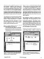
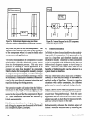
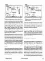
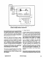
Fabrik
A Visual Programming Environment
DanIngaIIs,ScottWallace, Yu-Ying Chow, Frank Ludolph, Ken Doyle
Apple Computer Inc.
20525h4arianiAvenue
Cupertino, CA 95014
Abstract: Fabrik is a visual programming environment - a kit of computational and user-interface
components that can be “wired” together to build new components and useful applications. Fabrik
diagramsutilize bidirectional dataflow connectionsas a shorthandfor multiple paths of flow. Built on
object-oriented foundations, Fabrik componentscan compute arbitrary objects as outputs. Music and
animation can be programmed in this way and the user interface can even be extended by generating
graphicalstructuresthatdependon other data. An interactivetype systemguardsagainstmeaninglessconnections. As with simple dataflow, eachFabrik componentcan be compiled into an object with access
methodscorresponding to each of the possible paths of data propagation.
1 Kits and Concrete Manipulation
A kit is a set of primitive components, together
with a framework for connecting the components
to do new and interesting things. If objects built
with the kit can in turn be used to augment the
original set of components, then the range of
application becomes very large, limited only by
the capability of the primitive components and the
manner of their interconnection.
The kit approach
has been around for a long time, manifest in the
subroutine libraries of the last three decades.
However, the ability to browse through, and experiment with the available components was extremely primitive, owing to the textual orientation
of underlying computing environments during
those early years.
With the advent of iconic user interfaces, nontechnical users - those not trained to appreciate invisible objects and connections - are able to work
concretely (by pointing at an image) with data and
Prrmlssion
that
the +.CM
and
notice
(‘omputing
or specik
C
to copy
the copies
without
fee all or part
are not made
copyright
is given
Machinery.
notice
that
or distributed
and
the title
of this
material
for direct
of the publication
copying
is by permission
To copy
otherwise,
is granted
commercial
and
its date appear,
of the Association
or to republish,
provided
advantage.
requires
for
a fee and/
permission.
1988 ACM O-89791-284-5/88/0009/0176 $1.50
176
functional components. While iconic interfaces
have had little effect on conventional programming practice, they’ have the potential to greatly
facilitate programming with kits. A box with
connectors can represent a function and its parameter list. The insides of a box can be descriptive of a function or it can be an active piece of the
user interface. A connecting line connotes both
the passageof a value and sequential dependence.
A single intuitive visual metaphor thus encompasses the acts of browsing, testing, connecting,
and finally using the components in the library and
those built from them. We feel that concrete
manipulation can offer users untrained in programming the kind of control that has previously
been available only to professional programmers.
2 Programming with a Kit
The Fabrik library includes computational elements found in most programming libraries, such
as arithmetic and string manipulation, file access,
and logic. These appear as boxes with connectors
which can be wired together to build new functions, This concrete access to functional composition is important, but it is only part of what is
needed to build a complete application.
OOPSLA‘88 Proceedings
September2530.1!398
A look at a modern application program reveals
many idiomatic components which make up its
user interface. Windows, panels with editable
text, lists of selectable items, choice buttons, scroll
bars, and menus are a few that appear fequently.
As with simple computational elements, the Fabrik library provides equally immediate access to
components which provide such high-level capability and which support concrete user interaction.
The remaindei of this section presentsan example
which illustrates the support for browsing, construction, testing and packaging of a complete
application iti Fabrik. Many details relating to the
user interface have been postponed to a later
section to preserve the flow of what is an extremely simple and immediate process.
Goal: To build a simple file browser with the
following capability (see figure If):
User can type a name pattern in one panel,
Second panel shows file names that match,
l Athirdpanelshows thetextofafileiftheuser
selects its name.
Figure la shows a Fabrik Parts Bin in the top
window, and a new Construction Window below
it. The process of building applications in Fabrik
is as simple as dragging copies of components
from the Parts Bin into a Construction Window,
and hooking together the components by their
connectors. In the first figure, a String Viewerhas
been copied from the Front Panel section of the
Parts Bin to the Construction window to allow the
user to type text.
The application in figure la, though trivial, is
already usable. One can type and edit text within
the Sting Viewer, with full support for font
changes and justification. Upon typing <enter>,
the current text appears as output at the pin on the
top but nothing else happens because the output
pin is not connected to anything. If another text
component were wired to the one shown, then the
text would appear in that one as well.
l
l
In figure 1b, the author hastyped the word ‘memo’
in the String Viewer, in order to prepare the
W
FileSize
Figure la. A String Viewer has been dragged from the
Parts Bin to a new Construction Window.
September 25-3!l,1988
Figure lb. The String Viewer has been hooked to a
File Name Matcher. The resulting list of file names is
waiting at the output pin.
OOPSLA ‘88 Proceedings
Figurelc. A List Viewerhasbeen installed and
Figure Id. The selectedfile nameoutput is now hooked
attachedto view the list of filenames.
up via a File Contentsextractorto a StringViewer.
example to search for files with those letters in
their names. He then selected the File Access
category of the parts bin, dragged a File Name
Partern Marcher to the Construction Window,
and hooked that component to the String Viewer.
He also slid the top pin of the String Viewer to one
side for neatness.
In figure lc, the author has obtained aList Viewer
from the Front Panel category of the Parts Bin to
view the list of file names matching the string,
‘memo’. As soon as the File Name Matcher
output is connected to the List Viewer input, the
list of names appears as shown.
lected file asdesired. In roughly five simple steps,
the desired application has been programmed, and
is ready for use. The only problem is that it is still
surrounded by a small scaffold of computational
components and their connections.
Fabrik allows a subregion of each diagram to be
designated as the userframe. This has been done
with the left three panels in figure le, as can be
seen form the heavy border around their periphery. Once the user frame has been designated, a
menu command is available to enter that frame as
shown in the figure. This command instructs
Fabrik to restrict its view to only the designated
In figure Id, the desired functionality of our
sample application is completed by installing a
File Data Contents extractor and a second String
Viewer. These are hooked up in the obvious
manner to view the text when a file name is
selected. The connection appears dashed at this
point in the construction because, with no file
name selected, the value is nil. Fabrik takes care
in this situation to track invalidity SO that no
component is triggered with invalid data.
Figure le shows that after a file name has been
selected, it propagates through the File Data
Contents module, turning the connecting lines
solid, and finally displaying the text of the se-
178
Figure le. The left threepanelshavebeen selected
as the “user frame,” and a menu commandlets one
“enter” that frame.
OOPSLA ‘88 Proceedings
September 2!XO,1988
output, and others (bidirectional pins) are able to
pass data in either direction. The pins can be
moved about the periphery to simplify wiring.
Subject
Fabrik
FigureIf. Theconstructionscaffoldis now hidden
andtheapplicationcanbelaunchedasa reframable
windowreadyfor normaluse.
components, and to make the result available as a
normal window in the environment, capable of
reframing, multiple instances, and all the other
comforts of the supporting environment.
Figure 1f shows our file browser application after
entering the user frame. An application such as
this can easily be assembled in less than five
minutes. Moreover all of the original scaffolding
can later be retrieved for documentation or as the
basis for a revision. This ease of “opening the
hood” adds to the potential reusability of Fabrik
software.
3 About the User Interface
As shown in the preceding example, an author
defines his application by directly manipulating
its visual representation. He selects appropriate
components from the library, places them in a
Fabrik window, and connects them up to achieve
the desired functionality and appearance. A Fabrik component appearsasa rectangle, usually with
one or more connectors. called “pins,” on its
periphery. Some components are purely computational. Others provide user interface functions
within their rectangles. Some pins are used to
gather input for the component, others to channel
September25-30,1988
The Fabrik Parts Bin is organized as a file drawer
with index tabs as shown in figures la and lb.
Components in the library appear here in miniature to savespace. The file drawer idiom usedfor
the Parts Bin was chosen for its rapid accessto
many categories without the complexity of generally nested windows. To use a component, the
author uses the mouse to “grab” it from the Parts
Bin, to drag it over the desired layout window, and
to place it at the desired location by releasing the
mouse button. The “part” being laid out grows to
actual size as it leaves the Parts Bin, to facilitate
layout in the destination window.
Components are connected using a concrete
“wiring” interface, which servesto connect pins of
different components. To wire from a to b, the
author clicks on a, and then clicks again on b. It is
not necessary to wire directly Tom one pin to
another. Each click down establishesa “vertex”in
the wiring diagram, a point where the wire can be
bent or additional wires attached, making it easier
to produce readable diagrams. Numerous features
in the user interface allow this wiring to be
changed for either aesthetic or logical reasons.
As the Fabrik author lays out his components, the
tableau he is creating is always ‘alive’. The
appearanceand behavior of the application being
built are always directly manifest. This is in
contrast to the conventional cycle of editing
source code, compiling, fixing syntax errors, recompiling, linking, loading, then test-running an
application.
If the author is building a new component, as
opposed to a stand-alone application, he will need
to add pins to the window border that serve as
gateways for data to flow into and out of the
component. Internal dataflow semantics of the
component are expressedby wiring between gate-
OOPSLA‘88 Proceedings
179
?CConverter1
Figure 2.a. Bidirectional diagram using two Slider
controls to achievea Fahrenheit-to-Centigradeconverter.
ways and the pins of the sub-components. The
gateways later appearas the pins on the periphery
of the component when it is used to build other
components and applications.
The direct manipulation of components to assert
relationships virtually eliminates syntax errors
from the development process. The only error
possible in building a Fabrik application is to
connect two pins that shouldn’t be connected.
Fabrik checks for incompatible modality (output
to output or input to input), as well as for type
mismatch (seesection 8) before allowing a wire to
be connected. Permission to connect is communicated to the user through apparent attraction and
repulsion during the wiring process.
The attentive reader will notice that the bidirectional pin on the String Viewer in figure la was
coerced to output-only as a result of being connected to the input of the file component in figure
lb. Such directional coercions are handled by
Fabrik automatically.
Fabrik’s user interface, browsing, programming
and debugging support are discussed in full detail
in a companion paper [Ludolph].
180
Figure 2b. Internal diagram for the F/C component
used in the diagram at left.
4
Bidirectionality
In Fabrik we have chosen dataflow as the underlying model of computation. It is presented to the
user in a loop-free and therefore timeless and
declarative model. Dataflow is often considered
to be incompatible with bidirectionality because
bidirectional diagrams appear to have loops in
them. However, with some care, most of the
benefits of bidirectionality can be achieved in a
system based on dataflow.
The key observation about most uses of bidirectional@ is that they are simply a shorthand for
multiple paths of dataflow. Except in complex
situations with subtle constraints, the different
paths may be treated completely independently.
Figure 2 above shows Fabrik diagrams for a bidirectional temperature converter, an example borrowed from Thinglab[Boming]. Both the outer
application and the numerical conversion resolve
simply into a left-to-right flow for input on the left,
and vice-versa for input on the right.
Bidirectionality enhances the intuitive aspect of
Fabrik’s concrete constructions by reducing the
OOPSIA ‘88 Proceedings
September 2530,19t38
amount of wiring as well as by reducing the
number of components needed in the library. We
consider support for bidirectional behavior to be
crucial in any system used to build user interfaces,
since most visual metaphors used for output have
a natural interpretation for input as well.
It is, of course, possible to construct confusing or
ambiguous diagrams with bidirectional components. For instance, if the Times/Divide component in figure 2b were bidirectional at all three
pins, there would be abiguity as to whether a
change in one temperature caused a change in the
other temperature or a change in the conversion
constant! We have chosen to leave Fabrik users
exposed to such possible confusion since the
benefits are so compelling. Possible solutions
range from simple restrictions, such as allowing
no more than two bidirectional pins per component, to employing more powerful techniques asin
Thinglab.
5
Synthetic graphics
We have seen in the foregoing examples how
existing components can be combined to make
new applications and how, through the use of
external connectors, the new applications can act
as components themselves, thus augmenting the
Fabrik library and increasing the power of the
system as a whole. It is obvious that, given a
reasonable basic set of arithmetic and string-handling components, most simple programming
functions can be built up on Fabrik. What is less
apparent at first is that, by including a basic set of
components capable of producing images, Fabrik
assumesthe ability to synthesize any computable
image, In this way, Fabrik applications are as
extensible in their user interfaces as they are in
their numerical and textual manipulations, thus
enabling simple construction of applications and
components such as a bar-chart, a scroll-bar, or an
animation sequence.
September25-a,1988
Fabrilc’s graphical capabilities center around
graphemes, objects that represent images. Graphemes can be simple, such as lines, circles or
bitmaps, or they may be transformed or combined
with other graphemes through overlays, clipping,
rotation and so on. The ability to carry avariety of
different graphical objects on a wire relies critically on the polymorphism of the underlying object-oriented programming language (Smalltalk)
in which Fabrik is implemented.
Some Fabrik components take in non-graphical
data (such as magnitudes, points, vectors, style
specifications) and generate graphemes asoutput.
Thus, a rectangle creator component takes in two
points for its opposite comers and an optional style
(border color, border width, interior color), and
produces a grapheme representing the image of a
rectangle satisfying the input parameters. Various
other such components create lines, ovals,
bitmaps, display text, etc.
A second group of graphical components provide
graphical transformations of general applicability. These include components to scale, translate,
rotate, hide, and invert a grapheme, and to merge
multiple graphemes in various ways.
Graphemes are viewed with graphic viewers.
Each viewer defines its own local coordinate
space. The coordinates carried by the grapheme
define its location in that local space. Whenever
the input changes, the grapheme is redisplayed.
Different graphic viewers offer such features as
automatically scaling their contents, emitting the
final bitmap resulting from the incoming (complex) grapheme, allowing their contents to “pop
up” on top of the current screen layer, and so on.
Finally, interaction is supported in this world of
synthetic graphics by sensor components that
sensitize a grapheme or collection of graphemesto
user input, such as mouse clicks and location
within the bounding box of the grapheme. The
Mouse component hasone output pin (on the right
OOPSLA‘88 Proceedings
181
1
rlider
’ bottomxight
1pleft
Mouse
g%=j
~ttemxight
cuxsoxP0int
I
Q~,
default
Pax
w ConstrainPoint
M
Default
[
IL13
f
NumToPoint a-
Figure 3. A Fabrik diagram computesthe image for the slider in figure 2. The Mouse
componentsensitizestheslider image to supportinputaswell asoutput.
in figures 3 and 4) which emits a sensitized version
of the input grapheme whenever it changes, The
output on the bottomis activated when a grapheme
viewer detectsuser input, at which time it emits the
cursor location. Various sensors support tracking
of different button states, keyboard input, and so
on.
Figure 3 shows the complete Fabrik diagram for
the slider component used in the Fahrenheit-toCentigrade example of figure 2a. Several Iabels
have been made visible, using an option available
in the Fabrik interface. To the right, the slider is
visible in a graphic viewer that automatically
scales the incoming grapheme to fit. The slider is
composed of two rectangular graphemes, a tall
slender one generated by the rectangle creator
grapheme with input points 15@0 and 22@118
(its top-left and lower-right comers), and a horizontal, mouse-sensitized rectangular grapheme
with the size 26@6 whose location is determined
by the program. Below the slider is a small number
component that displays the current value, 13.
182
When the user positions the cursor over the horizontal rectangle in the graphic viewer and presses
the mouse button, the mouse component emits the
viewer-relative
location of the cursor out the bot-
tom pin. The new cursor location causes two
components, NumToPoint and Default, to fire.
Default passesnon-nil inputs through to its output
unchanged. If the input is nil here, the value,
6@50 is output. ConstrainPoint is a user-built
component that limits the Y value of the point to
the range O-l 12 and replaces the X value with 6.
The resulting point is fed unchanged to the origin
pin (upper-left comer) of therectange creator and,
after adding 26@6, to the comer point (lowerright comer). The apparent loop through the
Mouse component is not really a violation of
dataflow, since the cursor output is not triggered
by incoming data, but only by user input.
The new rectangle grapheme created as a result is
sensitized to the mouse, merged with the vertical
rectangle, scaled and displayed. Sensitization to
the mouse means that clicking the mouse button in
OOPSLA ‘88 Proceedings
September 2530,1988
J
Figure 4a. A simple scrollbar diagram. Logic is
provided for rotating when the image is wider than high.
the area of the slide will cause the mouse coordinate to be emitted from the bottom pin of the
Mouse component. NumToPoint is a user-built
component that converts the Y value of the input
point to an integer which is both displayed in the
small number component below the graphic
viewer and passed through the gateway on the
right wall of the window to anything wired to it.
As the user moves the mouse with the button still
pressed, the cycle is repeated.
Bidirectionality permits the slider to be used as an
output indicator as well as an input control. If the
user types into the small number component or a
value flows in through the external gateway, it is
displayed in the number component, flows
through NumToPoint which changes the integer
value into a point, through Default (no change),
through ConstrainPoint, etc., and causesthe small
horizontal rectangle to be repositioned and redisplayed at the appropriate location in the graphic
viewer.
The use of a general algebra of images in Fabrik’s
synthetic graphics adds considerable leverage to
each application. For instance, the scrollbar example in figure 4 produces either a vertical or a
horizontal image, depending upon the aspectratio
of its framed image.
September25-30,1988
Figure 4b. Demonstrating the rotation logic. All
display and mouse-tracking operations are properly
scaled and rotated.
In this case,the background image, another Fabrik
diagram, is scaled and rotated as well asthe slider.
Mouse-tracking coordinates are automatically
transformed through this logic, leaving the scrollbar diagram relatively uncluttered.
From these examples of synthetic graphics it is
apparent how Fabrik deals with other dynamic
media. A musical score or an animation sequence
can equally well be synthesized as a set of primitive elements combined and transformed by other
higher-level functions.
6 The Draw component
As shown above, images can be generated by
connecting various grapheme creators and viewers. A step toward more direct manipulation of
graphical material is the Draw component. Currently a primitive component, it allows the user to
draw graphic objects as in a normal drawing program, while the corresponding Fabrik diagram is
automatically laid down and connected. The user
can further adjust the location and size of the
graphic objects right in the Draw component.
These changesare immediately shown asupdated
point values that are inputs to the grapheme creators. The Fabrik diagram generated is exactly the
OOPSLA‘88 Proceedings
183
3raw 11
qO
Figure5a. TheDrawcomponentautomaticallylays
out diagramsastheusercre+esa drawing.
same as one assembled from scratch, and hence it
can be edited to place additional constraints on the
image.
In the example of figure 5a, the only component
the user actually laid out was the the one marked
“Draw”; the rest of the diagram was automatically
constructed as consequencesof the user drawing
within that component. By tying vertices A and B
together in figure 5b, the top-left comer of the oval
is constrained to have the same location as the
bottom-right comer of the rectangle. Moving
either the oval or the rectangle will causethe other
to resize and maintain the constraint.
7
Iteration
Fabrik components that wish to communicate
with the outside world do so by means of gafeways, pins that provide the link between data
outside the component and data within the component. Most often, these gateways provide a simple
handoff of data from the outside to the inside
184
Figure !%. By editing the generative diagram, the top-left
of the oval is tied to the bottom-right of the rectangle.
(inbound gateways) or from inside the component
to the outside world (outbound gateways).
Certain kinds of gateways can provide iterative
functionality, however. For example, in figure 6,
the inner component expects a collection of numbers to be fed to it. Its inbound collection gateway
on the left disaggregates the collection into its
elements, and the interior of the iterator is fired
once in turn for each element.
On the right of the iterator, a similar outbound
gateway collects up the values it receives from
each firing of the iterator, and when the last iteration is done, it aggregates the data it has received
into a new collection. In the example above, the
collected rectangle graphemes appear as the bar
chart image in the viewer at the bottom.
In Fabrik, every component fms to completion
when instructed to, and iterators are no exception.
The firing of an iterator may involve many complete passesthrough it. The number of passesis
OOPSLA ‘88 Proceedings
September 25-30,lW
larChart
6. Streaminggatewaysprovide iterative capability. Here numbers
are
convertedto rectangles,resulting in a simple bar &art.
Figure
determinedby both the componenttopology and
theactualdatavaluesarriving. Global statewithin
the iterator betweenpassesis preserved by the
semanticsof thegateways,andaparticularkind of
gatewaystructureallows mutablevaluesglobal to
the iteration processto be used.
8 Type System
In orderto validate(or prohibit) wiring attemptsin
Fabrik, a type is associatedwith eachcomponent
pin. Fabrik currently supportsprimitive (record)
types,bundledtypes,array types,andenumerated
types. Primitive typesaredefinedby theprimitive
Within any particular pass through an iterator, data operations in the system, e.g., Number,
strict rules of dataflow scoping prevail so that Boolean, Character, Grapheme, etc. Bundled
predictability and system integrity are assured. types are defined via bundler componentsthat
Fabrik’s approachto iteration in a dataflow con- allow non-homogeneouselement types. Each
text wasinspiredby the ShowAnd Tell Language elementtype canin turn be any of theabovetypes.
[Kimura]. The library includesa full repertoireof The order is defined by the connectionsto the
iterative control gateways, such as conditional prong pins of the bundler component.Array types
terminatorsand the iteration count usedfor hori- must havehomogeneouselementtypes,although
zontal spreadingin the aboveexample.
their size doesnot matter for compatibility. An
enumeratedtype defines a set of actual values
The bar chart exampleillustrates the useof itera- allowed.
tion to producegraphical aggregates.This same
approachis the key to Fabrik’s handling of music Eachprimitive componentassignsa type for each
and animation.
of its pins restricting input andoutput to specified
September 2!XO,lQ88
OOPSIA '88 Proceedings
185
types. When a user places the mouse over a pin,
the pin name and type are shown to assist connection of the correct pin. When a pin is about to be
connected to another pin, type checking is performed. If the two types match, the connection is
allowed; otherwise, a message is displayed in a
status panel and the connection is not made. A
primitive type can only match with other similar
primitive types. A bundled type can match with
another bundled type or array type. Two bundled
types are compatible if their sizes are the sameand
each of the element types matches in order. A
bundled type can match with an array type only if
all the element types of the bundled type are the
same and match with that of the array type. The
result type is the array type. An enumerated type
can match with a primitive type if the primitive
type is the same as the type of the data allowed in
the enumerated type, and data is actually checked
if the primitive typed data is available. Some
components have unspecified types, i.e., their pins
can be connected to any typed pins. Theresult type
of such a connection is the specified type or
remains unspecified if both types are unspecified.
User-built components can have their pins designated with types which are either implicitly inferred from the connections to the corresponding
gateways or explicitly assigned to be some known
types.
Components with unspecified type also have the
ability to propagate types to other pins once a
connection is made to a typed pin. For exampIe,
the selector component that selects from a set of
inputs has all pins designated to be unspecified but
of the same type (except the selection pin which is
of Number type). Therefore when one of these
pins is connected to a typed pin, that type is
propagated to all the other unspecified pins of the
selector, so that other connections to the selector
will only be allowed if they carry that same type.
Similarly when a wire to the selector is cut, its pin
type reverts to unspecified or is inferred from other
pins if there are still other connections. Thus even
188
with the flexibility of unspecified types, every pin
in the complete Fabrik diagrams will be inferred to
have a type. This makes the diagrams simple and
easy to understand.
9
Compilation
Compaction of representation and speedof execution are the masons for undertaking compilation in
Fabrik. The task of compilation here is to map the
semantics of a diagram, as embodied in its interpretive behaviour when manipulated in the Fabrik
layout editor, into the definition of a new class
whose instances behave as specified by the diagramThe current version of Fabrik uses the ability of
Smalltalk to compile new classes and methods
dynamically, and hence the code generated, as
illustrated below, consists of Smalltalk methods.
Every Fabrik diagram contains a particular set of
subparts (themselves all Fabrik components) and
a particular set of what may be thought of as data
slots, where each data slot corresponds to the
datum beneaththe “copper” of one particular wire.
Instances of a compiled class representing a Fabrik diagram hold, in instance storage, the subparts
and the data slots. Compiled methods mostly read
from and store to theseinstance variables, making
for efficient code.
The consequences of any data perturbation in a
Fabrik diagram can be mapped, after a topological
sort, into a linear dataflow path - a sequenceof
subparts to be traversed in a specified order and in
specified manners. The compiled method representing any particular path carries out the corresponding series of traversals.
Compilation example 1: The FtoC
Looking at the internal structure of the FtoC
component shown in section 4, we notice that the
diagram has four subcomponents - the two bidi-
OOPSLA ‘88 Proceedings
Sqlemba
2!30,1988
rectional arithmetical components TimesDivide
and PlusMinus (both of them in turn being components built with Fabrik) and the two boxes that
generate the conversion constants 915 and 32.
Additionally, there can be seentu be five diifferefit
pieces of data flowing in the wires, starting Wh,
at center left, the datum that representsthe Centigrade value, and including two invariant data
constants, one intermediate result, and the Farenheit value.
example, in method pl :, the call
c3 pl: x
will result in an updated value appearing on instance variable v3. In this case, ~3 represents an
intermediate result, which will be seen to be used
subsequently as an input argument in the call
c5 pl: v3.
The calls to export:outChannel: handle exporting
of values computed during traversal to the world
outside for the FtoC itself.
Compilation example 2: The FCConverter
After compilation, the FtoC would be represented
by an object with the instance structure shown in
figure 7a. Note that there is one instance variable
for each constituent subcomponent, and one instance variable for each data slot in the
component’s scope.
Note that part of the responsibility of the traversal
code of any component is to export its computed
output data to the surrounding domain. Thus, for
nst
WI
.!!mL
Cl
C-2
C3
c4
Vl
v2
V3
v4
VS
Turning to the FCConverter, we have an even
simpler diagram, and hence an even simpler instancestructure. In this casethere are no traversal
methods, since no data arrives from external
components connected to the edge of this one.
Instead, one needs “radiation” methods, which
propagate data originating spontaneously from
within nested subcomponents. Note that in this
example, either of the sliders can generate new
dataflow by being stimulated, via the user interface, from either keyboard input or mouse actions.
e TimesDivide
component
generates the constant 9/S
e Plusnlnus component
generates the constant 32
holds Centigrade velue
holds the constant 9/S
holds intermediate
result
holds the constsnt 32
holds Ferenhott value
lnst ver
name
Cl
c2
I.3
between
PluSlllnus
b TimesDivIde
Vl
v2
Figure 7a Instancestructurefor FtoC application
deocriptton
I
the left Sllder
the FtoC
the right Slider
holds Centlgrade value
holds Forenheit value
Figure 8a Instancestructurefor compiled FCConverter
pi : x “called when a new Centigrade value
arrives from the left”
c3 pl : x. “traverse the Times/Divide from left
c5 pl : v3. “traverse the Plus/Minus from left”
self export: v5 outchannel: 2
“ship V5 value out output channel 2”
elpl : x ‘rakes value x, emitted from the left
slider, and propagates it rightward”
c2p1:x.
“convert from Centigrade to
Farenheit; load result on v2”
c3 pl : v2 “sends the value through the
right slider’
p2: x “called when a new Farenheit value
arrives from the right”
c5 p2: x. “traverse the Plus/Minus from right”
c3 p2: v3. “traverse the Times/Divide from tight”
self export: vi outchannel: 1
“ship Vl value out output channel 1"
e2pl: x “takes value x, emitted from the right
slider, and propagates it leftward”
c2 p2: x. “convert from F to C; will leave
computed C value on vi”
cl pl : vl “sends the value through the
left slider
Figure 7b Compiled methodsfor FtoC application
September25-30.1988
Figure 8b
OOPSlA‘88 Proceedings
Compiled methods for FCConverter
187
Note that in this example, the methods p 1: and p2:
invoked for subcomponent named c2, which is the
FtoC, are precisely the methods pl: and p2: illustrated for the FtoC in the previous example,
Compilation example 3: The Slider
The Slider, shown in figure 3, combines elements
of the two preceding compilation examples, in that
it must respond both to traversal (new value arriving on an external input pin) and to internal change
from the user interface (user drags the slider’s bar,
or types in a new value in the slider’s numeric
readout panel). Since it has a considerably more
complex internal structure, we shall only illustrate
the instance structure (figure 9a), one traversaI
method, and one radiation method (figure 9b).
Note that thereis a commonsubsequenceof six instructions
between the two illustrated methods. Combining such
common subsequencesinto separatemethodsis just one of
a numberof possibilitiesfor codesizecompressionand code
optimization arising from the basic schemeillustrated.
nst vet-
description
name
Cl
c2
CS
c4
C5
C6
c?
CB
c9
c 10
CI 1
c I2
cl3
c I4
cl5
c 16
4 Point component (1500)
4 Point component (22* I 18)
4 RectangleCreator
4 Graphemetlerger
4 Mouse component
4 NumToPoint component
an Expression component (6@50)
4 Default component
an Exprasslon component (0)
4n Expression component ( 1 12)
4 ConstmtnPoint
component
an Expression component (2606)
an Adder
4 RectangleCreator
4 Dlsplsy component
an Integer component
Vl
v2
V3
v4
VS
vb
v7
v8
v9
VlO
VII
VI 2
~15
VI 4
~15
vt6
V I?
VIE
v I9
1500
220118
default style for fixed rectangle
fixed rectangle grapheme
grapheme output from HouSe COmpOIWnt
eenmr locatlon from blouse component or from NumToPolnt
button-state
output from House component
selected or default point
6050
0
1 I2
constmlned point
2606
comer far movable rectangle
delsult style formweblr
rectangle
movable-rectangle
grapheme
ffl8q8d Qrsphsttl8
bitmap out from Dlsplag component
computed mognltude
Figure 9a Instancestructurefor compiled Slider
pl: x “invoked when a new magnitude enters the Slider from outside”
“textual display of value at base of slider
cl6pl: x.
“convert to a poinr
c6 p2: x.
“use
6@50 if nil comes in from outside”
c8 p2: v6.
“constrain
point to fit within slider”
cl 1 p3: v8.
“compute corner for movable rectangle”
cl3 pl: ~12.
“generate grapheme for movable rectangle’
c14pl:v12p2:v14p3:vl5.
“bundle rectangle with an input sensor’
c5 pl: ~16.
“now merge with the fixed vertical rect”
c4 p2: v5.
“display the merged grapheme”
cl5 pl: v17.
e5p2: x “invoked upon mouse-click in the slider’s display area”
“use 6@50 if nil comes in from outside”
c8 p2: v6.
“constrain point to fit within slider”
cl 1 p3: v8.
“compute corner for movable rectangle”
cl3 pl: ~12.
“generate grapheme for movable rectangle”
cl4 pl: VI2 p2: VI4 p3: v15.
“bundle rectangle with an input sensor”
c5 pi : ~16.
“now merge with the fixed vertical rect”
c4 p2: v5.
“display the merged grapheme”
cl5 pl: v17.
“convert to a number”
c6 pl : x.
“display magnitude at base of slider”
cl6 pl: v19.
Figure 9b Two methodsfor compiled Slider
188
OOPSL4 ‘88 Proceedings
September 25-30,1998
pl:x
*Pr&iteration processing”
c6 import: x.
c7 prepareTolterate
“import the new collection and set up”
“initialize the collection-out gateway”
“Actual iteration”
self iterate:
[cS fireonce.
15 fireonce.
c8 p2: VlO p3: v9.
c3 pl : v4 p2: v3 p3: v7.
c4 pi : vi p2: v8.
c2 pl : v6 p2: v2.
c7 pl : vq.
“repeat the following block until done...”
“inject the next collection element”
“inject the current tick-count”
“fire the bundler component”
“create a new rectangle”
“evaluate a l b
“translate the grapheme”
“accumulate at the collection-out gateway”
“Post-iteration processing”
“export the resulting array”
c7 export
Figure 10 Compiled method involving iteration
Compilation example 4: Iteration
Compilation of components that iterate requires
extra mechanism. Iterating traversals are decomposed into three processing phases: pre-iterative
processing, actual iteration, and post-iterative
processing. The compiled code for the actual
iteration features invocation of “self iterate:” with
a block as its argument. The block describes a
single traversal, and its contents are similar to
other traversal code, with special code added to
carry out the functions of the iterating gateways.
For example, here is the code compiled for firing
the iterator illustrated in the BarChart example in
Section 7, with “x” representing the new array to
be charted:
bine these components interactively to build new
Iibrary components and finished applications.
The examples and discussion above detail
Fabrik’s contribution in the areasof bidirectionality, synthetic graphics, iteration, type checking
and compilation.
Fabrik began with an attempt to mix arbitrary
layout and cell types in an object-oriented spreadsheet. The spreadsheetapproach brokedown with
the complex expressions needed for synthetic
graphics and other generative structures. The
wiring approach addressed this problem and also
opened the way for bidirectional constructions.
10 History and Status
The initial Fabrik prototype was developed in
Smalltalk within the Advanced Technology
Group of Apple in 1985, and was demonstrated
widely within Apple in Spring of 1986. The type
system was added during the Winter of 1987 and
compilation was completed in the Spring of 1988.
Experience with Fabrik suggeststhat a successful
visual programming kit requires only three things:
Specification of an effective visual and computational interface for each component, interactive
accessto an interesting (network) library of existing components, and the ability to use and com-
An important next step in this investigation is one
of scale: to assemble a library sufficient to accomodate alarge class of applications, and to support
networking of this library so that many people can
borrow from and experiment with each other’s
work.
Sepfember 2.530,1988
OOPSLA ‘88 Proceedings
189
References
[Kimura] T.D. Kimura and P. McLain,
“Show and Tellm User’s Manual,”
Tech. Report WUCS-86-4, Department of
Computer Science, Washington University,
St. Louis, MO, March 1986.
[Boming] A.H. Borning, ?‘hingLab,
A Constraint-Oriented Simulation Laboratory,”
Tech. Report SSL-79-3,
Xerox Palo Alto Research Center,
Palo Alto, CA, July 1979.
[Smith] D.N. Smith,
“InterCONS: Interface CONstruction Set,”
Tech. Report RC 13108,
IBM T.J. Watson Research Center,
Yorktown Heights, NY, September 1987.
[Labview] “LabVlE~
Demonstration Manual,” National Instruments, Corp.
Austin, Texas, 1987.
[Gould] L. Gould and W. Finzer,
“Programming by Rehearsal”,
Tech. Report SCL-84- 1,
Xerox Palo Alto Research Center,
Palo Alto, CA, May 1984.
[Ludolph] F. Ludolph, D. Ingalls, Y. Chow, S.
Wallace, “The Fabrik Programming Environment,” to be published in proceedings of @e
IEEE Workshop on Visual Languages, 19@$.
[Metaphor] “Metaphor Capsule Development,”
Metaphor Computer Systems,
Mountain View, CA,
OOPSLA ‘88 Proceedings
September 25-30,1998