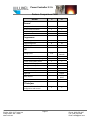
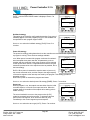
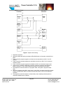
1
Radak Power Controller II Series Manual Rev2.2 Power Controller II / II+ PO Box 1879, 515 Tucker Ave Friday Harbor, WA. 98250 www.luxel.com Phone: (360) 378-4137 Fax: (360) 378-4266 Email: [email protected] Power Controller II / II+ Table of Contents Introduction ...................................................................................................................................... 1 Specifications ............................................................................................................................... 3 Operation .................................................................................................................................. 3 Electrical ................................................................................................................................... 3 Mechanical ............................................................................................................................... 3 Feature Comparison Chart .............................................................................................................. 4 General Description ......................................................................................................................... 5 Installation........................................................................................................................................ 6 Mechanical Installation................................................................................................................. 6 Electrical Connections ................................................................................................................. 6 Power input .................................................................................................................................... 7 Operation ....................................................................................................................................... 12 Overview .................................................................................................................................... 12 Primary button functions:........................................................................................................ 13 Basic Controller Operation ..................................................................................................... 13 Controller Displays ................................................................................................................. 14 Access Levels......................................................................................................................... 14 RADAK Power Controller configuration ....................................................................................... 18 Accessing the configuration level ........................................................................................... 18 Instrument Configuration ........................................................................................................ 19 Disabling manual operation .................................................................................................... 19 Enabling gain scheduling ....................................................................................................... 19 Process Value Configuration .................................................................................................. 19 High temperature limit ............................................................................................................ 20 Programmer Configuration ..................................................................................................... 21 Limiting output power ............................................................................................................. 22 Setpoint Limits ........................................................................................................................ 23 Programming.............................................................................................................................. 23 Program Behavior .................................................................................................................. 23 Sample Program .................................................................................................................... 24 Running Programs ................................................................................................................. 26 Stopping Programs ................................................................................................................. 26 Modifying Program Parameters.............................................................................................. 26 Tuning..................................................................................................................................... 27 General notes on tuning ......................................................................................................... 27 Controller high cutback setting ............................................................................................... 27 Gain scheduling ...................................................................................................................... 28 Auto tune ................................................................................................................................ 28 Adaptive tune.......................................................................................................................... 28 Automation with the RADAK II+ power controller ........................................................................ 29 I/O Points: ............................................................................................................................... 29 Configuration: ......................................................................................................................... 29 Example Control Schemes: ....................................................................................................... 30 Goal ........................................................................................................................................ 30 Equipment .............................................................................................................................. 30 Assumptions ........................................................................................................................... 30 RADAK Power Controller II+ ......................................................................................................... 34 Deposition Controller ..................................................................................................................... 34 Maintenance .................................................................................................................................. 35 Troubleshooting ............................................................................................................................. 36 Symptom ..................................................................................................................................... 36 Possible causes ............................................................................................................................. 36 Correction .................................................................................................................................... 36 PO Box 1879, 515 Tucker Ave Friday Harbor, WA. 98250 www.luxel.com Phone: (360) 378-4137 Fax: (360) 378-4266 Email: [email protected] Power Controller II / II+ Appendix I .................................................................................................................................. 37 Appendix II ................................................................................................................................. 38 PO Box 1879, 515 Tucker Ave Friday Harbor, WA. 98250 www.luxel.com Phone: (360) 378-4137 Fax: (360) 378-4266 Email: [email protected] Power Controller II / II+ Introduction Thank you for choosing a RADAK Power Controller II. We hope that you will find it simple to operate while offering advanced control options. Although specifically designed and optimized for controlling one of Luxel’s line of RADAK evaporation furnaces, your RADAK Power Controller II is also well-suited for many other power control applications, such as lamps, filament heaters, etc. Instructions for connecting your RADAK Power Controller II to these auxiliary devices is included in an appendix. *Caution! Installation must be carried out by qualified personnel. Failure to install or operate this power controller in the manner described in this manual could result in injury of the operator and/or failure of the controller to meet its stated specifications. *Caution! Always unplug the power cord from the rear panel before removing any of the cabinet covers or components. Line voltage is present on exposed connectors and components inside the cabinet, and is capable of causing injury or death. This manual is organized in a way that you should find convenient to look up the specific information you need quickly and easily. Chapter 1 provides a general overview of the design of the power controller. Chapter 2 describes the installation procedures necessary to safely place the power controller into operation. Operation of the power controller is covered in Chapter 3. The layout of this chapter is by task grouping (organized by specific results to be achieved), so that you can quickly find out how to accomplish a specific goal. It is also useful to read over this chapter to acquire a feel for the general method of configuring, programming, and operating this power controller in its different operating modes. Chapter 4 covers maintenance of the power controller. Troubleshooting follows in Chapter 5, which includes wiring diagrams and replacement parts specifications. Appendix I is included to assist those who desire to connect their power controller to devices other than RADAK evaporation furnaces. It covers the information necessary to assess the load for its suitable control, configure the power controller for a different sensor feedback, and tune the controller for the load’s response. Warning *Caution! Installation must be carried out by qualified personnel. Failure to install or operate this power controller in the manner described in this manual could result in injury of the operator and/or failure of the controller to meet its stated specifications. *Caution! Always unplug the power cord from the rear panel before removing any of the cabinet covers or components. Line voltage is present on exposed connectors and components inside the cabinet, and is capable of causing injury or death. PO Box 1879, 515 Tucker Ave Friday Harbor, WA. 98250 www.luxel.com Page 1 Phone: (360) 378-4137 Fax: (360) 378-4266 Email: [email protected] Power Controller II / II+ Warranty Your RADAK Power Controller II is warranted to be free of defects due to materials or workmanship for 1 (one) year from date of purchase. This warranty excludes damage caused by improper installation and intentional or inadvertent misuse (e.g. operating into an unsuitable load). In the event of a warranty claim, Luxel Corporation reserves the right to either repair or replace the unit at our discretion. PO Box 1879, 515 Tucker Ave Friday Harbor, WA. 98250 www.luxel.com Page 2 Phone: (360) 378-4137 Fax: (360) 378-4266 Email: [email protected] Power Controller II / II+ Specifications Operation Temperature range: ................................ 0 to 1500 °C (type C), 0 to 1200 °C (type K) Temperature resolution: ......................... 0.1 °C (0 to 999.9 °C) 1 °C (1000 to 1500 °C) Temperature units:.................................. °C, °F, K (selectable) PID constants: ........................................ 2 sets Environment:........................................... 0 to 55 °C operating ambient, 10 to 70 °C storage 5 to 95 % relative humidity, non condensing. Not suitable for use at elevations greater than 2000 m, or in explosive or corrosive atmospheres Electrical Input power: ............................................ 115 Vac/60 Hz 12 A max Fuses: ..................................................... System – 10 A fast blow; Controller – 2 A fast blow Thermocouples: ...................................... Type C (0 to 1500 °C), or type K (0 to 1200 °C) Furnace outputs: ..................................... 0 to 40 Vac, at 0 to 30 A Mechanical Enclosure: ............................................... 8.43 W x 5.25 H x 15.07 L (inches, excluding handles) PO Box 1879, 515 Tucker Ave Friday Harbor, WA. 98250 www.luxel.com Page 3 Phone: (360) 378-4137 Fax: (360) 378-4266 Email: [email protected] Power Controller II / II+ Feature Comparison Chart Model: II II+ 2404 x x 1 2404 x x 1 Programmer Stored Programs Program Segments Stored programs can be linked 1 8 4 16 x I/O General Incorporates Eurotherm Model # RS 232 Communications Auto‐Tune algorithm Output Channels Control schemes PID 1 PV, external x x x x x x x 3 input 2 SPST, 1 SPDT PID, external PC Interface Eurotherm iTools software for configuration and control x x Analog inputs PO Box 1879, 515 Tucker Ave Friday Harbor, WA. 98250 www.luxel.com 1 PV Software‐selectable input source All common thermocouple types Custom linearization profile All standard RTDs, pyrometers Voltage, current inputs User calibration External control inputs Digital I/O x x x x x x Relay outputs Page 4 Phone: (360) 378-4137 Fax: (360) 378-4266 Email: [email protected] Power Controller II / II+ CHAPTER 1 General Description The RADAK Power Controller II is constructed of three primary components, carefully selected to work together and provide complete functionality. These components consist of a temperature controller, a phase angle firing SCR, and an output transformer. The remaining components inside the power controller enclosure support the operation of and add functionality to the primary components. These components include switches, relays, connectors, and an auxiliary power supply. The temperature controller is a Eurotherm model 2404. This unit, described thoroughly in the included Eurotherm user manual, accepts a thermocouple signal as a feedback input and computes an output level which will achieve the desired setpoint value. The control scheme used by the temperature controller is a PID (Proportional, Integral, Derivative) algorithm, widely used for general control applications. By adjusting the three terms, P, I, and D, along with output scaling and power cutback to reduce overshoot, the algorithm can be tuned for any temperature range and device response to provide a rapid rise to the setpoint temperature with little overshoot and quick temperature stabilization. In addition, the model II controller allows programming a time/temperature profile, so that the temperature can be made to follow a sequence of step changes, linear slopes, and dwell periods. After computing an appropriate output level, the temperature controller sends a signal to the phase angle firing SCR to regulate the line voltage being applied to the transformer. Phase angle firing is used to provide a consistent and steady furnace temperature. An alternative to phase angle firing, zero-crossing SCRs are much less expensive, but produce small oscillations of the furnace temperature at steady state. This is due to the low thermal mass, and hence quick response, of the RADAK evaporation furnace line. The third important component is the isolation transformer. The transformer is installed on the output of the SCR and serves two functions. First, the transformer scales the output voltage from 0-120 Vac (or 0-240 Vac) to 0-40 Vac. In addition, the transformer serves to isolate the furnace (or other resistive load) from the power controller. This reduces the chance of ionic conduction occurring in the source, which will appear as a short circuit. PO Box 1879, 515 Tucker Ave Friday Harbor, WA. 98250 www.luxel.com Page 5 Phone: (360) 378-4137 Fax: (360) 378-4266 Email: [email protected] Power Controller II / II+ CHAPTER 2 Installation This chapter describes the installation procedures for connecting a RADAK Power Controller II to a vacuum system containing a RADAK evaporation furnace. For connection to other devices, it is recommended that you read this chapter first, as it contains complete installation instructions. Also read Appendix I, which contains some general guidelines for controlling other devices. *Caution! Installation must be carried out by qualified personnel. Failure to install or operate this power controller in the manner described in this manual could result in injury of the operator and/or failure of the controller to meet its stated specifications. *Caution! Always unplug the power cord from the rear panel before removing any of the cabinet covers or components. Line voltage is present on exposed connectors and components inside the cabinet, and is capable of causing injury or death. Mechanical Installation The RADAK Power Controller II series instruments are provided in a bench top configuration. Rack mounting hardware is available to enable the power controller to be mounted in a standard 19 inch instrument rack. This hardware consists of steel angle brackets with bolt-on handles and mounting screws. To mount a single cabinet into an instrument rack, a rack mount adaptor is available or it will be necessary to fabricate a metal support plate to secure the inboard side of the cabinet. This consists of a simple 5¼ inch by 9¼ inch strip of metal (0.125 inch thick aluminum will work well) containing holes to bolt to the power controller mounting bracket on one side and the instrument rack on the other. Two RADAK Power Controller II series instruments can be mounted side-by-side using only 5¼ vertical inches of rack space. Electrical Connections The following figure shows the rear panel of the RADAK Power Controller II. PO Box 1879, 515 Tucker Ave Friday Harbor, WA. 98250 www.luxel.com Page 6 Phone: (360) 378-4137 Fax: (360) 378-4266 Email: [email protected] Power Controller II / II+ II+ II+ Component Power input System fuse Controller fuse RS 232 Thermocouple Power output SCR control input (II+) Supplied Accessories Power cable 10 A fast blow 5x20 mm, +spare 2 A fast blow 5x20 mm, +spare None – use DB9 serial or adapter 1 ea. 6 ft extension cables Connector w/6 ft output cable None – use male BNC cable Function Mains voltage input Protects entire instrument Protects temperature controller Computer/controller access Feedback of measured temperature Power to external device (furnace) External device (deposition controller) SCR control input Power input. The input power requirement for the RADAK Power Controller II is a single 15 Ampere circuit at 115 Vac, 60 Hz, via a standard three-prong grounded outlet (other input voltages and frequencies can be optionally supplied). System fuse. This fuse, installed on the main input line (hot) conductor, protects the entire instrument from an overcurrent situation. Input power to all components inside the RADAK Power Controller II passes through this fuse first. Its primary purpose, however, is to limit the current available to the output transformer and associated wiring and components. The correct replacement fuse is 4 x 20 mm, 10 Amp, 250 Volt, fast blow. It is important that replacement fuses match these specifications exactly so that the system and operator are adequately protected. *Warning! – installing a fuse bearing a different rating from the specified fuse rating can result in damage to the power controller, wiring, and any attached device, or cause a fire. PO Box 1879, 515 Tucker Ave Friday Harbor, WA. 98250 www.luxel.com Page 7 Phone: (360) 378-4137 Fax: (360) 378-4266 Email: [email protected] Power Controller II / II+ Controller fuse. This fuse, installed on the line (hot) conductor supplying power to the temperature controller and low voltage power supply, protects these components from an overcurrent situation. The correct replacement fuse is 4 x 20 mm, 2 Amp, 250 Volt, fast blow. It is important that replacement fuses match these specifications exactly so that the system and operator are adequately protected. *Warning! – installing a fuse bearing a different rating from the specified fuse rating can result in damage to the power controller, wiring, and any attached device, or cause a fire. RS 232. This DB9 connector is an industry standard for serial communications with a personal computer. Two-wire communications with a grounded common, following the RS 232 electrical standard, are supported by the temperature controller. All functions and settings of the controller are accessible through this link. The connection with a personal computer can be made using a straight-through cable terminated on one end with a DB9 male connector, with the other end as appropriate to the computer. Thermocouple. The thermocouple provides feedback from the furnace or other attached device as to its current temperature, which is the value of primary interest. The temperature controller uses the error between the desired (setpoint) and measured temperatures to compute a new output power level to apply to the heater coil. It is thus important to install the thermocouple cable correctly so that the measured value accurately represents the furnace crucible temperature. A thermocouple cable has been supplied with the power controller, comprised of 6 feet of the proper type of extension wire fitted with a mating connector for the rear panel jack. This wire should be routed away from sources of electrical noise, such as high frequency power supplies and electric motors. If the length must be increased, it is preferable to replace the cable with a single length rather than splicing an additional length of cable to the supplied cable. If the required length is fairly long (>20 feet), it is better to use a shielded thermocouple cable to reduce its susceptibility to electrical noise. Finally, if the required length is very long (>50 feet), a signal retransmitter or amplifier should be used. A much better solution to these applications is to site the power controller closer to the furnace, and operate the controller remotely using either RS 232 communications or the provided digital I/O functions. The unprepared thermocouple extension cable ends must be connected to the vacuum feedthrough to which the furnace thermocouple is connected. This vacuum feedthrough should be compatible with the thermocouple type (C or K). Proper vacuum feedthroughs for thermocouples are readily available from vacuum system parts suppliers, or are supplied with the optional installation kit from Luxel Corporation or its distributors. Power output. The heavy (10 gauge) output cable delivers the current supplied by the power controller to the furnace. This cable size is specified to handle the maximum safe output current of the power controller, even though in normal operation the current flow will be considerably less. It is very important to consider the resistance and current when connecting the power controller to a device other than a RADAK evaporation furnace. Please refer to Appendix I for details of these calculations. One end of the output cable is supplied with a mating plug to the rear panel receptacle, the other end is supplied unprepared. The unprepared cable end should be connected to the feedthrough by whatever means are appropriate for the feedthrough. Be careful, however, to connect it in such a way that the full current load will not overheat the connection: i.e. use a large enough connector for the current and make sure the crimp or solder joint is properly made. PO Box 1879, 515 Tucker Ave Friday Harbor, WA. 98250 www.luxel.com Page 8 Phone: (360) 378-4137 Fax: (360) 378-4266 Email: [email protected] Power Controller II / II+ The recommended feedthrough style is a pair of ¼ inch solid copper rods penetrating the vacuum system. The output cable can then be connected to the rods using copper clamping connectors secured to the feedthrough rods, with heavy crimp rings providing the attachment point of the cable conductors to the copper rods. This is the connection method provided by the optional installation kit. Remote I/O Many aspects of the operation of the RADAK Power Controller II+ can be initiated, controlled, or monitored remotely through the use of the Remote I/O cable. Alarm Changeover Relay Outputs Functions for I/O cable 1– alarm changeover relay Wire Marking Wire Color Black 0 Red 1 Green 2 Function Common Relay NO Relay NC The alarm changeover relay can be configured to become active upon the temperature controller sensing certain events, such as the process value (furnace temperature) exceeding a preset bound. This function is especially useful when operating the power controller in rate control mode. The temperature controller can continue to monitor furnace temperature and activate the relay if the temperature rises too high, as would happen if the source charge were depleted and the deposition controller called for a higher output power in an attempt to bring the deposition rate back into spec. The alarm relay would thus be a signal to the deposition controller to shut down the process and alert an operator. This relay is a changeover relay, meaning it has both normally closed (NC) and normally open (NO) contacts. When inactive there is continuity between NC and common, and not between NO and common. When active there is continuity between NO and common, and not between NC and common. Digital Inputs Functions for I/O cable 2 – digital input Wire Marking 0 1 2 3 Wire Color Black Red White Green Function Common Input 1 Input 2 Input 3 The digital inputs may be assigned to trigger various events but come pre-configured for program select. The following illustrates the use of remote program select. Selection is initiated by making electrical contact between the common (0) Program Activation wiring All open 1 Black (0) + White (2) 2 Black (0) + White (2) + Red 3 (1) Black (0) + Green (3) 4 Functions for I/O cable 4 – digital input Wire Marking 0 PO Box 1879, 515 Tucker Ave Friday Harbor, WA. 98250 www.luxel.com Wire Color Black Page 9 Function Common Phone: (360) 378-4137 Fax: (360) 378-4266 Email: [email protected] Power Controller II / II+ 1 2 Red Green Input 1 Input 2 The digital inputs can be used to initiate various events in the temperature controller, such as starting and stopping programs, selecting a specific program to run, or selecting a different PID set to use. A full list of these possible uses can be found in the accompanying Eurotherm 2404 manual. To use this capability, the temperature controller must be configured with the intended function of each input. Then connecting the numbered input wire with the common wire causes the programmed function to occur, or become active. Removing the connection causes the normally open, or default function, to occur. Note that more than one input wire can be simultaneously connected to the common wire, so that functions can be used together when it makes sense to do this Functions for I/O cable 3– relay output Wire Marking 0 1 2 3 Wire Color Red White Green Black Function Relay 1 Relay 1 Relay 2 Relay 2 The relay outputs are similar to the alarm changeover relay, with the exception that the two relays do not offer both normally closed and normally open contacts. They can be configured for either NO or NC operation to simply connect or disconnect one side to the other when active, and reverse this when inactive. The relays can be configured to provide an event output (explained further in the Event outputs below) which is activated by a running program in the temperature controller. PO Box 1879, 515 Tucker Ave Friday Harbor, WA. 98250 www.luxel.com Page 10 Phone: (360) 378-4137 Fax: (360) 378-4266 Email: [email protected] Power Controller II / II+ Remote Control Functions Functions for I/O cable 5 –external SCR control select (II+) Wire Marking 0 Wire Color Black 1 Red Function External SCR control select common External SCR control select The remote control functions allow an external system controller to operate the internal control relays that select whether the SCR is controlled by the temperature controller or by an outside device such as a deposition monitor (II+). PO Box 1879, 515 Tucker Ave Friday Harbor, WA. 98250 www.luxel.com Page 11 Phone: (360) 378-4137 Fax: (360) 378-4266 Email: [email protected] Power Controller II / II+ CHAPTER 3 Operation Your RADAK power controller has been designed for maximum versatility, and offers two different operating configurations. The first, and most basic, is pushbutton operation. In this mode all parameters are set and any programming is done using the buttons on the front of the Eurotherm 2404 temperature controller along with the switches provided on the front and rear panels of the power controller. While this operating mode provides access to all of the features of the controller, it is more time consuming to enter programs and requires manually starting the controller. A second operating mode, RS 232 serial, is also available. If your RADAK power controller is connected to a personal computer running the Windows® platform, you can use the Eurotherm iTools software to set all controller parameters as well as to easily enter sophisticated time/temperature profiles. The most current version of iTools is a free download available from Eurotherm at (http://www.eurotherm.com/itools/). If you are connected to a different type of computer, or a PC not running the Windows® platform, you can either use a standard communications program in local mode to operate the power controller, or you can construct custom software to operate the controller. This chapter has been arranged by function to provide both the person commissioning and the person operating the power controller with the most efficient means of obtaining instructions for a specific operation or setting. It begins by providing general instructions on the three operating modes described above: front panel operation, RS 232 communications, and digital control. This is followed by a section addressing controller setup – designating functions to be attached to specific inputs and outputs, and setting valid ranges and limits. Finally, a section is directed at the operator, and covers profile programming and other operator functions. Overview There are six front panel buttons on the Eurotherm 2404 temperature controller. By pressing these buttons in the proper sequence all of the controller functions can be accessed, all parameters can be accessed and changed, and any allowable temperature profile can be programmed. The six buttons are distinguished by symbols molded into them (or printed near them), and have specific functions associated with each. The display consists of two lines of numbers. The upper (larger) number shows by default the current measured temperature as read by the thermocouple. The lower, smaller, number displays the current setpoint value. Note that these displays represent many other values during configuration and programming, with the current meaning of a display frequently indicated by a mnemonic. PO Box 1879, 515 Tucker Ave Friday Harbor, WA. 98250 www.luxel.com Page 12 Phone: (360) 378-4137 Fax: (360) 378-4266 Email: [email protected] Power Controller II / II+ Primary button functions: 2404 OP1 OP2 22.0 20.0 SP2 REM AUTO MAN RUN HOLD c or d raise or lower the parameter that is currently in focus, by default the temperature setpoint. scroll through the different parameter lists 4 cycle through the various parameters in a given list man/auto toggle the controller between manual mode and auto mode. In manual mode, the arrow keys serve to raise or lower the output power directly, rather than using the built-in PID control algorithm. In auto mode the arrow keys allow changing the temperature setpoint, which the PID algorithm attempts to follow. run/hold toggles between running and pausing the current program. Holding this button in for several seconds resets a running program. Basic Controller Operation Switch on the power to the controller. The controller runs through a self-test sequence for approximately three seconds and then displays the measured temperature, or process value, in the upper readout and the target value, or process setpoint, in the lower readout. This is called the home display. You can return to this display at any time by simultaneously pressing the 4 and buttons. • • • Automatic mode- Output is automatically adjusted to maintain the process value. Manual mode- Output power is controlled directly by the operator. Program mode- Output power and process setpoint are automatically adjusted by the controller. Automatic Mode The RADAK Power Controller is normally operated in automatic mode. If the MAN light is on, press the AUTO/MAN button to select the automatic mode. In the home display, both the process value and process setpoint are 2404 OP2 OP1 shown. The setpoint is adjusted by pressing the c or d buttons. Two seconds after releasing either button, the display blinks to show that 22.0 the controller has accepted the new value, and the controller adjusts output power as required to obtain and maintain the new setpoint. The 20.0 RADAK Power Controller’s power response characteristics are determined by the PID and output parameters described in the Tuning SP2 REM section below. RUN AUTO MAN HOLD OP1 will light whenever output 1 is on indicating that the controller is applying power. Manual Mode Manual mode is used when direct operator control of output power level is desired. To operate the controller in manual mode, press the AUTO/MAN button to toggle from auto to manual mode. The MAN light will illuminate indicating manual mode operation. The lower display now indicates the percent power output by the controller. Output can be adjusted by pressing the c or d buttons. NOTE: Extreme caution should be exercised when using the RADAK Power Controller in manual mode as power is applied without regard to process value. Operating without the RADAK Power Controller’s PID can result in potentially damaging temperature extremes. Manual mode may be disabled as explained in the Disabling manual operation section on page 19. PO Box 1879, 515 Tucker Ave Friday Harbor, WA. 98250 www.luxel.com Page 13 Phone: (360) 378-4137 Fax: (360) 378-4266 Email: [email protected] Power Controller II / II+ Program Mode Perhaps the most convenient method of operation is the program mode. Stored programs specifying setpoints, ramps and dwells may be used to control the operation of the RADAK Power Controller II. Controller Displays The Eurotherm 2404 controller parameters are grouped in lists (run list, programmer list, setpoint list, etc.) Access levels are used to determine the lists and parameters available to the. By default, the RADAK Power Controller starts in the HOME display of the HOME list of the Operator access level. This allows access to parameters required for 22.0 basic controller operation while limiting access to the more advanced controller parameters. 20.0 4 22.0 Home List Additional informational displays are available from the controllers HOME display. NOTE: You can return to this display at any time by simultaneously pressing the 4 and buttons. °C 4 Pressing 4 once will briefly display temperature units (°C/°F). If no further action is taken, the unit then returns to the HOME display. OP 1 0 0 .0 4 m-A Auto 4 AmPS Pressing 4 twice shows the output power (auto mode) or power setpoint (manual mode) in percent. This is a read only value in auto mode; the controller must be in manual mode to directly control power output. Press and 4 together to return directly to the HOME display or cycle through the remaining displays using the 4 button. Manual – Auto- This display is only available in full access mode. Press c or d to select Man or [Auto]. 5 4 Heater current- Controller output in Amps. (Not used). C.id 1 Customer defined ID number. Use c or d to select the unit ID number. This number can be used to programmatically identify the controller in remote operations. Press 4 to return to the HOME display. Up to twelve additional controller parameters may be “promoted” to the home display list (see Edit pg 16). Access Levels The Eurotherm 2404 controller uses access levels to group the system variables available to the operator. There are four levels of access: x Operator x Full x Configuration x Edit PO Box 1879, 515 Tucker Ave Friday Harbor, WA. 98250 www.luxel.com Page 14 Phone: (360) 378-4137 Fax: (360) 378-4266 Email: [email protected] Power Controller II / II+ Operator Access Level This is the default operating access level. This level allows quick access to parameters relevant to controller operation such as creating and running programs, running the controller auto tune, and adjusting PID settings. All procedures discussed in the previous sections assume the controller is in the operator access level. Additional parameters can be made available in this level through the Edit level below. In addition to the HOME list, six additional lists are available in the operator access level: x x x x x x Run list Program list Auto tune list PID list Information list Access list Each list is accessed sequentially by pressing . Pressing 4 accesses the parameters in each list. Parameters in turn may be modified with the c and d keys. You can return to the home display at any time by simultaneously pressing the 4 and buttons. Parameters pertinent to operating the RADAK Power Controller II will be discussed in the following sections PO Box 1879, 515 Tucker Ave Friday Harbor, WA. 98250 www.luxel.com Page 15 Phone: (360) 378-4137 Fax: (360) 378-4266 Email: [email protected] Power Controller II / II+ Full Access Level All parameters relevant to the controller’s current configuration are accessible. The full access level allows use of all features and operations available in the operator level and also provides access to additional parameters. The additional parameters include adaptive tuning (see Gain scheduling pg.28), output control, set point limits (below), and display mode configurations. The following steps are required to access the RADAK Power controller’s full access level: Press until you reach the access list header ACCS. Press 4 to continue. 2404 OP1 Use c or d to select the pass code digit [1]. Press 4 to continue. OP2 codE Use c or d to select [FuLL] to enter the selected level. Press 4 to continue. 1 SP2 REM AUTO MAN RUN HOLD Once in the full access level, navigation is the same as in the operator level; Press as required to scroll through the parameter lists and use 4 as required to scroll through the individual parameters in the selected list. Press and 4 simultaneously at any time to return to the home display. Configuration Access Level The configuration level is used to set the fundamental properties of the controller. This level addresses parameters such as I/O module configuration, program operation, temperature units, etc. Improper settings in this level may cause basic controller to operation errors. Errors made in this level can result in system/ process damage and can be difficult to trouble-shoot. In short, if you don’t know what you’re doing, don’t do it. For a detailed discussion of unit configuration and configuration parameters, see pg 18. Edit This level is used to define which parameters can be viewed/altered by the operator. The edit level also allows the “promotion” of a parameter to the home list. See the Eurotherm 2404 manual page 3-4 for a full discussion of the edit level. The following example details the steps required to make the gain scheduling transfer setpoint accessible in the operator level. Using the edit level Enter the Edit level using the same procedure as outlined in 2404 OP1 OP2 G.SP ALre SP2 AUTO MAN PO Box 1879, 515 Tucker Ave Friday Harbor, WA. 98250 www.luxel.com Page 16 REM RUN HOLD Phone: (360) 378-4137 Fax: (360) 378-4266 Email: [email protected] Power Controller II / II+ Full Access Level pg 16, selecting [Edit] instead of [FuLL]. Press as required to reach the Pid list. Press 4 as required to reach the G.SP screen. Use c or d to select [ALre] to make the gain setpoint alterable in the operator level. Press 4 to continue. Once you’ve completed the desired alterations wait 45 seconds and the controller will automatically return to the operator level. PO Box 1879, 515 Tucker Ave Friday Harbor, WA. 98250 www.luxel.com Page 17 Phone: (360) 378-4137 Fax: (360) 378-4266 Email: [email protected] Power Controller II / II+ RADAK Power Controller configuration The Eurotherm 2404 has an exhaustive list of parameters that govern the overall behavior of the controller. The following section details some of the more fundamental parameters, their usage, behavior, default settings, and how to change them. Great care should be taken when modifying parameters in the configuration level. WARNING Configuration is protected by a password and should only be carried out by a qualified person, authorized to do so. Incorrect configuration could result in damage to the process being controlled and/or personal injury. It is the responsibility of the person commissioning the process to ensure that the configuration is correct. The configuration parameters are grouped in lists. For a complete list of parameters available, see Eurotherm 2404 manual pages 6-4 through 6-6. In this section, the following parameters will be covered: x x x x x x x x x x x x Instrument Configuration Disabling manual operation Enabling gain scheduling Process Value Configuration Display units Decimal places High temperature limit Programmer Configuration Holdback strategy Power fail recovery strategy Servo strategy Pogram synchronization availability (not used) Accessing the configuration level There are two methods of entering the configuration level depending on the controller’s status. 2404 OP1 OP2 codE 1 SP2 REM AUTO MAN RUN HOLD If the controller is off, holding the c and d buttons simultaneously while turning the unit on will take you directly to the CONF password display. Proceed to Instrument Configuration below. If the unit is operating the following steps are required to access the configuration level: Press until you reach the access list header ACCS. Press 4 to continue. Use c or d to select the pass code digit [1]. Press 4 to continue. PO Box 1879, 515 Tucker Ave Friday Harbor, WA. 98250 www.luxel.com Page 18 Phone: (360) 378-4137 Fax: (360) 378-4266 Email: [email protected] Power Controller II / II+ 2404 OP1 OP2 Conf Pass SP2 REM AUTO MAN Use c or d to select CONF to enter the configuration level. Press 4 to continue. Due to the potential for damage, the configuration level is guarded by a second password. Use c or d to select the password digit [2]. Once the correct password has been entered, there is a twosecond delay, after which the lower readout will change to PASS. Press 4 to continue. RUN HOLD Instrument Configuration Press until the inSt ConF header is displayed. Press 4 to continue. Disabling manual operation Press 4 as required to reach the m-A screen. Use c or d to select [EnAb] to enable manual operation or diSA to disable manual operation. 2404 OP1 OP2 m-A EnAb SP2 REM RUN HOLD AUTO MAN Press to proceed to other sections or and 4 simultaneously to jump directly to the Exit. Use c or d to select [YES] to reboot the controller. NOTE: this step is required once the configuration level is entered. Enabling gain scheduling Press 4 as required to reach the GSch screen. Use c or d to select [YES] to enable gain scheduling or no to disable gain scheduling. For more information on gain scheduling see Gain scheduling pg. 28. Press to proceed to other sections or and 4 simultaneously to jump directly to the Exit. Use c or d to select [YES] to reboot the controller. NOTE: this step is required once the configuration level is entered. Process Value Configuration Press until the PU ConF header is displayed. Press 4 to continue. Display units Press 4 to reach the unit display. Use c or d to select [°C] for Celsius, °F for Fahrenheit, °k for Kelvin or none for no units. PO Box 1879, 515 Tucker Ave Friday Harbor, WA. 98250 www.luxel.com Page 19 2404 OP1 OP2 GSch YES SP2 REM RUN HOLD AUTO MAN 2404 OP1 OP2 PU Conf SP2 AUTO MAN REM RUN HOLD Phone: (360) 378-4137 Fax: (360) 378-4266 Email: [email protected] Power Controller II / II+ Decimal Places Press 4 to continue to the dEc.P screen. Use c or d to select the number of decimal places to be displayed. If nonE is selcted, no units will be displayed. [nnnn] shows no decimal places, nnn.n shows one decimal place and nn.nn shows two decimal places. It should be noted that the controller has only four units available for temperature display therefore selecting nnn.n will limit the display to a maximum of 999.9° and nn.nn will limit the display to 99.99°. NOTE: The high range limit and setpoint limits should always be verified after changing the decimal places displayed as doing so may change previously set values. 2404 OP1 OP2 dEc.P nnn.n SP2 REM RUN HOLD AUTO MAN Press to proceed to other sections or and 4 simultaneously to jump directly to the Exit. Use c or d to select [YES] to reboot the controller. NOTE: this step is required once the configuration level is entered. High temperature limit Press 4 as required, continuing to the rnG.h screen. Use c or d to set the high temperature limit. This will set the maximum process setpoint (or hard limit) that can be called from the front panel or by a program. Further restrictions (soft limit) can be placed by adjusting the output limits and setpoint limits (see Limiting output power pg.22 and Setpoint Limits pg. 23 respectively.) 2404 OP1 OP2 rnG.h 1500 SP2 REM RUN NOTE: RADAK high temperature limit should not exceed HOLD 1200°C for furnaces equipped with K-type thermocouples or 1500°C for furnaces equipped with C-type thermocouples. AUTO MAN Press to proceed to other sections or and 4 simultaneously to jump directly to the Exit. Use c or d to select [YES] to reboot the controller. NOTE: this step is required once the configuration level is entered. PO Box 1879, 515 Tucker Ave Friday Harbor, WA. 98250 www.luxel.com Page 20 Phone: (360) 378-4137 Fax: (360) 378-4266 Email: [email protected] Power Controller II / II+ Programmer Configuration Press until the PROG CONF header is displayed. Press 4 to continue. 2404 OP1 OP2 ProG Conf SP2 REM RUN HOLD AUTO MAN Holdback strategy This setting in the controller configuration determines if one type of holdback applies to a whole program [ProG] or if the holdback can be specified for each program segment SEG. 2404 OP1 OP2 HbAc Use c or d to select the holdback strategy [ProG]. Press 4 to continue. ProG SP2 REM RUN HOLD AUTO MAN Power fail strategy The power fail strategy setting determines how the controller recovers from a loss of power while a program is running. There are three settings available. 2404 cont: When power is restored the program continues from where it was interrupted when power was lost. All parameters, such as setpoint and time remaining in the active segment, will be restored to their power-down values. For applications that need to bring the measured process value to the setpoint as soon as possible, this is the best strategy. OP1 OP2 Pwr.F RmP.b SP2 REM AUTO MAN RmP.b: When power is restored the setpoint starts at (‘servos to’) the current measured value, and then ramps to the target setpoint of the active segment at the last ramp rate used by the program. This strategy provides a smoother recovery. RSEt: When power is restored the program terminates. RUN HOLD Use c or d to select the desired power fail strategy [RMPB]. Press 4 to continue. Servo type When a program is run, the setpoint can start either from the initial controller setpoint, or from the current process value. When the program starts, the transition of the setpoint to its starting point is called ‘servoing’. 2404 OP1 OP2 Sruo to.PU The normal method is to servo to the process value [to.PV] producing a smooth start to the process. To guarantee the time period of the first segment, to.SP should be select to jump immediately to the current segments process setpoint. SP2 AUTO MAN REM RUN HOLD Use c or d to select the servo type [to.PV]. Press 4 to continue. PO Box 1879, 515 Tucker Ave Friday Harbor, WA. 98250 www.luxel.com Page 21 Phone: (360) 378-4137 Fax: (360) 378-4266 Email: [email protected] Power Controller II / II+ Event outputs This setting toggles availability of programmable digital event outputs. 2404 OP1 OP2 OuT Use c or d to select [YES] to enable event outputs or NO disable event outputs. This option is available in the RADAK Power Controller IIP only. Press 4 to continue. YES SP2 REM RUN HOLD AUTO MAN Synchronization Synchronization allows communication between controllers using the PDSIO bus. This option is not currently available in the RADAK Power Controller line. Contact Luxel Corp. or Eurotherm for additional information on this feature. Use c or d to select [NO] or YES to disable or enable synchronization respectively. NOTE: the RADAK Power Controller does not use the synchronization feature. This setting has no effect on the RADAK Power Controller operation. Press 4 to continue. 2404 OP1 OP2 SYnC no SP2 AUTO MAN REM RUN HOLD Press to proceed to other sections or and 4 simultaneously to jump directly to the Exit. Use c or d to select [YES] to reboot the controller. NOTE: this step is required once the configuration level is entered. Limiting output power Once the controllers high temperature limit has been set in the configuration level (see High temperature limit pg.20.), further restrictions can be placed on controllers output in the form of soft limits. 2404 OP1 OP2 codE 1 SP2 The controllers output power high, low, and ramp rate limits are set in the full access output list. The following steps are required to access the RADAK Power controller’s full access level: Press until you reach the access list header ACCS. Press 4 to continue. REM AUTO MAN PO Box 1879, 515 Tucker Ave Friday Harbor, WA. 98250 www.luxel.com RUN HOLD Use c or d to select the pass code digit [1]. Press 4 to continue. Page 22 Phone: (360) 378-4137 Fax: (360) 378-4266 Email: [email protected] Power Controller II / II+ Use c or d to select [FuLL] to enter the selected level. Press 4 to continue. Press as required to reach the Output list (oP). Press 4 as required to reach the high output power limit screen (OP.Hi). Use c OP1 or d to adjust the high power limit (%). This value will vary OP.Hi depending on the process being controlled; selecting 50 to 60% should provide a safe starting point for low temperature processes. Press 4 to continue. Use this procedure to set the low output power and output rate limits. Press and 4 simultaneously to SP2 return to the home display or press as required to cycle to other AUTO lists. MAN 2404 OP2 50.0 REM RUN HOLD NOTE: These settings only affect the power applied to the RADAK power controller’s load and may not limit the process temperature. Setpoint Limits The RADAK power controller’s maximum allowed process value is determined by setting the high range limit in the controllers configuration (see High temperature limit pg.20.) The process value setpoint may be further restricted by setting the setpoint high, low, and rate limits. NOTE: the high setpoint limit can not exceed the high range limit. 2404 OP1 OP2 SP H 1 000 SP2 Press as required to reach the Setpoint list (SP). Press 4 as required to reach the setpoint high limit screen (SP H). Use c or d to adjust the setpoint high limit. Press 4 to continue. Low setpoint limit (SP L) and Setpoint rate limit (SPrr) are also set in this list. REM AUTO MAN RUN HOLD Press and 4 simultaneously to return to the home display or press as required to cycle to other lists. Programming Stored programs specifying setpoints, ramps and dwells may be used to control the operation of the RADAK Power Controller II. This section describes the structure of RADAK Power Controller’s programs and a program’s components. A step-by-step example of entering and running a sample program is also provided. Program Behavior The first section of the program defines parameters affecting the overall behavior of the program. Holdback Strategy When a running program is controlling a RADAK evaporation source, the process value may lag behind or overshoot the process setpoint. If the process value deviates from the process setpoint by a predetermined amount, the RADAK Power Controller can place the running program on hold. The holdback strategy determines how, when, and if the controller reacts to the deviation. There are four holdback types: x OFF- Disables the holdback, and the program continues regardless of process value. x Lo- Holds the program back when the process value deviates below the setpoint by more than the holdback value. x Hi- Holds the program back when the process value deviates above the setpoint by more than the holdback value. x bAnd- Holds the program back when the process value deviates above or below the setpoint by more than the holdback value. PO Box 1879, 515 Tucker Ave Friday Harbor, WA. 98250 www.luxel.com Page 23 Phone: (360) 378-4137 Fax: (360) 378-4266 Email: [email protected] Power Controller II / II+ The holdback type can be defined and applied to the whole program (default) or to each section individually. To enable defining holdback for each segment, see Holdback strategy pg. 21. Ramp Units (rmP.U) Determines the time units (SEc, min, or Hour) in the denominator of any ramp rate subsequently specified in the program. For example, if °C are defined as the controllers display units, by selecting min as the ramp units, any ramp rates specified in the program will be in °C/min. Dwell Units (dwL.U) Determines the time units (SEc, min, or Hour) of any dwells specified in the program. Program Cycling (CYC.n) Specifies the number of times the program is to be executed. The program may be run from 1999 times, or cont for continuous cycling. Program Segments The active, process-controlling portion of the program consists of segments. There are five different segment types. Up to 8 segments can be specified within a given program. The following is a list of the segment types and their defining parameters: x rmP.r- Ramp to a new setpoint at a set rate x Hb- Segment holdback type (only if programmer is configured for segment holdback) x tGt- Segment target temperature x rAtE- Temperature ramp rate x rmP.t- Ramp to a new setpoint in a set time x Hb- Segment holdback type (only if programmer is configured for segment holdback) x tGt- Segment target temperature x dur- Time to reach temperature x dwEll- Maintain the current setpoint for a specified time x Hb- Segment holdback type (only if programmer is configured for segment holdback) x dur- Duration of dwell x StEP- Step to a new setpoint x Hb- Segment holdback type (only if programmer is configured for segment holdback) x tGt- Segment target temperature x End- Last segment of the program. x End.t- End type x dwEll- Program continues at the last septoint indefinitely. x rSEt- Ends the program, returns control to the operator at the last setpoint x SOP- Ends the program setting the controllers output power to that specified. Sample Program This section details the steps required to input and run a sample profile. Once input and run, the RADAK Power Controller will execute the following profile: Step to 200°C Dwell at 200°C for 2 minutes Ramp to 1500°C over 15 minutes Dwell at 1500°C for 20 minutes Ramp to 200°C over 10 minutes Dwell at 200°C for 5 minutes Reset power controller End program Temperature Profile Setpoint 1600 1400 1200 1000 800 600 400 200 0 0 10 20 30 40 50 Time PO Box 1879, 515 Tucker Ave Friday Harbor, WA. 98250 www.luxel.com Page 24 Phone: (360) 378-4137 Fax: (360) 378-4266 Email: [email protected] Power Controller II / II+ 2404 OP1 OP2 Hb The holdback strategy selected in this step applies to the whole program. Use c or d to select the holdback type [bAnd]. Press 4 to continue. bAnd SP2 From the Home display press until you reach the ProG LiSt header. pressing 4 will take you directly to the first screen of the program. Use c or d to set the holdback value [5]. Press 4 to continue. REM RUN HOLD AUTO MAN Use c or d to select ramp units sec, [min]. Press 4 to continue. Use c or d to select the dwell units [min]. Press 4 to continue. 2404 OP1 OP2 Use c or d to set the number of times the program cycle’s to be repeated [1]. Press 4 to continue. SEG.n Use c or d to select the program segment to be modified [1]. Press 4 to continue. 1 SP2 REM RUN HOLD AUTO MAN Use c or d to select the segment type [StEP]. Press 4 to continue. Use c or d to set the segment 2404 target temperature [200]. Press 4 to OP2 OP1 continue. tGt 200 SP2 AUTO MAN 2404 OP1 OP2 tYPE SP2 RUN HOLD Use c or d to select the segment type [rmP.t]. Press 4 to continue. Use c or d to set the target temperature [1500]. Press 4 to continue. rmP.t REM RUN HOLD AUTO MAN REM The display will show the next segment number. Use c or d to select the program segment to be edited (i.e. press d to cycle back to the previous segment to correct an error.) To modify the new segment, press 4 to continue. Use c or d to set the duration of the ramp segment [15]. Press 4 to continue. NOTE: ramp units will be displayed briefly in the lower display [min]. 2404 OP1 OP2 The display should now show segment 3. Press 4 to continue. dur Use c or d to select [dwEll]. Press 4 to continue. 20 SP2 AUTO MAN PO Box 1879, 515 Tucker Ave Friday Harbor, WA. 98250 www.luxel.com REM RUN HOLD Use c or d to set the duration of the dwell [20]. Press 4 to continue. Page 25 Phone: (360) 378-4137 Fax: (360) 378-4266 Email: [email protected] Power Controller II / II+ The display should now show segment 4. Press 4 to continue. Use c or d to select [rmP.t]. Press 4 to continue. Use c or d to set the target temperature to [200]. Press 4 to continue. Use c or d to set the duration of the ramp segment [10]. Press 4 to continue. The display should now show segment 5. Press 4 to continue. 2404 Use c or d to select [End]. Press 4 to continue. OP2 OP1 End.t Use c or d to select [rSEt]. Press 4 to continue. rSEt SP2 REM RUN HOLD AUTO MAN Once the end segment is programmed, the controller returns to the PROGRAM LIST screen. Press 4 as required to scroll through the remaining menu items or press 4 and simultaneously to return directly to the home display. Running Programs On multi program models first select the program to be run. 2404 OP1 From the home display, press as required to reach the run list. Press 4 to continue. OP2 run LiST SP2 Use c or d to select the program to be run [1]. Press 4 to continue. REM At this point the program can be run by setting the program status to [run] with the c or d keys or by using the RUN/HOLD button. Once the program has been selected (if required) the program can be run with the RUN/HOLD button. Press the RUN/HOLD button once to run the program. Subsequently pressing the RUN/HOLD button will toggle between program run and hold. AUTO MAN RUN HOLD Stopping Programs Press the RUN/HOLD button until both the run and hold lights are off (about two seconds) to reset the program. Modifying Program Parameters Program parameters can be temporarily modified during program execution. Place the program into hold by pressing the RUN/HOLD button. Program parameters such as ramp, setpoint, and dwell times can now be modified in the remaining segments of the program. These changes are temporary and only affect the program during this execution. Modified parameters will reset to their original settings when the program terminates. PO Box 1879, 515 Tucker Ave Friday Harbor, WA. 98250 www.luxel.com Page 26 Phone: (360) 378-4137 Fax: (360) 378-4266 Email: [email protected] Power Controller II / II+ Tuning If tuned properly, the RADAK Power Controller II controller is a highly stable temperature controller. Improper tuning can lead to process instabilities and difficulty controlling deposition rate. The Eurotherm 2404 Installation and operation handbook provided with your RADAK Power Controller provides a good explanation of the tuning process. General notes on tuning The controller’s one-shot auto tuning process provides a good basis for controller operation. Prior to running the one shot tuning, consider limiting the processors output power (Limiting output power pg. 22.) It is also advisable to note the current PID settings prior to running auto tune. If the auto tune results are unsatisfactory, refer to the Eurotherm 2404 manual pg. 4-4 for manual tuning. Better results may be achieved by beginning the auto tune process with the furnace already warm (~100C); this will eliminate the sluggish initial response from a cold filament. NOTE: Running auto tune on a low temperature process with the controller’s output high limit at 100% can result in a massive, potentially damaging, process temperature overshoot. If, after running auto tune, a low temperature process (<500°C) seems inordinately sluggish you may wish to manually reduce the Integral time setting in the PID list. Adaptive tuning may also be used to further refine the PID around the target process value. The RADAK Power Controller II PID parameters are set for Pb = 15°C, ti = 30sec, td = 15sec, Hcb = 20°C prior to shipping. Controller high cutback setting The high cutback is typically used as part of the controllers tuning algorithm to prevent process value undershoot during cool down. However, the RADAK Power Controller II high cutback (Hcb) is also used to prevent controller overshoot during certain conditions. The controllers PID uses the difference between the process value and the process setpoint and the rate of change of this difference to determine the proper power output required to maintain the process value at the process setpoint. This scheme works very well to control “normal” process transients, however, a large increase in setpoint below the process value may be miss-interpreted by the controller as a rapid cooling. To halt this apparent cooling, the controller reacts by applying power even though the process value may be well above the process setpoint. For example: A program has been run with the ending segment dwelling at 740°C. The operator wishes to reduce process temperature to 710°C. The program is terminated normally by holding the run/hold button. Once the program is terminated, the controller resets the process setpoint to zero. The operator then increases the process setpoint to 710°C. The controller sees the sudden massive decrease between the process value and the process setpoint and, even though the process value is well above the new setpoint, applies full power to halt the change. The resulting overshoot depends on the controller maximum output, PID settings and process being controlled but may be on the order of several hundred degrees. The RADAK Power Controller II’s high cutback is set to 20°C prior to shipping thus the controller will take no corrective action as long as the process value is more than 20°C above the process setpoint. It should be noted that some overshoot may still occur if the process setpoint is increased to within 20°C of the process value. If the operator above had set the process value to 730°C instead of 710°C, with Hcb set to 20°C, the controller would still have reacted by applying power but the correction would have been halted once the process value exceeded the setpoint by 20°C greatly curtailing the overshoot. PO Box 1879, 515 Tucker Ave Friday Harbor, WA. 98250 www.luxel.com Page 27 Phone: (360) 378-4137 Fax: (360) 378-4266 Email: [email protected] Power Controller II / II+ Gain scheduling The RADAK Power Controller II can maintain two sets of PIDs for controlling processes that exhibit large differences in control responses at different temperature. To enable gain scheduling follow the steps outlined in Enabling gain scheduling pg. 19. Once enabled, the gain transfer setpoint and PID values can be defined (both PID parameters will now be visible in the operator level.) 2404 OP1 OP2 G.SP 500.0 SP2 REM AUTO MAN RUN HOLD To set the gain transfer setpoint, enter the full access level as detailed above. Press to reach the PID list. Press 4 as required to reach the G.SP screen. Use c or d to set the setpoint [500]. Press 4 to continue. Press and 4 simultaneously to return to the home display or press as required to cycle to other lists. Once enabled and set, run auto tune below the gain transfer point to set PID1 and again above the transfer point to set PID2 Auto tune Refer to the Eurotherm 2404 manual pg. 4-2 for a description of the auto tune process. Auto tune can be run from either the operator or full access levels. 2404 OP1 G.SP Starting with the process at ambient temperature, enter the process setpoint for which you wish to tune the controller. Press as required to reach the Atune list. Press 4 to continue to the tune screen. Use c or d to select [on]. Press and 4 simultaneously to return to the home display. The process value and process setpoint will now be shown. “tune” will flash periodically in the lower display until the tuning process is complete. Adaptive tune Refer to the Eurotherm 2404 manual pg. 4-3 for a description of the auto tune process. Adaptive tune can only be selected from the full access level. To start adaptive tuning, enter the full access level as detailed above. Press to reach the tunE list. Press 4 as required to reach the drA screen. Use c or d to select [on] to start adaptive tunning. Press 4 to continue. OP2 500.0 SP2 REM RUN HOLD AUTO MAN 2404 OP1 OP2 drA on SP2 AUTO MAN REM RUN HOLD From the drA.t screen use c or d to set the adaptive tune trigger setpoint [5]. Press 4 to continue. Press and 4 simultaneously to return to the home display or press as required to cycle to other lists. NOTE: For best results, gradually decrease the trigger setpoint, allowing the process to stabilize, until the desired accuracy and stability is obtained. Once the process is tuned, either increase the trigger setpoint or disable adaptive tuning to prevent tuning oscillations. PO Box 1879, 515 Tucker Ave Friday Harbor, WA. 98250 www.luxel.com Page 28 Phone: (360) 378-4137 Fax: (360) 378-4266 Email: [email protected] Power Controller II / II+ Automation with the RADAK II+ power controller I/O Points: Inputs 5 Programmable Digital inputs Dedicated digital inputs (External SCR control select) 1 SCR Control signal BNC 1 External SCR control select Output Relays (2A, 264Vac max.) 1 Dedicated Alarm (SPDT) 2 Programmable (SPST) RS232 serial communications 1 DB9 serial adapter Configuration: Digital Input The digital inputs can be used to initiate various events in the temperature controller, such as starting and stopping programs, selecting a specific program to run, or selecting a different PID set to use. Each of the five digital inputs may be configured to activate one of the following events: Manual mode select Remote setpoint select Setpoint 2 select PID set 2 select Integral hold One-shot self-tune enable Adaptive tune enable Acknowledge alarms Select Full access level Keylock Run program Hold program Run program (closed) / Hold (open) Standby - ALL control outputs turned OFF Simulate pressing of the up button Simulate pressing of the down button Simulate pressing of the cycle button Simulate pressing of the page button Skip to End of Current Segment,without changing the setpoint Program holdback enabled Setpoint Rate Limit Enable Program waits at the end of the current segment Program Run (closed) / Reset (open) Program Reset (closed) / Run (open) Reset program Process Value Select: Closed = PV1 / Open = PV2 Advance to End of Segment and to target Setpoint To use these capabilities, the temperature controller must be configured with the intended function of each input. Once configured, the digital inputs are activated by connecting their respective input lines to the digital I/O common lead. Relay Output The relay outputs can be used to signal various events in the temperature controller, such as temperature alarms, program end, sensor break, load failure, or programmed event. The RADAK II+ has one alarm relay and two programmable relays. Both the alarm relay and the programmable relays have the same functions, however, the alarm relay provides both a normally open (NO) and normally closed (NC) contact where the programmable relays have only one contact which can be configured as NO or NC. Each of the three relays may be configured to signal any combination of the following events: Alarm 1 active YES / no Alarm 2 active YES / no Alarm 3 active YES / no Alarm 4 active YES / no Controller in manual mode YES / no Sensor break YES / no Process Value out of range YES / no PO Box 1879, 515 Tucker Ave Friday Harbor, WA. 98250 www.luxel.com Programmer event output (1 to 8) active YES / no Load failure alarm YES / no Tuning in progress YES / no New Alarm has occurred YES / no End of setpoint rate limit, or end of program YES / no Voltage output open circuit, or mA output open circuit YES / no Page 29 Phone: (360) 378-4137 Fax: (360) 378-4266 Email: [email protected] Power Controller II / II+ To use these capabilities, the temperature controller must be configured with the intended function of each relay. Once configured, the relay will complete the circuit between the NO and common lead when any of the events it is assigned occurs. Example Control Schemes: Goal Condition the source to 400°C, deposit 200Å of material at 10Å/sec, ramp source back to ambient temperature. Equipment -A vacuum chamber equipped with a RADAK furnace -Suitable source shutter -Crystal deposition rate monitor -Deposition controller with input and output capabilities (ie. XTC with I/O-expansion board, XTC/2, or similar device) - RADAK II+ power controller. Assumptions • All equipment is installed and operating properly. • Both the RADAK II+ and the deposition controller have been calibrated and operating with appropriate PID’s, tooling factors, etc. • The crystal is positioned in the system such that deposition rate is monitored with the source shutter open or closed. • The deposition controller is wired to control the source shutter • The deposition controller is configured for shutter delay (controller establishes proper, stable rate prior to opening the shutter). As mentioned above, each digital input and each relay output must be configured with an associated event(s). PO Box 1879, 515 Tucker Ave Friday Harbor, WA. 98250 www.luxel.com Page 30 Phone: (360) 378-4137 Fax: (360) 378-4266 Email: [email protected] Power Controller II / II+ RADAK II+ Configuration Item Alarm 1 setpoint - 600°C Description Maximum furnace temperature, indicates end of source material (600°C chosen for illustration only) Alarm relay close on: Alarm 1 active Sensor break Programmable relay 1 close on: Event output 1 Furnace over temp or temp. unknown. Reset power controller, return furnace control to power controller, and signal deposition controller to stop. Triggered by power controller program, signals the deposition controller that the furnace is at deposition temperature, and enables external furnace control. Digital input 1 Reset Controller on Open Resets power output to minimum and terminates program operation. Digital input 2 Wait on close Tied to event output 1, causes program operation to hold while deposition controller runs the deposition. Digital input 3 Standby on close PO Box 1879, 515 Tucker Ave Friday Harbor, WA. 98250 www.luxel.com Tied to deposition controller end of process, alarm, fault, etc. causes event output 1 to clear, transferring control of the furnace back to the power controller resuming program operation for source shutdown. Page 31 Phone: (360) 378-4137 Fax: (360) 378-4266 Email: [email protected] Power Controller II / II+ RADAK II+ Power Controller Deposition Controller NO Output Alarm NC Input Stop C Input 1 Reset on open NO SCR Select C Output In Progres NO Output Event 1 Input Start C Input 2 Wait NC Input 3 Output Standby C Shutdown Figure 1. System control wiring 1. Deposition sequence 2. Operator initiates process by pressing the Run/Hold button on the power controller front panel 3. Power controller program segment one raises source temperature to 400°C over 20 minutes. 4. Power controller program segment two maintains the source at 400°C for 2 minutes to condition source. 5. Power controller program segment three dwells at 400°C and activates output event 1. 6. Output event 1 signals the deposition controller to start the deposition and places the power controller in a “wait” state holding the program in the segment three dwell. 7. The deposition controller enters its “in progress” state, closing the in progress output relay. 8. With the in progress relay (NO), output event 1 relay (NO), and alarm relay (NC) contacts closed, the SCR select relay is energized transferring furnace control to the deposition controller. 9. The deposition controller enters the “shutter delay” state, adjusting furnace power as required to stabilize rate at 10Å/sec. PO Box 1879, 515 Tucker Ave Friday Harbor, WA. 98250 www.luxel.com Page 32 Phone: (360) 378-4137 Fax: (360) 378-4266 Email: [email protected] Power Controller II / II+ 10. The deposition controller enters the “deposit” state and opens the shutter, varying furnace power as necessary to maintain deposition rate at 10Å/sec 11. At 200Å, the deposition controller enters the “end of process” state, closes the source shutter and opens the normally closed shutdown relay. 12. With the shutdown relay’s (NC) contact open, the power controllers input 3 is activated causing a standby event. 13. The standby event clears all digital outputs (except alarms) on the power controller. Clearing the event 1 output de-energizes the SCR relay, transferring furnace control back to the power controller. Clearing the event 1 output also releases the controller from its “wait” state resuming program operation. 14. The power controller reduces the furnace temperature setpoint to 0 over 20 minutes. 15. Deposition is complete. PO Box 1879, 515 Tucker Ave Friday Harbor, WA. 98250 www.luxel.com Page 33 Phone: (360) 378-4137 Fax: (360) 378-4266 Email: [email protected] Power Controller II / II+ Program Segment 1 2 4 3 RADAK Power Controller II+ 400° C Furnace Temperature 25°C Output Alarm 1 0 Output Event 1 1 0 Input 1 Reset 0 1 Input 2 Wait 1 0 Input 3 Standby 0 1 Input SCR 1 Deposition Controller 0 Input Start 1 0 Input Stop 1 0 Output End 1 0 Output Deposit 0 1 Sequence Step PO Box 1879, 515 Tucker Ave Friday Harbor, WA. 98250 www.luxel.com 1,2 3 4 5 Page 34 6 7 8,9 10 11 12 Phone: (360) 378-4137 Fax: (360) 378-4266 Email: [email protected] Power Controller II / II+ CHAPTER 4 Maintenance The RADAK Power Controller II has been carefully designed to require essentially no attention for many years of use. However, two very simple operations should be performed periodically to ensure efficient and long-lived performance. First, periodically inspect all of the electrical cables connected to the rear panel of the controller. These should be free from excessively chafed, cracked, or otherwise damaged insulation. In addition, inspect all cable connections for tightness and damage to any crimped terminals. Repair any faulty or questionable wiring before operating the power controller. Should the power controller ever require cleaning, please follow these simple instructions to ensure that the cleaning operation does not cause damage to the controller. Unplug the power controller before cleaning. Use a soft cloth dampened with water and a mild, non-abrasive soap to clean the front panel and temperature controller face. If scratches are present in the temperature controller face, it may be possible to remove them using a clear plastic cleaner and polish, available from a hardware or marine supplies store. Make sure to test any cleaners on a small portion of the face before application to the entire controller. PO Box 1879, 515 Tucker Ave Friday Harbor, WA. 98250 www.luxel.com Page 35 Phone: (360) 378-4137 Fax: (360) 378-4266 Email: [email protected] Power Controller II / II+ CHAPTER 5 Troubleshooting Your RADAK power controller has been carefully designed and constructed for years of trouble free operation. However, since there is still the possibility of a problem arising, this chapter provides you with the information necessary to find out what’s wrong and to deal with it. Symptom Does not turn on Possible causes No input voltage System fuse blown No display Controller fuse blown Controller blows system fuse Display shows flashing “S.br” Furnace shorted No output power Large temperature overshoot after small setpoint change Temperature decreases with increasing power Rise to setpoint temperature excessively slow Cannot connect using RS 232 PO Box 1879, 515 Tucker Ave Friday Harbor, WA. 98250 www.luxel.com Sensor break – Disconnected thermocouple Improper tc connection in vacuum system Broken furnace thermocouple Switched to wrong furnace Switched to wrong SCR source Open output circuit Low cutback needs adjusted Correction Verify input voltage Check fuses with ohmmeter – Should measure ~0 Ω Check fuses with ohmmeter – Should measure ~0 Ω Verify ~0.5 Ω furnace resistance Check tc system with ohmmeter Unplug cable from controller and measure resistance between contacts on cable. Should measure <1 Ω. If higher, check feedthrough and furnace connections. Change channel selector switch Change SCR control switch Check output system with ohmmeter – should measure ~0.5 Ω. If higher, check feedthrough and furnace connections. Reference Appendix III, 4-5 (low cutback, Lcb) Thermocouple wired backwards PID parameters need adjusted Check thermocouple wiring polarity and correct Reference Appendix III, 4-2 through 4-6 (tuning) Cable miswired Wrong comm protocol Check for straight-through connection Verify communications protocol (EI-Bisynch, Modbus) Page 36 Phone: (360) 378-4137 Fax: (360) 378-4266 Email: [email protected] Power Controller II / II+ Appendix I Connecting the RADAK Power Controller II to devices other than Luxel’s line of RADAK evaporation furnaces requires performing a few simple calculations to verify compatability. The primary concern when connecting to other devices is that the power requirements of the device do not exceed the output capability of the power controller. This is easily verified, at least initially, by applying Ohm’s Law. The output voltage for 100% power level is 40 volts. If this is applied to a ½ Ω device resistance, the resulting current load will be 80 Amperes (I=V/R). The power level from the controller would be P=V*I or 3200 VA. Considering that the maximum output power rating of the output transformer is 600 VA, this would not normally be an acceptable device to operate from it. Note, however, that if the device contains a heated wire filament (as the RADAK furnace does), that the previous example may indeed be a suitable match to the power controller. Remember that the resistance of a tungsten wire increases dramatically with temperature. If the filament is thin enough to get sufficiently hot in a relatively short time, then the 3200 VA load on the power controller will drop quickly into the acceptable load level range. In fact, this scenario is exactly what happens with the RADAK furnace. It draws a transient high load then immediately drops. If the resistance of a device you wish to control using the RADAK Power Controller II is low enough that the above calculation indicates a high initial load, it is very important to determine whether or not the load resistance will increase quickly. Thus, either additional information will need to be obtained from the manufacturer of the device, or a direct measurement of the curent draw will need to be made with the device operating at a terminal voltage of 40 Vac. Another method to allow a seemingly unsuitable load to be operated using the RADAK Power Controller II is to set a limit on the output level commanded by the temperature controller. This variable, OP, described more fully in Chapter 3, specifies the maximum percentage of output voltage to allow. Thus, in the above example, to limit the output level to 600 VA through a ½ Ω load, you would need to specify OP=43%. In this case, maximum output would be 0.43*40 V = 17.2 V, and I = 17.2/0.5 = 34.4 Amperes. This gives P=V*I=592 VA, which is within the limits of the controller. Many other types of loads can be successfully controlled using the Power Controller II. One reason for this versatility is the ability to easily reconfigure the input type in the field. This is explained in detail in the accompanying Eurotherm manual. As an example of its use, suppose we wanted to drive a light source to a specific intensity using the power controller. After verifying the compatability of the load for the power controller, we could connect a photodetector to the thermocouple input socket on the rear panel. The temperature controller will need to be informed of the nature of the signal being delivered to it by configuring the input type as “volt” for voltage level input, “mV” for millivolt level input, or “mA” for milliamp level input. These three input types, however, assume a linear response of the output level to the measured value, in our example case light intensity. It is quite common for sensors to exhibit a nonlinear relationship. For these cases, special versions of the above three input types are available. The “SrV” and “SrA” input types denote square root volts and square root milliamps, respectively. Finally, “mVC”, “VC”, and “mAC” allow a custom 8-point linearization profile for millivolt, volt, and milliamp range inputs, respectively. Consult the Eurotherm manual for more details. Note that it is perfectly acceptable to input volt, millivolt, and milliamp signals through either K or C thermocouple rear panel receptacles. It is not, however, acceptable to input another thermocouple type through an incompatible receptacle. It is likely that doing so will introduce appreciable errors in the measured temperature value. Receptacles are available for all common thermocouple types, as are extension grade thermocouple wire. These can thus be substituted so that an accurate temperature measurement can be maintained. PO Box 1879, 515 Tucker Ave Friday Harbor, WA. 98250 www.luxel.com Page 37 Phone: (360) 378-4137 Fax: (360) 378-4266 Email: [email protected] Power Controller II / II+ Appendix II (General purpose†) PID parameters for Radak furnace models Furnace Model: Ramp Rate (°C/min) Power Output Limit Tuned PID Range (°C) Gain Scheduler Setpoint Proportional Band Set 1 Integral Time Set 1 Derivative Time Set 1 Manual Reset Set 1 Cutback High Set 1 Cutback Low Set 1 Radak I Radak II Radak III OLED I OLED II OLED III 50 50 40 50 40 30 30% 75% 100% 20% 35% 100% 500‐1500 500‐1500 500‐1500 200‐600 200‐600 200‐600 n/a 200 1m 2s 0 35 35 n/a 30 1m 1s 500ms 0 50 50 n/a 9 1m 30s 3s 0 40 40 n/a 200 25s 1s 0 30 30 n/a 50 1m 1s 0 20 20 n/a 9 1m 30s 4s 0 30 30 †General purpose PID parameters will allow effective control of an empty furnace with minimal or no overshoot within the tuned PID range. They should be considered a starting point only; Luxel recommends using the auto‐tune feature to achieve best results for specific processes (see controller manual) Page 38