1
Help Manual
Configuration and monitoring software
iTools
E U ROT H E R M
© 2005 Eurotherm Limited
All rights are strictly reserved. No part of this document may be reproduced, stored in a retrieval system or
transmitted in any form, by any means, without the prior, written permission of the copyright owner.
Eurotherm Limited reserves the right to alter the specification of its products from time to time without
prior notice. Although every effort has been made to ensure the accuracy of the information contained in
this manual, it is not warranted or represented by Eurotherm Limited to be a complete or up-to-date description of the product.
iTOOLS VERSION 6.20: HELP MANUAL
ITools help Manual
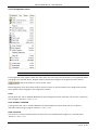
Table Of Contents
1
INTRODUCTION ................................................................................................................................ 1
1.1
2
CONVENTIONS..........................................................................................................................................................................1
RUNNING ITOOLS ............................................................................................................................. 2
2.1
LAUNCHING THE APPLICATION .................................................................................................................................................2
2.2
LOADING DEVICES INTO ITOOLS ..............................................................................................................................................3
2.2.1
2.3
LOADING CLONE DEVICES ........................................................................................................................................................3
2.4
USING THE APPLICATION ..........................................................................................................................................................4
2.4.1
Panel Views ..................................................................................................................................................................4
2.4.2
Device Browser ............................................................................................................................................................5
2.5
Menu Bar ......................................................................................................................................................................6
2.5.2
Main Toolbar...............................................................................................................................................................6
2.5.3
Views Toolbar ..............................................................................................................................................................6
2.5.4
Right Mouse Button ...................................................................................................................................................6
THE PARAMETER EXPLORER WINDOW ................................................................................................................................... 10
3.1.1
Columns ..................................................................................................................................................................... 11
3.1.2
Parameter Explorer tools ....................................................................................................................................... 12
3.1.3
Editing Parameter Values ...................................................................................................................................... 12
3.2
EXPLORER BROWSING AND NAVIGATION .............................................................................................................................. 12
3.2.1
Browse Tool button................................................................................................................................................. 13
3.2.2
Historical navigation .............................................................................................................................................. 13
3.2.3
Vertical navigation.................................................................................................................................................. 14
FLASH MEMORY .............................................................................................................................. 15
4.1
5
WIZARDS ..................................................................................................................................................................................7
PARAMETER EXPLORER ................................................................................................................... 10
3.1
4
NAVIGATION ............................................................................................................................................................................6
2.5.1
2.6
3
Clone devices ...............................................................................................................................................................3
FLASH MEMORY EDITOR ....................................................................................................................................................... 15
4.1.1
Message Table.......................................................................................................................................................... 15
4.1.2
Message Table Config............................................................................................................................................. 17
4.1.3
Promote Parameters ............................................................................................................................................... 17
DEVICE PANEL VIEW........................................................................................................................ 19
5.1
DEVICE PANEL VIEW .............................................................................................................................................................. 19
HA028838
Issue 2 Jly 05
Contents Page i
iTOOLS VERSION 6.20: HELP MANUAL
WATCH/RECIPE ............................................................................................................................... 20
6
6.1
WATCH RECIPE EDITOR.......................................................................................................................................................... 20
6.1.1
7
Creating a Watch List.............................................................................................................................................. 20
GRAPHICAL WIRING EDITOR (GWE)................................................................................................. 22
7.1
INTRODUCTION ...................................................................................................................................................................... 22
7.1.1
Function block type ................................................................................................................................................. 22
7.1.2
Function block instance.......................................................................................................................................... 22
7.1.3
Wire ............................................................................................................................................................................. 23
7.1.4
Block execution order.............................................................................................................................................. 23
7.2
OPENING THE WIRING EDITOR .............................................................................................................................................. 23
7.3
THE GRAPHICAL WIRING EDITOR WINDOW ........................................................................................................................... 24
7.3.1
7.4
8
The Main Window.................................................................................................................................................... 24
CREATING AN APPLICATION ................................................................................................................................................... 26
7.4.1
Using function blocks.............................................................................................................................................. 27
7.4.2
Block Appearance (3500 series and Mini8)........................................................................................................ 28
7.4.3
Block Appearance (Models 2604, 2704) ............................................................................................................. 29
7.4.4
Wiring ......................................................................................................................................................................... 30
7.4.5
Addition of Comments........................................................................................................................................... 32
7.4.6
Addition of Monitor Points .................................................................................................................................... 33
7.4.7
Making selections .................................................................................................................................................... 33
7.4.8
Item Colours .............................................................................................................................................................. 33
FUNCTION BLOCK VIEW.................................................................................................................. 34
8.1
9
FUNCTION BLOCK VIEW ........................................................................................................................................................ 34
TERMINAL WIRING VIEW................................................................................................................. 35
9.1
10
TERMINAL WIRING ................................................................................................................................................................. 35
TOOLKIT BLOCKS VIEW................................................................................................................ 37
10.1
TOOLKIT BLOCKS ................................................................................................................................................................... 37
10.1.1
User Values ................................................................................................................................................................ 37
10.1.2
Analogue operations............................................................................................................................................... 38
10.1.3
Logic Operations ...................................................................................................................................................... 40
10.1.4
Block wiring............................................................................................................................................................... 42
11
ITOOLS WITH THE MODEL 2400.................................................................................................... 43
11.1
PROGRAMMER EDITOR ........................................................................................................................................................... 43
11.1.1
Introduction (2400) ................................................................................................................................................. 43
11.1.2
Program Editing (2400) .......................................................................................................................................... 46
11.1.3
Segment parameters (2400).................................................................................................................................. 47
11.1.4
The Graph (2400) ..................................................................................................................................................... 51
Page ii
HA028838
Issue 2 Jly 05
iTOOLS VERSION 6.20: HELP MANUAL
12
ITOOLS WITH THE MODEL 2704.................................................................................................... 53
12.1
PROGRAMMER EDITOR .......................................................................................................................................................... 53
12.1.1
Introduction (2704)................................................................................................................................................. 53
12.1.2
Opening the editor .................................................................................................................................................. 54
12.1.3
Program editing (2704).......................................................................................................................................... 57
12.1.4
Adding, Inserting and deleting segments .......................................................................................................... 58
12.1.5
Segment parameters (2704) ................................................................................................................................. 60
12.1.6
The Graph (2704)..................................................................................................................................................... 65
12.1.7
Asynchronous Programmer................................................................................................................................... 67
12.1.8
Using the editor in asynchronous mode............................................................................................................. 68
12.2
USER PAGE EDITOR ............................................................................................................................................................... 70
12.2.1
2704 User Page Editor............................................................................................................................................. 70
12.2.2
Promote Parameters ............................................................................................................................................... 73
12.2.3
User List Tab.............................................................................................................................................................. 74
12.2.4
Styles........................................................................................................................................................................... 75
12.2.5
Go to Menu Control Button .................................................................................................................................. 90
13
ITOOLS WITH THE MODEL 3500 SERIES......................................................................................... 91
13.1
DEVICE RECIPE EDITOR .......................................................................................................................................................... 91
13.1.1
13.2
Recipe creation......................................................................................................................................................... 92
PROGRAMMER EDITOR .......................................................................................................................................................... 94
13.2.1
Introduction (3500)................................................................................................................................................. 94
13.2.2
Opening the editor .................................................................................................................................................. 95
13.2.3
Program editing (3500).......................................................................................................................................... 98
13.2.4
Adding, inserting and deleting segments .......................................................................................................... 99
13.2.5
SyncStart segments ............................................................................................................................................... 100
13.2.6
Segment parameters (3500) ............................................................................................................................... 102
13.2.7
The Graph (3500)................................................................................................................................................... 109
13.3
USER PAGE EDITOR .............................................................................................................................................................. 113
13.3.1
Introduction ............................................................................................................................................................ 113
13.3.2
Loop Summary pages ........................................................................................................................................... 116
HA028838
Issue 2 Jly 05
Contents Page iii
iTOOLS VERSION 6.20: HELP MANUAL
THE MENUS ................................................................................................................................117
14
14.1
CONTEXT MENUS .................................................................................................................................................................117
14.1.1
Block Wiring context menu .................................................................................................................................117
14.1.2
Chart context menu (OPC Scope) ......................................................................................................................119
14.1.3
Comment context menu.......................................................................................................................................120
14.1.4
Device context menu .............................................................................................................................................122
14.1.5
Device Recipe Data Sets context menu.............................................................................................................126
14.1.6
Device Recipe parameter context menu ...........................................................................................................127
14.1.7
Diagram context menu.........................................................................................................................................128
14.1.8
Flash Memory Context menu ..............................................................................................................................130
14.1.9
Function Block context menu .............................................................................................................................131
14.1.10
Graph context menu .........................................................................................................................................134
14.1.11
List context menu (OPC Scope) ......................................................................................................................135
14.1.12
Monitor context menu......................................................................................................................................137
14.1.13
User Page Editor Context menu (2704) ........................................................................................................139
14.1.14
Pages context menu..........................................................................................................................................141
14.1.15
Segment context menu (2400) .......................................................................................................................142
14.1.16
Segment context menu (2704) .......................................................................................................................143
14.1.17
Segment context menu (3500) .......................................................................................................................144
14.1.18
Terminal Wiring context menu.......................................................................................................................146
14.1.19
Toolbar context menu ......................................................................................................................................147
14.1.20
Watch Recipe context menu ...........................................................................................................................148
14.1.21
Wire Context menu ...........................................................................................................................................150
14.2
MENU BAR MENUS ...............................................................................................................................................................152
14.2.1
Device menu ............................................................................................................................................................152
14.2.2
Explorer menu.........................................................................................................................................................155
14.2.3
File menu..................................................................................................................................................................157
14.2.4
Flash menu ..............................................................................................................................................................160
14.2.5
Function Block menu ............................................................................................................................................161
14.2.6
Help menu................................................................................................................................................................162
14.2.7
OPC Scope menu....................................................................................................................................................164
14.2.8
Options menu..........................................................................................................................................................170
14.2.9
Pages menu (2704) ................................................................................................................................................178
14.2.10
Pages menu (3500)............................................................................................................................................181
14.2.11
Programmer menu ............................................................................................................................................182
14.2.12
Recipe menu (Device Recipe) ..........................................................................................................................185
14.2.13
Recipe menu (Watch/Recipe)..........................................................................................................................188
14.2.14
View menu...........................................................................................................................................................190
14.2.15
Window menu ....................................................................................................................................................192
14.2.16
Wiring menu .......................................................................................................................................................195
Page iv
HA028838
Issue 2 Jly 05
iTOOLS VERSION 6.20: HELP MANUAL
15
THE TOOLBARS ...........................................................................................................................197
15.1
MAIN TOOLBAR .................................................................................................................................................................. 197
15.2
VIEWS TOOLBAR .................................................................................................................................................................. 200
15.3
DEVICE RECIPE TOOLBAR ..................................................................................................................................................... 202
15.4
FLASH TOOLBAR .................................................................................................................................................................. 203
15.5
OPC SCOPE SERVER TOOLBAR ............................................................................................................................................ 204
15.6
OPC SCOPE TOOLBAR ......................................................................................................................................................... 205
15.7
PROGRAMMER TOOLBAR ..................................................................................................................................................... 207
15.8
TERMINAL WIRING TOOLBAR .............................................................................................................................................. 209
15.9
USER PAGE EDITOR TOOLBAR (2704) ................................................................................................................................ 210
15.10
USER PAGE EDITOR TOOLBAR (3500) ............................................................................................................................ 212
15.11
WATCH/RECIPE TOOLBAR ............................................................................................................................................... 213
15.12
WIRING EDITOR TOOLBAR............................................................................................................................................... 214
16
OPC SCOPE .................................................................................................................................215
16.1
INTRODUCTION ................................................................................................................................................................... 215
16.1.1
Writing New Values............................................................................................................................................... 215
16.1.2
Adding Parameters to the list............................................................................................................................. 216
16.1.3
Removing Parameters from the list ................................................................................................................... 216
16.1.4
List Tab..................................................................................................................................................................... 216
16.1.5
Chart Tab................................................................................................................................................................. 216
16.1.6
Maximize Chart...................................................................................................................................................... 216
16.1.7
History Page Control............................................................................................................................................. 216
16.1.8
OPC Menu items .................................................................................................................................................... 216
16.1.9
OPC Tools ................................................................................................................................................................ 216
16.2
CHART DISPLAY ................................................................................................................................................................... 217
16.2.1
Display parameters ............................................................................................................................................... 217
16.2.2
Chart Configuration.............................................................................................................................................. 218
16.2.3
Review tab ............................................................................................................................................................... 222
16.3
DATA LOGGING (OPC SCOPE) ........................................................................................................................................... 223
16.3.1
Data logging configuration ................................................................................................................................ 223
16.3.2
Log initiation........................................................................................................................................................... 223
16.3.3
Log termination ..................................................................................................................................................... 223
16.3.4
Spreadsheet display............................................................................................................................................... 224
16.4
DDE INTERFACE (OPC SCOPE) .......................................................................................................................................... 225
16.5
GROUP ITEM VALUE WRITES................................................................................................................................................. 227
HA028838
Issue 2 Jly 05
Contents Page v
iTOOLS VERSION 6.20: HELP MANUAL
TCP PORT SETUP.........................................................................................................................228
17
17.1
TCP PORT CONFIGURATION ................................................................................................................................................228
17.1.1
18
TCP/IP Tab ...............................................................................................................................................................230
COMMAND LINE OPTIONS ..........................................................................................................231
18.1
AVAILABLE COMMAND LINE OPTIONS ..................................................................................................................................231
18.1.1
/Addall......................................................................................................................................................................231
18.1.2
/NoPurge..................................................................................................................................................................231
18.1.3
/NoSplash ................................................................................................................................................................231
18.1.4
/NoWarn ..................................................................................................................................................................231
18.1.5
/RegServer ................................................................................................................................................................231
18.1.6
/Scan .........................................................................................................................................................................231
18.1.7
/Server:name or /Server ........................................................................................................................................231
18.1.8
/UnregServer............................................................................................................................................................231
19
ITOOLS ARCHITECTURE...............................................................................................................232
19.1
ITOOLS SHELL ......................................................................................................................................................................232
19.2
ACTIVEX CONTROLS ............................................................................................................................................................232
19.2.1
Series2000Panel......................................................................................................................................................232
19.2.2
OPCItemGrid............................................................................................................................................................233
19.3
OPC SERVER .......................................................................................................................................................................233
19.3.1
20
Instrument Descriptor Modules ..........................................................................................................................233
STAND-ALONE PROGRAM EDITOR ..............................................................................................234
20.1
PROGRAM EDITING WITHIN ITOOLS .....................................................................................................................................234
20.2
PROGRAM EDITING OUTSIDE ITOOLS ...................................................................................................................................234
20.2.1
Opening the Programmer Editor ........................................................................................................................234
20.3
PROGRAMMER EDITOR TOOLBAR ........................................................................................................................................235
20.4
COMMAND LINE OPTIONS....................................................................................................................................................237
20.4.1
/StayOnTop .............................................................................................................................................................237
20.4.2
/ReadOnly ................................................................................................................................................................237
20.4.3
/TabbedOpen ..........................................................................................................................................................237
20.4.4
/Device:<device name>.........................................................................................................................................237
20.4.5
/ProgNum:<number>............................................................................................................................................237
20.4.6
/Quiet:<filename>..................................................................................................................................................237
20.4.7
/LoadFile:<filename> ............................................................................................................................................237
20.4.8
Program Download Example ..............................................................................................................................237
20.5
CONFIGURING THE RUNTIME ENVIRONMENT ......................................................................................................................238
20.5.1
Introduction.............................................................................................................................................................238
20.5.2
Customising New Program Creation .................................................................................................................240
Page vi
HA028838
Issue 2 Jly 05
iTOOLS VERSION 6.20: HELP MANUAL
20.6
MENUS ................................................................................................................................................................................ 243
20.6.1
Device menu............................................................................................................................................................ 243
20.6.2
Edit Menu ................................................................................................................................................................ 244
20.6.3
File menu ................................................................................................................................................................. 247
20.6.4
Help Menu............................................................................................................................................................... 249
20.6.5
Options Menu......................................................................................................................................................... 250
20.6.6
Plot Menu ................................................................................................................................................................ 250
20.6.7
Context menus ....................................................................................................................................................... 251
20.6.8
Chart context menu .............................................................................................................................................. 253
21
OTHER ITEMS..............................................................................................................................254
21.1
REPORT CONFIGURATION .................................................................................................................................................... 254
21.1.1
Report Templates................................................................................................................................................... 254
21.1.2
Save settings as default........................................................................................................................................ 254
21.2
LISTS TAB ............................................................................................................................................................................ 254
21.3
COLUMNS TAB .................................................................................................................................................................... 255
21.4
ANNOTATE TAB................................................................................................................................................................... 255
21.5
FORMAT TAB ....................................................................................................................................................................... 256
22
REVIEW MODE ENTRY.................................................................................................................257
INDEX.......................................................................................................................................................I
HA028838
Issue 2 Jly 05
Contents Page vii
iTOOLS VERSION 6.20: HELP MANUAL
This page is deliberately left blank
Page viii
HA028838
Issue 2 Jly 05
iTOOLS VERSION 6.20: HELP MANUAL
1
Introduction
These help pages apply to iTools version 6.20.
Please note that not all facilities are available to each product supported by iTools. Where a feature is not
available to a product (Graphical Wiring for example), then the toolbar icon, or menu item does not appear.
1.1
Conventions
When instructions are given to use a keyboard key, the key name is displayed thus: <Insert>. The keys' names
may vary from keyboard to keyboard, in particular <Insert> may appear as <Ins>, and <Delete> may appear
as <Del>.
HA028838
Issue 2 Jly 05
Page 1
iTOOLS VERSION 6.20: HELP MANUAL
2
Running iTools
2.1
Launching the Application
iTools may be launched in any of the following ways:
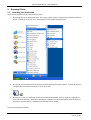
1.
By starting the iTools application itself. The setup program creats a program group called 'Eurotherm
iTools', containing an 'iTools' icon. Selecting this icon launches the application.
2. By opening an instrument clone file directly from the Windows Explorer or Shell. A Clone file may be
recognised by its filename extension (.UIC) or by its icon.
or
3. By opening a view of a connected on-line device from the Eurotherm network explorer (supplied as a
part of Eurotherm Suite). Each device attached to a Modbus port in the Eurotherm Network explorer
presents an 'Open in iTools' command on its file and context menus.
See also Command-line options
Page 2
HA028838
Issue 2 Jly 05
iTOOLS VERSION 6.20: HELP MANUAL
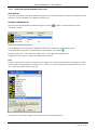
2.2
Loading Devices into iTools
Note: For certain instruments, a 'Wizard' appears when a 'new' instrument is loaded. These
wizards allow device configuration from a sequence of set-up pages. See 'Wizards' for more
details.'
Devices can be loaded into iTools in the following ways:
in the toolbar, or by selecting 'Enable background scan' in the Device menu, or
By clicking on the Scan icon
by using the shortcut <Ctrl> + <Alt> +<S>
By clicking on the 'Add' icon
in the toolbar, or by selecting 'Add...' in the Device Menu, or by using the
shortcut <Alt> + <Insert>, or by right clicking in the Panel views window at the bottom of the iTools window,
then selecting 'Add Devices...' Use of the 'Add' feature displays a dialogue box showing all the devices known to
the Modbus server. See the Options menu description for more details (Options/Advanced/Show server).
By opening a view of a real or clone device in the Eurotherm network explorer. The same copy of iTools can be
used to open all device views.
By dragging a device icon out of the Eurotherm Network explorer and dropping it into the iTools window.
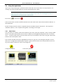
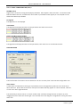
2.2.1
Clone devices
Clone devices can be used to set up a configuration for a particular device type, and then download this
configuration to a real device. It is also possible to read the configuration from a real instrument and transfer it
into a clone device for editing.
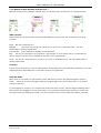
On the screen, clones for devices which incorporate digital displays, can be distinguished from 'real' instruments
by the colour of the digital display - yellow for real instruments and white for clone instruments. Clones for
devices without digital displays are 'filled' grey, whereas real devices are 'filled' green.
See 'Loading Clone Devices' for more details.
2.3
Loading Clone Devices
Clone files may be 'opened' in the following ways:
or, by selecting 'New Clone File...' in the
For new files, by clicking on the 'New File' icon in the toolbar
File menu, or, by right clicking in the Panel views window at the bottom of the iTools window then selecting
'New Clone File...'
or, by selecting 'Open Clone File' in
For existing files, by clicking on the 'Open File' icon in the toolbar
the File menu or, by double clicking on a clone file from Windows explorer or shell or, by dragging a file out of
explorer and dropping it into the iTools window or, by right clicking in the Panel views window at the bottom of
the iTools window, then selecting 'Open Clone File...'.
HA028838
Issue 2 Jly 05
Page 3
iTOOLS VERSION 6.20: HELP MANUAL
2.4
Using the Application
iTools uses a 'device workspace' architecture which allows the user to open views on multiple devices, but
normally,only views associated with the currently selected device are visible.
Note: A device view can be made permanently visible by clicking on the panel-pin icon at the top
right of the view. When 'pinned', the pin changes shape, and has a red background when a
different device is selected as the current device.
Pinout icon =
;
Pinned icon =
There are two device selection windows docked to the main iTools frame: Panel Views and Device Browser, as
described below.
Double clicking on a device name or faceplate launches the default view for that device. This may be the
'Parameter explorer' or the 'Graphical wiring editor' according to device type.
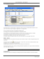
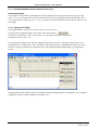
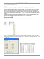
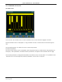
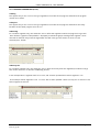
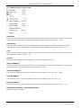
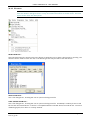
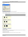
2.4.1
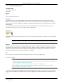
Panel Views
This view, which as a default, resides at the bottom of the frame, shows the 'faceplates' of the currently loaded
devices. The panel views window can be shown or hidden by selecting/deselecting 'Panel Views' in the View
menu. The panel views frame can be set either at the top or the bottom of the frame using the 'Panel Views
Position' item of the Options menu.
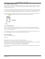
The currently selected instrument is highlighted by means of a grey box surrounding the faceplate. Devices
which are in configuration mode display a 'spanner' symbol; devices which have a communications failure for
any reason display a white cross with a red background.
Configuration symbol
Page 4
Comms Fail symbol
HA028838
Issue 2 Jly 05
iTOOLS VERSION 6.20: HELP MANUAL
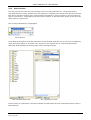
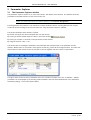
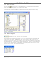
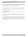
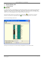
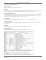
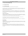
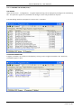
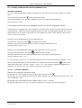
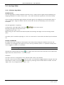
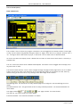
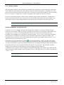
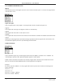
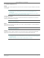
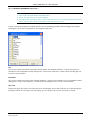
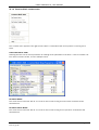
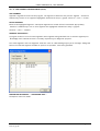
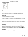
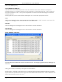
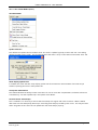
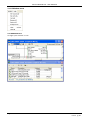
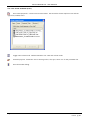
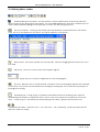
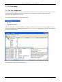
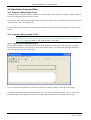
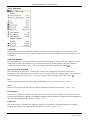
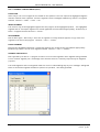
2.4.2
Device Browser
This view, near the top left of the frame, displays a list of currently loaded devices. The OPC parameters
associated with the currently selected device are displayed in a separate pane directly below the device browser.
Each item in the device browser gives communications information for real instruments, or the file location (if
any) for clone devices. Configuration and comms failure symbols, as described above, appear to the left of the
device symbol, if appropriate.
The currently selected device is highlighted.
Device Browser
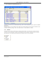
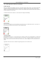
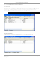
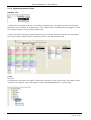
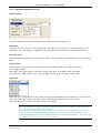
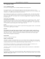
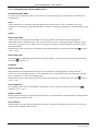
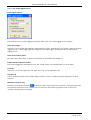
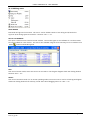
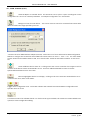
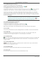
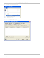
The Find tab at the bottom of the OPC parameter browser window allows the user to search for parameters by
name, description,Address or Comment. The user types in the required item in a field directly below the
'Matching' window (hidden by the drop-down menu in the figure below).
OPC Parameter Browse tab
OPC Parameter Find Tab
Double clicking on a parameter in the OPC Parameter find tab window launches a Parameter Explorer view for
that parameter.
HA028838
Issue 2 Jly 05
Page 5
iTOOLS VERSION 6.20: HELP MANUAL
2.5
Navigation
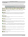
iTools functionality can be accessed by various means, as follows:
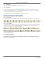
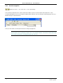
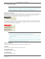
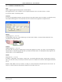
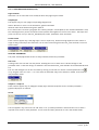
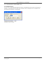
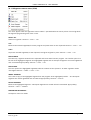
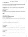
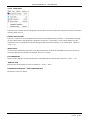
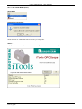
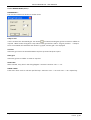
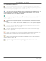
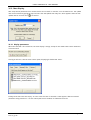
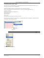
2.5.1
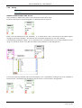
Menu Bar
The iTools Main menu contains a number of items, fully described elsewhere in this document. (See 'The
menus'). The contents of the menu bar varies according to device type. The illustration below is a composite not all device types will display all the menu items shown.
The content of the menu bar items themselves also depends on device type.
2.5.2
Main Toolbar
This toolbar features the functionality of the File and Device menus. See 'The Toolbars' for more information.
2.5.3
Views Toolbar
Located below the main toolbar, this features buttons relevant to the currently selected device type. The toolbar
contents can therefore change according to device type. The displayed view options mimic the entries in the
'Views' menu. See 'The Toolbars' for more information.
As well as launching an instance of the selected view, these buttons also provide a convenient means of bringing
a particular view to the front.
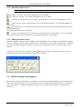
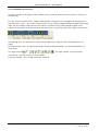
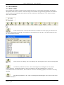
2.5.4
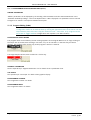
Right Mouse Button
Clicking on the right mouse button, causes a pop-up menu to appear. This menu is relevant to the location of
the tip of the cursor at the time the button is clicked (i.e. it is context sensitive). These menus are therefore
sometimes called 'context menus'.
Page 6
HA028838
Issue 2 Jly 05
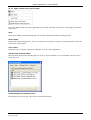
iTOOLS VERSION 6.20: HELP MANUAL
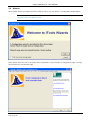
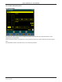
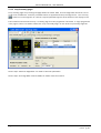
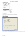
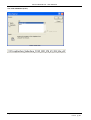
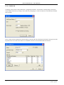
2.6
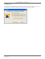
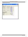
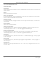
Wizards
When certain devices are loaded into iTools, either as clones or as real devices, a configuration wizard appears.
Note: It is possible to disable this function for Clone files, by 'unchecking' the 'Run Wizard for New
Clone File' item in the Options menu.
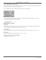
These wizards allow the user to set-up the device's parameters, using a number of configuration pages. Clicking
on the 'Next' key, calls the start page:
HA028838
Issue 2 Jly 05
Page 7
iTOOLS VERSION 6.20: HELP MANUAL
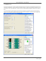
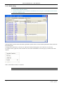
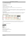
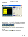
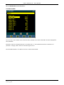
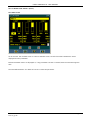
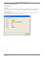
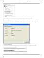
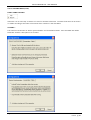
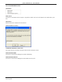
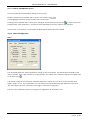
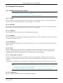
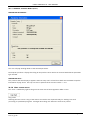
2.6 WIZARDS (Cont.)
As can be seen, there are a number of tabs near the top of the screen, each one representing a specific area of
instrument configuration. These can either be clicked-on directly, or they can be accessed, in sequence, by use
of the 'Next >' key. Once started, the '< Back' key can be used to go back through the sequence one step at a
time.
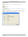
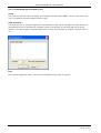
It is not the intention of these pages to describe how to configure an instrument; the 'Input' and 'Summary'
pages for the above wizard are given below to show the style of presentation. As will be seen, the right hand
portion of each window is given over to parameter help.
Page 8
HA028838
Issue 2 Jly 05
iTOOLS VERSION 6.20: HELP MANUAL
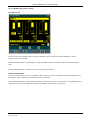
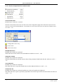
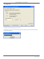
2.6 WIZARDS (Cont.)
Once all the required configuration items have been set up, clicking on the 'Finish' key allows the user to save
the configuration to a clone file, and then to send this clone file to an instrument if required.
HA028838
Issue 2 Jly 05
Page 9
iTOOLS VERSION 6.20: HELP MANUAL
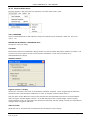
3
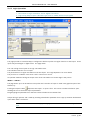
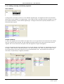
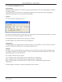
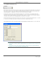
3.1
Parameter Explorer
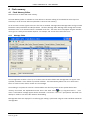
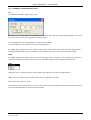
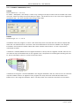
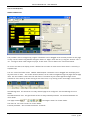
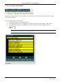
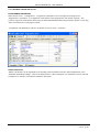
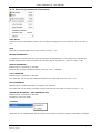
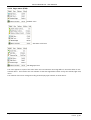
The Parameter Explorer window
The parameter explorer window is, for most instruments*, the default iTools window. The window shows the
parameters associated with the current iTools browse list.
*Note: For some instruments, the default window is the Graphical Wiring Editor
Providing that the first instance is not maximised, multiple window instances, showing different lists, may be
created by double-clicking on the iTools browse tree. Only the active instance is updated.
The window (example shown below) is opened:
By double-clicking on the device faceplate (but see note above),
By clicking on the Parameter Explorer button in the Views Toolbar
By clicking on a folder or subfolder in the parameter browse window
By using the shortcut <Alt> + <X>.
The window opens, showing the parameters associated with the selected folder in the parameter browse
window. Where there are sub-folders, these appear as tabs (e.g. LA and LB in the figure below). The status bar
at the bottom of the window shows the full path of the list, together with the number of parameters.
The figure above shows the three parameters which are considered relevant out of the 13 available. 'Hidden'
parameters can be displayed by de-selecting 'Hide Parameters and Lists when Not Relevant' in the 'Parameter
Availability settings...' item in the Options Menu.
Page 10
HA028838
Issue 2 Jly 05
iTOOLS VERSION 6.20: HELP MANUAL
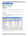
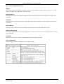
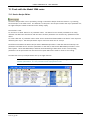
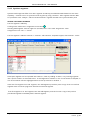
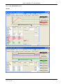
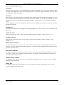
3.1 THE PARAMETER EXPLORER WINDOW (Cont.)
Parameters in blue text are non-editable (Read Only). Items in black text (with the 'pencil' symbol) are editable
(Read/Write)
Parameters with a coloured background are hidden, when 'Hide Parameters and Lists when not relevant' in the
'Parameter Availability settings...' item in the Options Menu is selected (default = hidden)
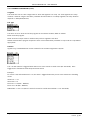
3.1.1
Columns
The figures above show the default display, showing read/write status, name, description, address and value
columns. For some instruments, a further column ('Wired From') also appears. The Explorer menu 'Columns'
item allows the user to define which default and non-default columns are to be displayed.
HA028838
Issue 2 Jly 05
Page 11
iTOOLS VERSION 6.20: HELP MANUAL
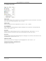
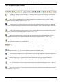
3.1.2
Parameter Explorer tools
Note: Not all of these tools are available for use all of the time.
Back To: List name. See 'Historical Navigation' for more details
Forward to: List name. See 'Historical Navigation' for more details
details.
Up one level. Displays the 'parent' of the currently displayed list. See 'Vertical Navigation' for more
Down one level. Causes a sublist (if any) of the current display to appear. See 'Vertical Navigation' for
more details.
Browse Device lists. Clicking on the down arrow head produces a browse window,allowing a new list to
be selected for display.
See 'Browse Tool button' for more details
Push pin... Clicking on this icon causes the current display to become permanent. I.E it is still viewable
when another device is the current device. See 'Using the application' for more details.
3.1.3
Editing Parameter Values
Writable parameters have their values changed by clicking anywhere in the parameter's row, and either typing a
value in, or making a selection from a pull-down menu. The existence of a pull-down (combo) menu is indicated
by a black downward pointing arrow head. Clicking on this arrow head produces a list of items which may be
selected.
associated with them. Clicking on this button causes a
A number of 'Value cells' have an 'ellipsis' button
dialogue box to be launched which allows time values to be edited.
3.2
Explorer Browsing and Navigation
By default, the browse list displayed in the window is continuously synchronized with the user's browsing activity
in the iTools browse panel tree. This synchronization occurs even when the Parameter Explorer is obscured by
other iTools editors. If multiple Parameter Explorers are open, only the active instance is controlled by the
browse tree.
Page 12
HA028838
Issue 2 Jly 05
iTOOLS VERSION 6.20: HELP MANUAL
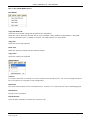
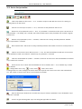
3.2.1
Browse Tool button
calls a browse tree in a drop-down window to appear, an example of which appears
This tool button
below. This allows browsing when the iTools browse window is hidden.
If the iTools browse window is not hidden, it is updated to reflect the newly selected browse list activity.
3.2.2
Historical navigation
(Shortcuts <Ctrl> + <B>, and <Ctrl> + <F> respectively)
The parameter explorer maintains a history buffer of up to 10 lists that have previously been browsed in the
current instance of the window. The 'Back to: List name' and 'Forward to: List name' buttons allow easy
retracing or repeating of the sequence of list selections. Hovering the cursor over either key (if active) causes
the name to be displayed, of the list which will appear if the key is clicked. Clicking on the black down arrow
causes a drop down pick list to appear, which shows the last (up to 10) parameter lists visited in the relevant
direction. The user can then select the required list to go to.
HA028838
Issue 2 Jly 05
Page 13
iTOOLS VERSION 6.20: HELP MANUAL
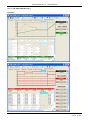
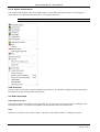
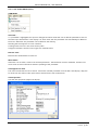
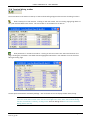
3.2.3
Vertical navigation
(Shortcuts <Ctrl> + <U>, and <Ctrl> + <D> respectively)
The up/down pushbuttons are used to browse the address spaces of devices that have nested lists. If the
currently displayed list has sub-lists then the Down button browses one level deeper, and display these lists as a
tabbed display, as depicted below.
The 'Up' tool button calls the parent of the currently displayed list.
Note: The parameter explorer does not browse to the very top level in the name hierarchy,
because there are no parameters at this level. It is possible, however, to browse to other levels that
do not have parameters, providing that they have sub-lists.
Page 14
HA028838
Issue 2 Jly 05
iTOOLS VERSION 6.20: HELP MANUAL
4
Flash memory
4.1
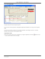
Flash Memory Editor
Not all devices are fitted with flash memory.
The Flash Memory Editor is available to some devices to allow the editing of five tabbed lists that require an
extra step in order to block-write the parameters' values to flash memory.
As can be seen from the figures below, the five lists are entitled: Message Table, Message Table Config, Promote
Parameters, Recipe Definition and Recipe Names. Of these, Message Table, Message Table Config and Promote
Parameters have a user interface which is dedicated to the lists. The other lists are displayed using the standard
iTools grid, as used by the Parameter Explorer, for example, and are not discussed further here.
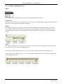
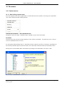
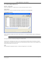
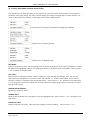
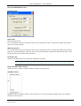
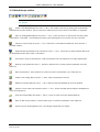
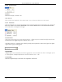
4.1.1
Message Table
The message table contains a list of up to 15 items, each of which defines the message that is to appear if the
specified parameter's value satisfies a specified condition. The Flash Memory Editor tool bar or Flash menu
items are used to insert, delete, reorder etc. the messages.
Once editing is complete, the new list is downloaded to the device by means of the 'Update device flash
or by using the shortcut + . In all
memory' tool button, the 'Update Device Flash' item in the 'Flash' menu,
cases, a confirmation message appears before download is carried out. The user is prompted to download if an
attempt is made to close the editor without downloading.
Message table items are displayed in a read-only grid: editing is performed using the control windows below the
message table.
HA028838
Issue 2 Jly 05
Page 15
iTOOLS VERSION 6.20: HELP MANUAL
4.1.1 MESSAGE TABLE (Cont.)
PARAMETER
There are a number of ways to access parameters for editing:
Invoke a browse dialogue by clicking on the ellipsis button adjacent to the parameter entry field.
Invoke a browse dialogue by double-clicking on the grid row
Invoke a browse dialogue by attempting to type into the Parameter entry field.
Drag parameters onto any grid row from elsewhere in iTools
Invoke a browse dialogue using the 'Edit Parameter' tool button, Flash menu or Context menu item
Invoke a browse dialogue using the shortcut <Ctrl> + <E>
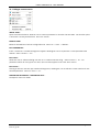
CONDITION
This allows the message display condition to be defined from a drop-down pick lists.
Note: the figure below is a composite image. The two pick lists cannot be displayed
simultaneously.
Operator
=
Message displayed if the parameter value is equal to the entered Value
<>
Message displayed if the parameter value is not equal to the entered Value
>
Message displayed if the parameter value is greater than the entered Value
<
Message displayed if the parameter value is less than the entered Value
Mask
Message displayed if all the bits in the parameter match all the bits in the entered value
Value
Allows the user to enter a value against which the parameter value is to be compared.
Priority
Allows the user to set the message priority as 'Low', 'Medium' or 'High'. These priority levels define the gap
between message displays.
These time delays are individually configurable in Message Table Config, below.
MESSAGE
This text-entry field allows the user to enter the message to be displayed when the Condition criterion is met.
Page 16
HA028838
Issue 2 Jly 05
iTOOLS VERSION 6.20: HELP MANUAL
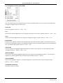
4.1.2
Message Table Config
This window allows the user to set up time constants associated with message displays (see 'Message Table'
above). All values are in units of 100msec., thus an entry of 30 equates to a gap of 3 seconds.
SPEED
The speed at which message characters move across the display. The default speed is 400 milliseconds between
character 'jumps'.
PRIORITY DELAYS
These priority delays define the gap between the final character of a message's disappearance, and the
subsequent reappearance of the first character of the same message. Several messages with the same priority
level may be grouped together into one big message.
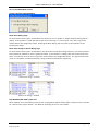
4.1.3
Promote Parameters
The parameter promotion table contains a list of up to 60 items. The purpose of the list is to arrange the listed
parameters in a specific order for display by the device. Parameters can be added, deleted, moved etc. by means
of the Flash Memory Editor toolbar, or by the 'Flash' menu.
HA028838
Issue 2 Jly 05
Page 17
iTOOLS VERSION 6.20: HELP MANUAL
4.1.3 PROMOTE PARAMETERS (Cont.)
Once editing is complete, the new list is downloaded to the device by means of the 'Update device flash
or by using the shortcut + . In any case, a
memory' tool, the 'Update Device Flash' item in the 'Flash' menu,
confirmation message appears before download is carried out. The user is prompted to download if an attempt
is made to close the editor without downloading.
The parameter promotion table items are displayed in a read-only grid: editing is performed using the control
windows below the message table.
PARAMETER
There are a number of ways to access parameters for editing:
Invoke a browse dialogue by clicking on the ellipsis button adjacent to the parameter entry field.
Invoke a browse dialogue by double-clicking on the grid row
Invoke a browse dialogue by attempting to type into the Parameter entry field.
Drag parameters onto any grid row from elsewhere in iTools
Invoke a browse dialogue using the 'Edit Parameter' tool button, Flash menu or Context menu item
Invoke a browse dialogue using the shortcut <Ctrl< + <E>
LEVEL
Allows 'Level 2', or 'Level 1 + 2' to be selected from a drop-down pick list.
Levels 1 and 2 relate to Operator Access Levels as discussed in the relevant User Manual.
ACCESS
Allows the user to set the parameter access as Read Only or Read Write
Page 18
HA028838
Issue 2 Jly 05
iTOOLS VERSION 6.20: HELP MANUAL
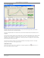
5
5.1
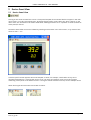
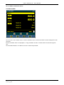
Device Panel View
Device Panel View
Clicking on this Views Toolbar item causes a front panel faceplate of the selected device to appear in the main
iTools frame. For many instruments types, any digital displays and/or push buttons etc. which 'appear' on the
device itself, are mimicked on this Device Panel View, allowing the device to be 'operated' via iTools (instead of
at the panel) if desired.
The Device Panel View can also be initiated by selecting 'Device Panel' in the 'View' menu, or by means of the
shortcut <Alt> + <E>.
A device-specific toolbar appears above the faceplate, to allow, for example, combinations of keys to be
operated simultaneously. Hovering the mouse cursor over these tool buttons causes a tool tip to appear,
containing a description of the button function. The figures below show these tool tips for the example above.
Other device types will have other tool button functions.
HA028838
Issue 2 Jly 05
Page 19
iTOOLS VERSION 6.20: HELP MANUAL
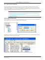
6
Watch/Recipe
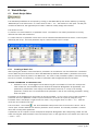
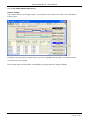
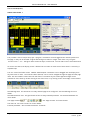
6.1
Watch Recipe Editor
The watch/Recipe Window can be opened by clicking on the Watch/Recipe tool button (above), by selecting
'Watch/Recipe' in the Views menu, or via the shortcut <Alt> + <A>. The window is in two parts: the left part
contains the watch list; the right-hand part contains a data set, initially empty and unnamed.
The window is used:
To monitor a so-called 'watch list' of parameter values. The watch list can contain parameters from many
different lists within the same device.
To create 'data sets' of parameter values which can be selected and downloaded to the device, in the sequence
defined by the recipe. The same parameter may be used more than once in a recipe.
6.1.1
Creating a Watch List
After opening the window, as described above, parameters can be added to it as described below. Parameters
can be added only from the device to which the Watch/Recipe window relates (that is, parameters from more
than one device cannot be placed in one Watch list). The values of the parameters update in real time, allowing
the user to monitor, simultaneously, a number of parameters which might otherwise be unrelated.
ADDING PARAMETERS TO THE WATCH LIST
1.
Parameters can be 'click-dragged' into the watch list grid from elsewhere in iTools (for example: the
main browse tree, the Parameter Explorer window, the Graphical Wiring Editor (if applicable)). The
parameter is placed either in the empty row at the bottom of the list, or 'on top' of an existing
parameter, in which case it is inserted above this parameter in the list, the remaining parameters moving
down one place.
Parameters can be dragged from one position in the list to another. In such a case, a copy of the parameter is
produced: the source parameter remains in place. Parameters can be also be copied by using the 'Copy
Parameter' item in the Recipe or right mouse-click menu, or by using the short cut <Ctrl> + <C>. Data set
values are not included in the copy.
, the 'Insert Parameter' Recipe menu item or the shortcut <Insert> can be
The 'Insert item...' tool button
used to open a browse window from which a parameter can be selected. The selected parameter is inserted
above the currently active parameter.
A parameter can be 'copied' from (for example) the Graphical Wiring Editor and subsequently 'pasted' into the
watch list using the 'Paste Parameter' item in the Recipe menu, or the right mouse-click context menu (short cut
= <Ctrl> + <V>).
Page 20
HA028838
Issue 2 Jly 05
iTOOLS VERSION 6.20: HELP MANUAL
CREATING A DATA SET
All the parameters required for the recipe should be added to the watch list, described above.
Once this has been done, if the empty data set is selected (by clicking on the column header), the 'Snapshot'
tool button
can be used to fill the data set with the current values. Alternatively, the 'Snapshot Values'
item in the Recipe or context (right click) menu or the shortcut <Ctrl> + <A> can be used to fill the data set.
Individual data values can now be edited by typing directly into the grid cells. Data values can be left blank or
cleared, in which case, when the recipe is downloaded, no value will be written for those values. Data values can
be cleared by deleting all the characters in the field, then, either moving to a new cell, or typing <Enter>.
The set is called 'Set 1' by default. The name can be edited by using the 'Rename Data Set...' item in the Recipe
or right mouse-click menu, or by using the shortcut <Ctrl> + <R>.
New data sets can be added and edited in the same way, by using the 'Create a new empty....' tool button
or by selecting the 'New Data Set' item in the Recipe or right mouse-click menu, or by using the shortcut +
,
Once all the data sets required for the Recipe have been created, and saved, they can be downloaded to the
device, one at a time, using the download tool
<Ctrl> + <D>.
, or equivalent Recipe/context menu item, or the shortcut
For descriptions of other tool buttons, see 'Watch/Recipe toolbar'. For descriptions of Recipe menu items, see
'Recipe Menu (Watch/Recipe)'.
HA028838
Issue 2 Jly 05
Page 21
iTOOLS VERSION 6.20: HELP MANUAL
7
Graphical Wiring Editor (GWE)
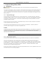
7.1
Introduction
This View menu button appears only for instruments which support graphical wiring.
The Graphical wiring editor is used to view and/or edit instrument block wiring (not physical signal cabling etc.).
Comments may be added and monitor windows can be linked to inputs and outputs, to show instantaneous
values. The remainder of this introduction takes the form of a glossary, describing the terminology used in the
topic as a whole.
7.1.1
Function block type
The wiring editor groups parameters into one or more function blocks. A 'function block type' defines the
parameters needed to make up a unit of instrument functionality. Control loops and mathematical calculations
are examples of function block types. In most cases, a function block type is all the parameters in an iTools
parameter list (and its sublists).
Function blocks have inputs and outputs. Any parameter may be used as an output, but there are restrictions
on which parameters may be used as inputs.
The function block type definition does not refer to a specific set of parameters: it defines a pattern of
parameters (which may appear in more than one parameter list).
EXAMPLE
A simple block type may be called 'Add', and may contain three parameters, 'In1', 'In2' and 'Out'. The purpose
of the block is to add 'In1' to 'In2', and place the result in 'Out'. Thus, although the block type definition
includes the name of the block and the names of the parameters, it does not know where the parameters reside
within the device's address space.
Note: The Function block types available to the Graphical Wiring Editor vary from device to device.
7.1.2
Function block instance
A function block instance takes a function block type definition and maps it to a specific set of parameters.
In the case of the Add block in the example above, an instance (Add.1) would contain the OPC path to a
parameter list which contains all the parameters in the Add block. For a Mini8 or 350x, the parameters would
be called 'Add.1.In1', 'Add.1.In2' and Add.1.Out. If a further instance of the Add block were to be introduced,
this would be called Add.2, and its parameters would be 'Add.2.In1', 'Add.2.In2' and Add.2.Out. Other
instruments may use a different naming structure
Function block instances remember their input and output parameter values, so once a parameter value is set, it
will retain that value until something changes it.
Page 22
HA028838
Issue 2 Jly 05
iTOOLS VERSION 6.20: HELP MANUAL
7.1.3
Wire
A wire transfers a value from one parameter to another. Transfers are executed by the device once per control
cycle.
Wires are created from the output of a function block to the input of a function block. It is possible to create a
wiring loop, in which case there will be a single iteration delay at some point in the loop. For a Mini8 or 350x,
this point is shown on the diagram, and it is possible to move this position if required, and thus to choose where
the delay will occur.
7.1.4
Block execution order
For Mini8 and model 350x only, the order in which blocks are executed by the device depends on the way in
which they are wired. If there are no loops, they will be ordered such that each block output has been set by
the block execution before its value is transferred to another block. Block execution order appears in the
bottom left corner of each block.
The execution order for models 2400 and 2704 is fixed, and not shown on the diagram
7.2
Opening the Wiring Editor
For those instruments that support the feature, the graphical wiring editor can be opened by:
Double clicking on the device faceplate in the Panel Views area.
Clicking on the Graphical Wiring Editor button (shown above) in the Views toolbar.
Selecting 'Graphical wiring' from within the 'Views' menu.
By right clicking on the device faceplate, and selecting 'Graphical Wiring' from the resulting context menu.
The Graphical wiring tool button can also be used to bring the existing wiring diagram to view if it is obscured
by other windows.
HA028838
Issue 2 Jly 05
Page 23
iTOOLS VERSION 6.20: HELP MANUAL
7.3
The Graphical Wiring Editor window
The Graphical Wiring Editor window is in two parts, called 'the tree view' and 'the main window'. Note that
block and parameter names vary from device to device.
7.3.1
The Main Window
This consists of the main drawing area and the toolbar. The main drawing area contains the wiring diagram. See
'Creating an Application' for an example.
NAVIGATION
The visible part of the diagram can be moved within the window in the following ways:
By using the up, down, left and right keyboard keys.
By using the horizontal and vertical scroll bars
In select mode
In Pan mode
, by holding down the shift key, then click-dragging on the diagram.
, by click-dragging on the diagram.
By using the Pan tool
.
See 'Wiring editor toolbar' for details of these and other tools.
Page 24
HA028838
Issue 2 Jly 05
iTOOLS VERSION 6.20: HELP MANUAL
7.3.1 THE MAIN WINDOW (Cont.)
THE TREE VIEW
This window contains:
Comment
Monitor
IO
A list of function block types
Comment
To add a comment to the wiring diagram, click/drag the Comment item from the Tree View to the Main
Window. A text entry box appears to allow the user to enter the comment text, followed by 'OK'. The text
entry box closes, and the comment box appears in the wiring diagram at the point at which the mouse button
was released.
To link the comment to another item, hover the mouse pointer over the bottom right-hand corner of the
comment box, then click on the 'link' symbol which appears there.
Release the mouse button, and move the mouse cursor to the point to which the comment is to be linked, and
click again.
Note: For some devices, new items are drawn with 'dashed' outlines until the file has been downloaded to the device. For all devices, the Link Line is dashed both before and after downloading.
Monitor
Monitor windows are added to the wiring diagram using the same method as described above for Comments
(except that the monitor points do not have a text entry window). Monitor windows are linked to the input or
output of a function. Once the link is established, the displayed value changes from its initial ???????? to the
current value of the input or output point (e.g. PV = 1243.09).
IO
IO shows all the IO function block types and the instances in use in the wiring diagram.
Function block types
Notes
1. Where there is only one available instance of a function block type (Instrument for example)
the tree cannot be expanded at this point.
2. If a function block is in use on the diagram it is 'faded' in the tree view.
3. If all available instances of a block have been used, the block type also becomes faded.
4. Block names vary from device to device.
To enable a block and make it available for wiring, click-drag either the type, or an instance of it, from the tree
to the required position on the diagram. (If the type is dragged, the first available instance of that type will be
used.)
HA028838
Issue 2 Jly 05
Page 25
iTOOLS VERSION 6.20: HELP MANUAL
7.3.1 FUNCTION BLOCK TYPES (Cont.)
Once the block appears on the diagram, a context menu becomes available in the tree window, allowing the
user to open the iTools Function block view for all the parameters in that block. Function block view can be
opened by double clicking on the block, either in the tree or in the diagram, or by clicking the right-hand mouse
button over the block, and selecting Function Block View from the resulting menu.
If the active iTools window is not maximised, multiple function block views can be open at the same time.
If a block instance is clicked on in the tree view, the block is selected and the diagram moves to bring it to the
centre of the view. Clicking on a block also updates the contents of the Function Block View to show the
parameters in the newly selected block.
7.4
Creating an application
When the wiring editor is opened on a connected instrument, the current wiring and diagram layout is read
from the instrument.
For models 2604/2704, any changes made in the diagram are downloaded immediately to the instrument. For
such devices, new items (e.g. blocks, wires) are drawn with solid outlines. The 'download' key writes the wiring
layout to a file on the pc.
For series 3500 devices and Mini8, changes made in the diagram have no effect on the block execution or wiring
of the actual instrument until the download key is pressed, at which time, the wiring diagram is written to the
instrument. For such devices, new blocks, wires etc. are drawn with green, dashed outlines, and deleted items
are drawn 'ghosted' and dashed, (and can be 'undeleted'), until the download button is operated. If changes
are made, and the editor is subsequently closed without those changes being saved, a delay will occur whilst the
editor clears the changes.
Page 26
HA028838
Issue 2 Jly 05
iTOOLS VERSION 6.20: HELP MANUAL
7.4.1
Using function blocks
INTRODUCTION
If a function block is not 'faded' in the tree, then it can be dragged into the diagram. Once in the diagram, it
can be moved by click-dragging with the mouse, or the selected item can be moved using the keyboard left,
right, up and down keys. Blocks can be deleted using the right mouse-click 'context' menu or by operating the
<Delete> key.
A block labelled 'Loop' is depicted below, where 'Loop' is the name of the block instance.
Hovering the mouse cursor over the block, causes 'tooltips' to appear. In the figure below the tooltip for 'Main
PV' is shown as an example.
If the Block Type information is editable, clicking on the adjacent down arrow, causes a pop-up window to
appear, allowing the user to select or enter a new value:
The inputs and outputs which are commonly of most use appear within the body of the block. Further
parameters can be selected by clicking on the 'Select Output' icon at the bottom right of the block.
Generally, for blocks to be of use, parameters must be 'wired' to other parameters. To start a wire from a
recommended output, click on the output parameter, then move the mouse cursor to the destination point, and
click again on the required input.
HA028838
Issue 2 Jly 05
Page 27
iTOOLS VERSION 6.20: HELP MANUAL
7.4.2
Block Appearance (3500 series and Mini8)
DASHED OUTLINE
When first dragged into the diagram, the block is shown with a green, dashed outline. This shows that the block
is enabled, but is not yet being executed by the instrument. The block remains in this state, until the wiring
diagram is downloaded into the instrument. The block is then added to the instrument function block execution
list and is drawn with a solid outline.
If a dashed outline block is deleted, it is removed from the diagram immediately.
SOLID OUTLINE
When the wiring diagram has been downloaded, any dashed items are re-drawn with solid lines. The block is in
the instrument's function block execution list, and is being executed.
GHOSTED OUTLINE
Not applicable to all devices. If a solid outline block is deleted, it remains on the wiring diagram in a dashed and
ghosted form, to show that it is still being executed by the instrument. The ghosted image is removed from the
diagram, and from the instrument function block execution list, after the diagram has been downloaded to the
device.
A ghosted outline block can be 'undeleted' using the right mouse-click 'context' menu.
Page 28
HA028838
Issue 2 Jly 05
iTOOLS VERSION 6.20: HELP MANUAL
7.4.3
Block Appearance (Models 2604, 2704)
New items are downloaded to the instrument immediately. There are no dashed or ghosted states as described
above, for the Series 3500 and Mini8 devices.
If an item is deleted, it is immediately removed from the diagram. The 'Undo' tool button must be used to
restore it. This button 'undoes' item-by-item back to the time the Wiring editor was last opened.
New blocks, wires, monitor windows appear as shown below.
HA028838
Issue 2 Jly 05
Page 29
iTOOLS VERSION 6.20: HELP MANUAL
7.4.4
Wiring
Note: New blocks, wires etc. may be drawn green and dashed (as shown) or solid, according to
device type.
MAKING A WIRE BETWEEN TWO BLOCKS
In this example, a maths block output is to be wired to an alarm block input.
Locate the two blocks to be wired together, or add new blocks as required.
Either click on the Maths block 'Out' parameter, or, as shown below, click on the wiring icon at bottom right to
display the Connection dialogue. This shows all the connectable parameters for the block, with the
recommended parameters in green. (If it is required to wire a parameter that is not currently available, the red
'plug' icon should be clicked on to add non-wirable (red) parameters to the dialogue box.)
Click on the required parameter ('Out' for this example). This is equivalent to clicking on the 'Out' parameter in
the block view. The dialogue box disappears, and the mouse cursor becomes a wiring pointer.
Page 30
HA028838
Issue 2 Jly 05
iTOOLS VERSION 6.20: HELP MANUAL
7.4.4 MAKING A WIRE BETWEEN BLOCKS (Cont.)
Move this pointer to the parameter labelled 'Input' in the Alarm block, and left click to complete the wire.
WIRE COLOURS
Dashed wires (not all devices) have not been downloaded to the instrument, and are therefore not being
executed.
Black:
Normal, functioning wire.
Magenta:
The mouse is hovering over a black wire or its source or destination block. This aids
identification in densely packed wires.
Grey, dashed:
A wire marked for deletion at next download
Red:
The wire is connected to an input which is not alterable, or to an output which is not available for
wiring. Values on the wire will be rejected by the input, or be indeterminate.
Violet: The mouse is hovering over a red wire or its source or destination block. This aids identification in
densely packed wires.
TOOLTIPS
If the mouse is hovered over a wire, a tooltip appears, showing the source and destination parameters, and if the
diagram has been downloaded, the current value of the source parameter.
ROUTING WIRES
When a wire is first made, it is autorouted by iTools, which tries to find a clear path amongst the function
blocks. A wire can be autorouted again, either by using the right mouse-click context menu, or by double
clicking on the wire.
If a wire segment is clicked-on, it is redrawn with small boxes at the corners, and each segment between these
boxes can be click-dragged to re-route it manually. iTools remembers that the wire has been re-routed, and
should the block subsequently be moved, as much as possible of the current shape of the path is preserved.
HA028838
Issue 2 Jly 05
Page 31
iTOOLS VERSION 6.20: HELP MANUAL
7.4.4 MAKING A WIRE BETWEEN BLOCKS (Cont.)
USING TAGS
If blocks are some distance apart, or the wires are densely packed, it may be more useful to convert a wire to
source and destination tags as shown below. This is done by right clicking on the wire, and enabling the 'Use
Tags' menu selection. Once created, tags can be moved by click-dragging them to the desired position. The wire
can subsequently be restored by disabling 'Use Tags'.
As shown in the example below, the tags are labelled with their destination block names. As with normal wires,
current values can be viewed by using the tooltip which appears when the cursor hovers over the tag.
7.4.5
Addition of Comments
To add a comment to the wiring diagram, click/drag the Comment item from the Tree View to the Main
Window. A text entry box appears allowing the user to enter the comment text, followed by 'OK'. The text
entry box closes, and the comment box appears in the wiring diagram at the point at which the mouse button
was released.
Note: The text appears in the note box as it appears in the text entry box. Carriage returns are
used if the width of the comment box is to be limited.
To link the comment to a block, wire etc. hover the mouse pointer over the bottom right-hand corner of the
comment box, then click on the chain symbol which appears there. If a wire is selected as the link destination,
the comment box is linked to the centre of the wire.
Release the mouse button, and move the mouse cursor to the point to which the comment is to be linked, and
click again.
Note: For relevant devices the comment box remains green and dashed until the file has been
downloaded to the device. For all instruments, the Link Line remains dashed.
Page 32
HA028838
Issue 2 Jly 05
iTOOLS VERSION 6.20: HELP MANUAL
7.4.6
Addition of Monitor Points
Monitor windows are added to the wiring diagram using the same method as described above for Comments
(except that the monitor points do not have a text entry window). Monitor windows are linked to the input or
output of a function or a wire.
Once the link is established, the displayed value changes from its initial ???????? to the current value of the input
or output point (e.g. PV = 1243.09). If the parameter name is not required, it can be removed by right-clicking
on the link symbol, and disabling 'Show Names'. Show Names can subsequently be re-enabled if required.
It is possible to link a monitor window to any of the block's parameters, by clicking on the link symbol, then on
and selecting a parameter (In2Mul in the example below) from the list.
the 'Chip' icon
7.4.7
Making selections
Selections are made by clicking on the relevant item. Selected wires are shown with small blocks at their
corners; all other items are surrounded with a dashed line when selected. Selecting a block automatically also
selects any wires associated with it.
To select more than one item, < Ctrl> should be operated when the required items are clicked, or the mouse
can be click-dragged to encompass all the required items, and then released.
7.4.8
Item Colours
Items are normally drawn in black
Exceptions:
Red, magenta and violet wires, as described in 'Wire Colours' above.
Items which obscure, or which are partially obscured by other items are drawn in red.
Parameters in function blocks are in black if they are Read/Write, or blue if they are Read Only. If a parameter
in a function block is unavailable, the parameter name has a grey background.
When the mouse is over a parameter, the parameter text turns magenta.
Function blocks, comments and monitors which are not drawn in red, turn magenta when the mouse pointer
hovers over them.
HA028838
Issue 2 Jly 05
Page 33
iTOOLS VERSION 6.20: HELP MANUAL
8
8.1
Function Block View
Function Block View
This view is available only with devices that support the Graphical Wiring Editor or Terminal Wiring view.
The function block view is a variant of the Parameter Explorer that can be created by double clicking on a block
in the
in the Graphical Wiring Editor, or by using the 'View parameters in selected I/O module' tool button
Terminal Wiring view. Multiple copies of the window can be opened, provided that the top iTools window is
not maximised.
Closing the Graphical Wiring Editor (or Terminal Wiring View) also closes all Function Block Views that were
opened from within it.
The list or set of tabbed sublists displayed in the window may be updated by clicking on any of the blocks in the
wiring diagram, or by selecting these used blocks via the Block's browse tree. The function block view has no
explorer-type capabilities.
The function block view has the same context menu as the Parameter Explorer.
Page 34
HA028838
Issue 2 Jly 05
iTOOLS VERSION 6.20: HELP MANUAL
9
9.1
Terminal Wiring view
Terminal Wiring
For certain instruments, a 'Terminal Wiring' tool button (above) allows the user to view the rear terminal panel
of the device, and to determine the hardware setup. The initial view shows the rear panel, with Module One
highlighted. Clicking on other areas of the diagram highlights other modules (module two in the figure below).
Details of the currently highlighted module are given below the terminal layout.
The two tool buttons allow the user to display a list of fitted modules
parameters associated with the highlighted module
(not all devices) or to view the
. See 'Terminal Wiring toolbar' for more details.
See also 'Terminal Wiring context menu'.
Clicking on the Summary tab calls a further display, showing details of all the modules fitted.
HA028838
Issue 2 Jly 05
Page 35
iTOOLS VERSION 6.20: HELP MANUAL
9 TERMINAL WIRING VIEW (Cont.)
Page 36
HA028838
Issue 2 Jly 05
iTOOLS VERSION 6.20: HELP MANUAL
10 Toolkit Blocks View
10.1 Toolkit Blocks
Opened by the Toolkit Blocks Views toolbar tool, by the Toolkit Blocks View menu item or via the context menu
which appears when the selected device faceplate (in Panel Views) is right-clicked. Toolkit blocks simplifies
production of applications by allowing wiring links to be made by 'dragging and dropping' parameters.
Note: The displays vary from device to device
The window has three or, as shown below, four tabs viz: User Values, Analog operations, Logic operations, Block
Wiring. The Block Wiring tab can be enabled or disabled for view using the 'Toolkit Blocks Performance' item in
the Options menu.
10.1.1 User Values
User values are intended for use as constants or comms inputs to calculations.
In the example above, the user value to be edited is selected by clicking on the down arrow and selecting the
required User_Value. For other instruments, only the value can be edited and the page contains a list of all the
supported UserVals.
Items are edited either by clicking on the value or comment area and typing in the required value, or selecting
the required entry from a picklist displayed by clicking on the down arrow at the right-hand end of the relevant
field.
HA028838
Issue 2 Jly 05
Page 37
iTOOLS VERSION 6.20: HELP MANUAL
10.1.2 Analogue operations
Note Also known as 'Analogue calculations'.
This page provides a convenient way to configure the device to perform a mathematical calculation on two
inputs. These inputs may be analogue or digital values. The page allows:
The 'soft' wiring of two inputs to an analogue calculation block.
The ranging of such inputs by the application of a multiplication factor.
The performance of a mathematical calculation on the two inputs. See 'Maths operations' for details
The application of maximum and minimum limits on the result of the calculation.
The provision of a 'fallback' value to be used in case an error occurs.
An optional method of wiring the output value of the calculation to a further stage in the process.
INPUT 1 / INPUT 2
The page allows up to 32 calculations to be performed. Selection of inputs is made in the graphical part of the
window by:
adjacent to the Input 1 or Input 2 field. This causes a browser window to open,
Pressing the ellipsis button
allowing the user to select the required parameter.
Drag-dropping the parameter from the tree browser window to the relevant field.
Output wiring is optional, and is made by selecting a destination parameter from a pop-up browser window that
opens when 'Add' is clicked-on.
Note: The calculations are called An_1 to An_32, or AOPR01 to AOPR32 according to device type.
PARAMETER LIST
Clicking on this button calls a display box showing the input and output parameters used in this calculation.
Page 38
HA028838
Issue 2 Jly 05
iTOOLS VERSION 6.20: HELP MANUAL
10.1.3 ANALOGUE OPERATIONS (Cont.)
HI LIMIT / LO LIMIT
Allows the user to specify a maximum output range.
FALLBACK
Allows the user to enter a value which the output will adopt if an error condition occurs in the calculation. This
value must lie within the Hi and Lo limits, unless Fallback Overrides Limits is enabled (below).
FALLBACK OVERRIDES LIMITS
If 'Fallback Overrides Limits' is enabled, then if the relevant parameter goes invalid for any reason, the fallback
value is adopted whether the fallback value be inside or outside the value's normal clipping limits. If 'Fallback
Overrides Limits' is not enabled, the value will be 'clipped' as normal.
ADD / REMOVE
Allows the user to add (via a browse window) or delete wires from the calculation block output.
FORCE GOOD STATUS
This tickbox appears only for some device types. This is used to force the status of the output to 'Good', even in
error conditions.
COMMENT
Allows a comment to be entered to be associated with this analogue operation.
MATHS OPERATORS
The following mathematical operators are available for each analogue operation.
HA028838
Issue 2 Jly 05
Page 39
iTOOLS VERSION 6.20: HELP MANUAL
10.1.3 Logic Operations
Notes:
1. Also known as 'Logic calculations' and as 'Digital Calculations'.
2. Logic wiring always outputs a 'Boolean' type result no matter what the input type(s)
This page provides a convenient way to configure the device to perform a logical function on two inputs. These
inputs may be analogue or digital values. The page allows:
The 'soft' wiring of two inputs to an logic calculation block.
The individual inversion of such inputs.
The performance of a logical calculation on the two inputs. See 'Logic Operators' for more details.
The provision of a 'fallback' value to be used in case an error occurs.
An optional method of wiring the output value of the calculation to a further stage in the process.
INPUT 1 / INPUT 2
The page allows up to 32 calculations to be performed. Selection of inputs is made in the graphical part of the
window, by:
adjacent to the Input 1 or Input 2 field. This causes a browser window to open,
Pressing the ellipsis button
allowing the user to select the required parameter.
Drag-dropping the parameter from the tree browser window to the relevant field.
Output wiring is optional, and is made by selecting a destination parameter from a pop-up browser window that
opens when 'Add' is clicked-on.
Note: The calculations are called Logic_1 to Logic_32, or DOPR01 to DOPR32 according to device
type.
Page 40
HA028838
Issue 2 Jly 05
iTOOLS VERSION 6.20: HELP MANUAL
10.1.3 LOGIC OPERATIONS (Cont.)
INVERT
Allows each input to be inverted as required. The box is not available for logic functions such as = or >, which
require a numeric entry rather than a 'Boolean' entry.
PARAMETER LIST
Clicking on this button calls a Parameter Explorer view showing the input and output parameters used in this
calculation.
FALLBACK
Allows the user to select a value (True or False) which the output will adopt if an error condition occurs in the
calculation.
ADD / REMOVE
Allows the user to add (via a browse window) or delete wires from the calculation block output.
FORCE GOOD STATUS
This tickbox appears only for some device types. This is used to force the status of the output to 'Good', even in
error conditions.
COMMENT
Allows a comment to be entered to be associated with this analogue operation.
LOGIC OPERATORS
The following operators are available for each logic operation.
HA028838
Issue 2 Jly 05
Page 41
iTOOLS VERSION 6.20: HELP MANUAL
10.1.4 Block wiring
Notes:
1. Also known as ‘Wirable Params’.
2. The Block wiring tab can be enabled or disabled for view, using the ‘Toolkit Blocks Performance’
item in the Options menu.
Wiring between control blocks and other application specific blocks uses the wirable parameters listed under the
Block Wiring tab.
Clicking in the 'Wired From' column calls a Browser window allowing the user to edit the current entry.
To remove a wire, right click in the relevant row, and select 'Delete Wire' from the pop-up context menu that
appears.
After confirmation, the wire is removed.
Note: Wires can also be deleted using the Edit Wire... selection.
Page 42
HA028838
Issue 2 Jly 05
iTOOLS VERSION 6.20: HELP MANUAL
11 iTools with the Model 2400
11.1 Programmer Editor
11.1.1 Introduction (2400)
This sequence of help pages refers to the Model 2400 controller/programmer.
The Programmer Editor is used to edit setpoint programs for those devices which include a programmer. These
pages are not intended to describe the device programmer itself, as this is explained in the user guide and / or
engineering manual appropriate to the device.
Most operations require that the clone or instrument be in 'Configuration' mode. This mode can be entered
either by clicking the right-hand button of the mouse over the required device panel view, then using the 'Set
Access Level...' menu item, or by using the 'Access' tool button to toggle between 'Configuration' and 'Operator'
(see 'Main toolbar').
ONLINE / OFFLINE EDITING
If the editor is opened for a connected device (i.e. not a clone device), then any changes made to the program
are written to the device, immediately. Normal instrument rules apply, so the same changes can be made to the
running instrument via iTools, as can be made at the instrument's operator interface.
Online editing can be relatively slow, so it may be preferred to make the changes to a clone file, or to a
previously saved file, and then to download the edited version to the instrument.
If the editor is opened for a clone device, the program created must either be saved to file, or downloaded to
an on-line device.
GRAPH PRINTING
The graph (also called the 'chart') cannot be printed directly. Right clicking within the chart area, then selecting
'Copy Chart' saves a copy of the chart to the clipboard, whence it may be imported into Word or Excel, and then
printed as usual (e.g. <Ctrl> + <P>).
PROGRAM PRINTING
The program can be printed by selecting the required segments and copying to the clipboard (e.g by using
<Ctrl> + <C>). The program can now be imported into, say, Excel by using the Paste command (e.g. <Ctrl> +
<V>), and printed as usual (e.g. <Ctrl> + <P>). It may be convenient to delete unused columns, rows etc. prior
to printing.
HA028838
Issue 2 Jly 05
Page 43
iTOOLS VERSION 6.20: HELP MANUAL
11.1.1 PROGRAM EDITOR INTRODUCTION (Cont.)
OPENING THE EDITOR
The Programmer Editor is opened for an actual device or for a clone by:
Clicking on the Programmer Editor tool button in the Views toolbar.
Selecting 'Programmer' in the 'Views' menu, or in the right mouse-click context menu.
Using the short cut <Alt> + <P>
The programmer window opens with the 'Segment Parameters' tab active. The figure below shows a new
(untitled) clone. Real devices may have different segments defined, depending on the programming history of
the device.
The parameter browse window contains the PSP Parameters, allowing these to be edited (if read/write), without
losing the segment parameters view.
Page 44
HA028838
Issue 2 Jly 05
iTOOLS VERSION 6.20: HELP MANUAL
11.1.1 PROGRAMMER EDITOR INTRODUCTION (Cont.)
PSP PARAMETERS
When Access Level = 'Configuration', Program Setpoint parameters can be displayed by clicking on the 'PSP
Parameters' tab. This produces a grid list of parameters which may be edited if Read/Write. Read only
parameters appear in blue (e.g. 'EventOut1' and 'Event Out2' in the figure below).
Note: The 'PSP Parameters' tab does not appear for Access level = 'Operator'.
PROGRAM PARAMETERS
Program parameters can similarly be displayed by clicking on the 'Program Parameters' tab.
HA028838
Issue 2 Jly 05
Page 45
iTOOLS VERSION 6.20: HELP MANUAL
11.1.1 PROGRAMMER EDITOR INTRODUCTION (Cont.)
HIDDEN PARAMETERS
'Hidden' parameters can be displayed by de-selecting 'Hide Parameters and Lists when Not Relevant' in the
'Parameter Availability settings...' item in the Options Menu. When displayed, such parameters have a coloured
background, as shown in 'The Explorer Window' description.
11.1.2 Program Editing (2400)
Note: The device (real or clone) must be in configuration mode before editing can be carried out.
Configuration mode can be entered either by clicking the right-hand button of the mouse over the
required device panel view, then using the 'Set Access Level...' menu item, or by using the 'Access'
tool button to toggle between 'Configuration' and 'Operator' (see 'Main toolbar').
PROGRAM AND TRACE NAMES
The program name can be edited by double-clicking anywhere in the Program Name area, or single clicking on
the ellipsis box (as shown) then entering a new name, of up to 16 characters, in the text entry box which
appears. The program name applies only to the program in which it is entered.
The Target Setpoint (Trace) name is edited in a similar way.
SEGMENT PARAMETERS
See the separate topic 'Segment Parameters' for full details of the 'spreadsheet' view.
THE GRAPH
See separate topic 'The Graph' for details of the graphical display.
PROGRAMMER TOOLBAR
See 'Programmer Toolbar' for details.
PROGRAMMER MENU
See 'Programmer Menu' for details
Page 46
HA028838
Issue 2 Jly 05
iTOOLS VERSION 6.20: HELP MANUAL
11.1.3 Segment parameters (2400)
INSERTING AND DELETING SEGMENTS
Inserting Segments
A segment can be added by:
Clicking on the 'Insert' Programmer tool
Selecting 'Insert Segment' from the right-click (context) menu or the main Programmer menu or
Using the short cut <Insert>.
Pasting a segment from the clipboard using either the 'Paste Insert' or 'Paste Over' Tool, Programmer menu item
or Context menu item. 'Paste Insert' causes a new segment to be inserted after the highlighted segment. 'Paste
Over' replaces the selected segment.
Deleting Segments
A segment is deleted by selecting it, then either clicking on the 'Delete' Programmer tool, by selecting 'Delete
Segment' from the Programmer menu or the context menu, or by using the short cut <Ctrl> + <Delete>.
SEGMENT CONFIGURATION
Clicking on the arrow head, as shown above, produces a list of available parameter types. Once a type has
been selected the display changes to include the relevant parameters for the selected segment type.
tYPE
Select a segment type from the picklist.
RMP.R = Rate type ramp segment
RMP.T = Time to Target type ramp segment
DWEL = Dwell segment
STEP = Step segment
CALL = Call sub-program type segment.
HA028838
Issue 2 Jly 05
Page 47
iTOOLS VERSION 6.20: HELP MANUAL
11.1.3 SEGMENT CONFIGURATION (Cont.)
Hb
In holdback mode, the program is 'frozen' if the measured process value (PV) does not track the setpoint (SP)
within a user defined amount.
The parameter appears only if the 'Holdback Per Segment Enable' parameter (HbAc) is set to 'SEG' in the' PSP
Parameters' tab. Allows the user to select Off, Low, High or Band as holdback mode per segment. The holdback
value is set using the Hb_V parameter in the 'Program Parameters' tab
If HbAc is set to 'PROG', then holdback is selected for the current program using the 'Holdback Type Per
Program' parameter (Hb) in the 'Program Parameters' tab.
In either case:
OFF= Holdback disabled for this segment.
LO = Holdback mode is entered when the PV is lower than (SP - HoldbackVal)
HI = Holdback mode is entered when the PV is higher than (SP + HoldbackVal)
BAND = Holdback mode is entered when the PV is lower than (SP - HoldbackVal) or higher than (SP +
HoldbackVal)
PrGn
Program number. This appears only if one or more 'call' type segments are included in the program, and allows
the user to type-in the number of the program which is to be called.
cYcn
No. of cycles. This appears only if one or more 'call' type segments are included in the program. The parameter
allows the user to type-in how many iterations of the called program are to be run, or to select CONT, for
continuous running.
tGt
Target setpoint. This allows the user to enter a target value to which the segment is to ramp. For RMP.T
segments, the ramp duration is entered using the 'Duration' parameter 'dur'. For RMP.R mode segments, the
ramp duration depends on the rAtE, setting below.
Page 48
HA028838
Issue 2 Jly 05
iTOOLS VERSION 6.20: HELP MANUAL
11.1.3 SEGMENT CONFIGURATION (Cont.)
Dur
For 'RMP.T' and 'DWEL' segment types only.
By clicking on the ellipsis button in the Duration cell, the Duration entry box (shown above) appears. This allows
the user to set a time for the segment to complete its task.
Time segments take this specified time to reach the new setpoint
For Dwell segments, the setpoint remains at the starting value.
For 'DWEL' type segments, the value set here, and the value of the 'Dwell Time Units' parameter (dwLU) in the
Program Parameters tab must be compatible, or the segment may not be seen at the instrument display.
RATE
For RMP.R segments, this defines the rate at which the ramp is to be completed. The units (seconds, minutes or
hours) are configured using the 'Ramp Time Units' parameter (rmPU) in the 'Program Parameters' tab.
endt
Allows the user to define the action of the program end segment as shown in the figure above.
DWEL causes the output value to remain at the previous segment's end value.
RSET causes the program to reset.
S OP causes the output to go to the value set in the 'Power Level in End Segment' parameter (EndP) to be found
in the Operator/OP folder in the tree browser window.
HA028838
Issue 2 Jly 05
Page 49
iTOOLS VERSION 6.20: HELP MANUAL
11.1.3 SEGMENT CONFIGURATION (Cont.)
P_OP
This Event output status display appears only if the 'Programmer event outputs enable' parameter ('out') is
enabled in the PSP Parameters tab. The number of event outputs is eight. Active events for the segment are
indicated by the upper row of dots.
Event outputs can be used to drive relay, triac or logic outputs, according to the modules fitted.
Clicking on the ellipsis button calls the Event output configuration page. This allows the user to define which
event outputs are active during the segment.
The Bit fields display gives each Event output (D out) a binary value, such that, when checked, D out 1 = 1; D out
2 = 2; D out 3 = 4; D out4 = 8; D out5 = 16; D out6 = 32; D out7 = 64 and D out8 = 128.
In the example, D out1, D out5 and D out8 are checked, giving a cumulative value of 1 + 16 + 128 = 145. The
status of the outputs can be shown graphically, as described in 'The Graph', which also allows the output names
to be defined.
Page 50
HA028838
Issue 2 Jly 05
iTOOLS VERSION 6.20: HELP MANUAL
11.1.4 The Graph (2400)
The graph displays the setpoint program segments.
As can be seen from the figure above, subprograms (segment 4) are depicted as occurring all in one segment
width.
A Graph may be printed by pasting it into a standard spreadsheet, and printing it from there. See 'Graph
printing' in the Introduction to the Programmer Editor.
LOGARITHMIC SCALES
Scales can be chosen as either linear or logarithmic, by using the 'logarithmic' tool button
+ < M>) to switch between the two scale types.
HA028838
Issue 2 Jly 05
(shortcut <Ctrl>
Page 51
iTOOLS VERSION 6.20: HELP MANUAL
11.1.4 THE GRAPH (Model 2400) (Cont.)
DIGITAL GRAPHS
The examples above show analogue graphs. If Event Outputs are enabled, their status can be displayed in
graphical form:
Clicking on a Event output 'face plate' (DOut_03 above), Highlights that faceplate, and emphasises the
associated trace on the graph.
Event output names can be entered, as described for program names in 'Program editing'.
Page 52
HA028838
Issue 2 Jly 05
iTOOLS VERSION 6.20: HELP MANUAL
12 iTools with the Model 2704
12.1 Programmer Editor
12.1.1 Introduction (2704)
This sequence of help pages refers to the Model 2704 controller/programmer.
The Programmer Editor is used to edit setpoint programs for those devices which include a programmer. These
pages are not intended to describe the Device Programmer itself, as this is explained in the user guide and / or
engineering manual appropriate to the device.
Most operations require that the clone or instrument be in 'Configuration' mode. This mode can be entered
either by clicking the right-hand button of the mouse over the required device panel view, then using the 'Set
Access Level...' menu item, or by using the 'Access' tool button to toggle between 'Configuration' and 'Operator'
(see 'Main toolbar').
NUMBER OF PROGRAMS
Version 6 and later of the Model 2704 include an asynchronous program mode which allows up to three
program setpoints (PSPs) to be driven by separate programmers, The programs can be included in program
groups, and the operator can then select and run that group of programs. Alternatively, the user can select a
program for each PSP, and start them individually, or as a group.
There are 60 programs available to the user. In synchronous mode, these are called Program 1 to Program 60.
In asynchronous mode, each of the PSPs is allocated 20 programs. These are variously called Programs 1 to 20,
for each PSP, or Programs 1 to 20 for PSP1, Programs 21 to 40 for PSP2 and Programs 41 to 60 for PSP3.
ONLINE / OFFLINE EDITING
If the editor is opened for a connected device (i.e. not a cone device), then any changes made to the program
are written to the device, immediately. Normal instrument rules apply, so the same changes can be made to the
running instrument via iTools, as can be made at the instrument's operator interface.
Online editing can be relatively slow, so it may be preferred to make the changes to a clone file, or to a
previously saved file, and then to download the edited version to the instrument.
If the editor is opened for a clone device, the program created must either be saved to file, or downloaded to
an on-line device.
GRAPH PRINTING
The graph (also called the 'chart') cannot be printed directly. Right clicking within the chart area, then selecting
'Copy Chart' saves a copy of the chart to the clipboard, whence it may be imported into Word or Excel, and then
printed as usual (e.g. <Ctrl> + <P>).
HA028838
Issue 2 Jly 05
Page 53
iTOOLS VERSION 6.20: HELP MANUAL
12.1.1 2704 PROGRAMMER EDITOR INTRODUCTION (Cont.)
PROGRAM PRINTING
The program can be printed by selecting the required segments and copying to the clipboard (e.g by using
<Ctrl> + <C>). The program can now be imported into, say, Excel by using the Paste command (e.g. <Ctrl> +
<V>), and printed as usual (e.g. <Ctrl> + <P>). It may be convenient to delete unused columns, rows etc. prior
to printing.
12.1.2 Opening the editor
The Program Editor is opened, for an actual device or for a clone by:
Clicking on the Programmer Editor tool button in the Views toolbar.
Selection of 'Programmer' in the 'Views' menu, or in the right mouse-click context menu.
Using the short cut <Alt> + <P>
The programmer window opens with the 'Segment Parameters' tab active. The figure below shows a new
(untitled) clone in Configuration mode. By default, new programs have no segments defined for them. Real
devices, or previously saved clones may have one or more segments defined, depending on programming
history.
The parameter browse window contains the Program Setpoint (PSP) Parameters, allowing these to be edited (if
read/write), without losing the segment parameters view.
Page 54
HA028838
Issue 2 Jly 05
iTOOLS VERSION 6.20: HELP MANUAL
12.1.2 OPENING THE EDITOR (cont.)
PSP PARAMETERS
When Access Level = 'Configuration', Program Setpoint parameters can be displayed by clicking on the 'PSP
Parameters' tab. This produces a grid list of parameters which may be edited if Read/Write. Read only
parameters appear in blue.
The 'PSP Parameters' tab does not appear for Access level = 'Operator'.
Hidden Parameters
'Hidden' parameters can be displayed by de-selecting 'Hide Parameters and Lists when Not Relevant' in the
'Parameter Availability settings...' item in the Options Menu. When displayed, such parameters have a coloured
background, as shown in 'The Explorer Window' description.
HA028838
Issue 2 Jly 05
Page 55
iTOOLS VERSION 6.20: HELP MANUAL
12.1.2 OPENING THE EDITOR (Cont.)
PSP WIRING
When Access Level = 'Configuration', Program Setpoint wiring can be displayed by clicking on the 'PSP Wiring'
tab. This produces a grid list of parameters the wiring for which may be edited as required.
The 'PSP Wiring' tab does not appear for Access level = 'Operator'.
PROGRAM PARAMETERS
Program parameters can similarly be displayed by clicking on the 'Program Parameters' tab. Read only
parameters appear in blue.
Page 56
HA028838
Issue 2 Jly 05
iTOOLS VERSION 6.20: HELP MANUAL
12.1.3 Program editing (2704)
Note: The device (real or clone) must be in configuration mode before editing can be carried out.
Configuration mode can be entered either by clicking the right-hand button of the mouse over the
required device panel view, then using the 'Set Access Level...' menu item, or by using the 'Access'
tool button to toggle between 'Configuration' and 'Operator' (see 'Main toolbar').
PROGRAM AND PSP NAMES
The program name can be edited by double-clicking anywhere in the Program Name area, or single clicking on
the ellipsis box (as shown) then entering a new name, of up to 16 characters, in the text entry box which
appears. The program name applies only to the program in which it is entered.
The Program Setpoint (PSP) names (Trace Names) are changed in a similar way. The PSP names entered here
are common to all programs i.e. if a name is edited in one program, then the new name appears in all other
programs. See also 'Asynchronous Programmer'.
Notes:
1. The number of PSPs is defined by 'NumPSP' in the 'PSP Parameters' tab.
2. The colours in the PSP faceplate header bars are reflected in the Segment list and on the graph,
easing identification.
3. Clicking on a faceplate highlights the selected PSP trace in the graph. See 'The Graph' for more
details.
4. In order to improve clarity, if the PSP values are widely different, then one or more of the traces
will be drawn to a different scale (displayed scale is x10 or x100 actual value). The scaling factor
appears in the faceplate. See 'The Graph' for more details.
SEGMENT PARAMETERS
See the separate topic 'Segment Parameters' for details of the 'spreadsheet' view.
THE GRAPH
See separate topic 'The Graph' for details of the graphical display.
PROGRAMMER TOOLBAR
See 'Programmer toolbar' for details.
PROGRAMMER MENU
See 'Programmer Menu' for details
HA028838
Issue 2 Jly 05
Page 57
iTOOLS VERSION 6.20: HELP MANUAL
12.1.4 Adding, Inserting and deleting segments
FIRST SEGMENT
Clicking on the arrow head, produces a list of available segment types. All Segments but the first (illustrated
above) also include 'Go Back' as a segment type. Once a type has been selected the display changes to include
the relevant parameters for the selected segment type. The figure below shows a partial parameter list for a
Ramp Rate type program.
ADDING SEGMENTS
To add a new segment, the arrow head to the right of the ???????? Type field can be clicked (as shown below),
and once a type has been selected, the new segment parameters appear, their values based on the previous
segment. The ???????? field does not appear if the final segment is of type 'End Segment'.
The two views below show typical parameter lists for the two 'Modes' of operation viz: 'Ramp Rate' and 'Time
to Target'. Mode selection is defined by 'Mode' in the 'PSP Parameters' tab. Other parameters appear only if
the relevant options have been enabled, also via the 'PSP Parameters' tab. The parameters themselves are
described in a separate topic: 'Segment parameters'.
Page 58
HA028838
Issue 2 Jly 05
iTOOLS VERSION 6.20: HELP MANUAL
12.1.4 ADDING, INSERTING AND DELETING SEGMENTS (Cont.)
INSERTING SEGMENTS
To insert a segment, highlight the segment immediately to the right of where the new segment is to appear,
then:
Click on the 'Insert' tool button
in the Programmer toolbar,
Select 'Insert Segment' from the main Programmer menu or the right-click (context) menu,
Use the shortcut <Insert>.
A new segment, identical with the one highlighted, appears to the left of the highlighted segment.
An alternative is to highlight one or more segments, copy them to the clipboard and then paste them into the
required position . Again, the inserted segments appear to the left of the highlighted segment. This cut and
paste technique can be used to copy portions of one program into another, either within one instrument or
clone, or from one to another.
Copying is done by highlighting the required segments, then:
Clicking on the 'Copy' tool button
in the Programmer toolbar,
Selecting 'Copy' from the main Programmer menu or the right-click (context) menu,
Using the shortcut <Ctrl> + <C>.
Pasting is done by highlighting the segment to the right of the insertion point, then:
Clicking on the 'Paste Insert' tool button
in the Programmer toolbar,
Selecting 'Paste Insert' from the main Programmer menu or the right-click (context) menu,
Using the shortcut <Ctrl> + <V>.
It is also possible to replace one or more segments with the same number of replacement segments. This is
or menu item,
done by copying and pasting as described above, but using the 'Paste Over' tool button
rather than 'Paste Insert'. Shortcut = <Shift> + <Ctrl> + <V>. The number of segments highlighted to be
pasted over must be the same as the number of segments on the clipboard.
12.1.4.1
DELETING SEGMENTS
Segments can be deleted in the following ways;
By selecting one or more segments, then clicking on the Delete tool button
.
By selecting one or more segments, then selecting 'Delete Segment' from the right-click (context) menu or the
main 'Programmer' menu.
By selecting one or more segments, then using the shortcut <Ctrl> + <Delete>.
By changing segment type to 'End'. This deletes all segments to the right of the new End segment.
HA028838
Issue 2 Jly 05
Page 59
iTOOLS VERSION 6.20: HELP MANUAL
12.1.5 Segment parameters (2704)
SEGMENT TYPE
Clicking on the arrow head, produces a list of available segment types. All Segments but the first (illustrated
above) also include 'Go Back' as a segment type. Once a type has been selected the display changes to include
the relevant parameters for the selected segment type.
The two views below show typical segment parameter lists for the two 'Modes' of operation viz: 'Ramp Rate'
and 'Time to Target'. Mode selection is defined by 'Mode' in the 'PSP Parameters' tab.
UsrTxt
User Text.
Clicking on the arrow head to the right of 'Default Text', displays a picklist of text strings, one of which may be
selected for this segment. These text strings are edited in the INSTRUMENT/ User_Text subfolder.
Page 60
HA028838
Issue 2 Jly 05
iTOOLS VERSION 6.20: HELP MANUAL
12.1.5 SEGMENT PARAMETERS (Cont.)
Type
Select a segment type from the picklist, as shown above.
End segment action is set in 'EndAct' in the 'Program Parameters' tab to be either 'Reset' or 'Dwell'.
For Go back details, see GbkSeg, below.
Duration
For Time to Target Mode programs only. By clicking on the ellipsis button next to 'Duration', the Duration entry
box (shown above) appears. This allows the user to set a time for the segment to complete its task.
PSPnTp
Segment type ('n' = 1, 2 or 3).
For Ramp Rate mode only. Select a Ramp Type of Step, Dwell or Ramp. Subsequent PSP parameters vary
according to the Type selected.
PSPNTG
Segment target ('n' = 1, 2 or 3).
This allows the user to type in a target value to which the segment is to ramp. For mode = Time to target, the
ramp duration is entered using the 'Duration' parameter described above. For Ramp Rate mode programs, the
ramp duration is set in PSPnRt (below).
PSPnRt
Ramp Rate ('n' = 1, 2 or 3).
For Mode = 'Ramp Rate' and PSPnTp = 'Ramp' only. The speed at which the ramp is to take place is entered
here. The units are set as per second, per minute or per hour in 'RateU' to be found in the Program Parameters
tab list.
Example: With 'RateU' set to 'per minute', an entry of '2' would mean the ramp takes place in 30 seconds. An
entry of '3' would mean the ramp would complete in 20 seconds, and so on.
HA028838
Issue 2 Jly 05
Page 61
iTOOLS VERSION 6.20: HELP MANUAL
12.1.5 SEGMENT PARAMETERS (Cont.)
PSPnDw
Dwell Duration ('n' = 1, 2 or 3).
For Mode = 'Ramp Rate' and PSPnTp = 'Dwell' only. Clicking on the ellipsis button next to the dwell value field
causes the Dwell Time entry box (shown above) to appear. This allows the user to set a time for the segment to
complete its task. This value may affect the timing of other PSPs.
PSPnHT
Holdback Type ('n' = 1, 2 or 3).
In holdback mode, the program is 'frozen' if the measured process value (PV) does not track the setpoint (SP)
within the user-defined amount. The actual values associated with the list items are editable in the 'Program
Parameters' tab list (H1FVal, H2FVal, H3FVal and H1CVal, H2CVal, H3CVal, where 1, 2 and 3 represent the
relevant PSP number).
If holdback is enabled (HbkMod in the 'Program Parameters' Tab list), and 'Per Segment' selected, then the user
can select the required holdback time for this segment from a drop-down list containing the following: Off, Fine
Lo, Fine Hi, Fine Band, Coarse Lo, Coarse Hi and Coarse band.
If holdback 'Per Program' is selected (HbkMod in the 'Program Parameters' tab list), then the user can select the
required holdback time for all segments in the program from drop-down lists called PSP1HT, PSP2HT and
PSP3HT, also in the 'Program Parameters' tab list. The drop-down lists contain the same items as listed above.
Page 62
HA028838
Issue 2 Jly 05
iTOOLS VERSION 6.20: HELP MANUAL
12.1.5 SEGMENT PARAMETERS (Cont.)
P_DOut
Event outputs are used to drive Relay, Triac or Logic outputs, according to the modules fitted.
The Event Output Status Word (P_DOut) is displayed graphically as two horizontal lines each of up to 16 dots
where the dots representing Event output 1 are leftmost. The number of dots in the lower line matches the
number of Event outputs entered in the 'NumDos' parameter in the 'PSP Parameters' tab. (Normally, only the
maximum number of Event outputs needed is typed-in, in order to minimise display complexity at the 2704 user
interface.)
The dots in the upper line show which Event Outputs are to be active, whilst the associated segment is active.
The figure below shows that this segment is to have Event Outputs 1, 3, 5 and 7 active.
Hovering the cursor over the ellipsis button displays the status in logical format as shown below, where 1 =
active and 0 = inactive.
Clicking on the ellipsis button allows the user to edit the status of each Event Output. The value of the status
word is the sum of all the bits set. In this example, with Bits 1, 3, 5 and 7 set, the value of the status word is 1 +4
+ 16 +64 = 85.
HA028838
Issue 2 Jly 05
Page 63
iTOOLS VERSION 6.20: HELP MANUAL
12.1.5 SEGMENT PARAMETERS (Cont.)
WaitEv
On completion, the segment waits for as long as the selected Wait Event is active.
UVal1/UVal2
Allows the selection of a User Value to be made. User values are associated with the Pattern Generator and are
described in the Installation and Operation handbook.
GbkSeg
For 'Go Back' segments only, this allows the user to define the segment to which the program is to go back.
Once defined, a graphical interpretation is displayed just below the graph, showing which segment is to be
returned-to and how many times the segment(s) included in the go back section are to be run (see GBkCyc,
below).
GbkCyc
For 'Go Back' segments only, this allows the user to define how many times the segment(s) included in the go
back section are to be run (see also GBkSeg, above).
In the example above, segments 2 and 3 run once, and are then repeated twice before segment 4 runs.
In the example below, segments 1 to 5 run once, and are then repeated 5 times (i.e. they are run 6 times in all)
before segment 6 executes.
Page 64
HA028838
Issue 2 Jly 05
iTOOLS VERSION 6.20: HELP MANUAL
12.1.6 The Graph (2704)
The graph displays the setpoint program segments. As can be seen from the figure above, the traces and
parameters reflect the colours of the PSP faceplates.
Clicking on a faceplate (PSP2 in the example above) causes both the faceplate and the associated trace to be
highlighted.
As can be seen from PSP1 and PSP 2 in the example above, if traces have widely different values, then the traces
with lower values are 'magnified' so that they can be seen more clearly. In the example above, PSP1 trace is
magnified by 100 and PSP2 trace is magnified by 10. Obviously, the values in the graph y-axis must be divided
by the same factors to give correct values.
A Graph may be printed by pasting it into a standard spreadsheet, and printing it from there. See 'Graph
printing' in the Introduction to the Programmer Editor.
LOGARITHMIC SCALES
Scales can be chosen as either linear or logarithmic, by using the 'logarithmic' tool
M>) to switch between the two scale types.
HA028838
Issue 2 Jly 05
(shortcut <Ctrl> + <
Page 65
iTOOLS VERSION 6.20: HELP MANUAL
12.1.6 THE GRAPH (2704) (Cont.)
DIGITAL GRAPHS
The examples above show analogue graphs. If Event Outputs are enabled, a digital view of the program can be
, or by using the shortcut <Ctrl> + <D>. The example
displayed, by clicking on the 'Digital' tool button
below shows a display for 5 Event outputs. See 'P_DOut' in 'Segment Parameters' for more details.
To return to the analogue display, the 'Analog'
Page 66
tool button should be clicked on.
HA028838
Issue 2 Jly 05
iTOOLS VERSION 6.20: HELP MANUAL
12.1.7 Asynchronous Programmer
Version 6 and later of the Model 2704 include an asynchronous program mode which allows up to three
program setpoints (PSPs) to be driven by separate programmers, The programs can be included in program
groups, and the operator can then select and run that group of programs. Alternatively, the user can select a
program for each PSP, and start them individually, or as a group.
Notes:
1. Enabling asynchronous mode causes all existing programs to be deleted, so if the existing
programs are to be retained, they should be saved.
2. After changing mode, it may be necessary to close, then re-open the programmer before the
changes take full effect.
ENTRY TO ASYNCHRONOUS MODE
Once the instrument or clone is active, the Instrument/Options/Asynch can be double clicked in the parameter
browse window, and 'Asynchronous' selected in the resulting picklist.
Alternatively, the value can be changed from the Options tab of the Instrument function block view, called by
double clicking on Instrument in the Tree view:
A similar process is carried out to return to Synchronous mode should this be required.
HA028838
Issue 2 Jly 05
Page 67
iTOOLS VERSION 6.20: HELP MANUAL
12.1.8 Using the editor in asynchronous mode
Asynchronous mode editing is similar to Synchronous mode editing, described in 'Progam editing'. The basic
procedure is as follows:
Select the 'Global Parameters' tab and set the program mode (Mode) to 'Ramp Rate' or 'Time-to-Target' as
required. Set the number of PSPs (NumPSP) to 1, 2 or 3, as required.
Select the 'Segment Parameters' tab. If necessary, select PSP1 using the 'Select asynchronous PSP' tool
Select the required program number using the 'Program Number tool
.
.
Create the required PSP program, as described in 'Program editing'.
Repeat for all required PSPs and Programs.
Select the 'Program Groups' tab and assign the PSPs to the required Program groups.
DIFFERENCES BETWEEN SYNCHRONOUS AND ASYNCHRONOUS
The following sections describe the differences between the two modes.
Parameter List changes
The 'PROGRAM_RUN' list is removed.
The three PSP option parameters are shown in 'PSP1-PROFILE', 'PSP2_PROFILE' and 'PSP3_PROFILE'.
Programmer options appear in 'PSP1-PROFILE', 'PSP2_PROFILE' and 'PSP3_PROFILE', not in 'PROGRAM_EDIT'.
Groups of programs are created and controlled via 'PROGRAM_EDIT/Groups' and 'PROGRAM_EDIT/Group
names'
Number of Programs
There are 60 programs available to the user. In synchronous mode, these are called Program 1 to Program 60.
In asynchronous mode, each of the PSPs is allocated 20 programs. These are variously called Programs 1 to 20,
for each PSP, or Programs 1 to 20 for PSP1, Programs 21 to 40 for PSP2 and Programs 41 to 60 for PSP3.
Page 68
HA028838
Issue 2 Jly 05
iTOOLS VERSION 6.20: HELP MANUAL
12.1.7 USING ASYNCHRONOUS MODE (Cont.)
Operator interface
An extra tool button is enabled on the toolbar, allowing the user to select PSP1, 2 or 3 for programming.
Only one PSP is shown, because each asynchronous program can have only one PSP.
The 'PSP Parameters' and' PSP wiring' tab names include the currently selected PSP number. The faceplace is
always PSP1.
A new tab 'Global Parameters' appears. This tab contains the parameters that are associated with all PSPs.
A new tab 'Program Groups' appears which allows the user to allocate the PSPs to program groups. Thus when a
program group is run, the PSPs which have been allocated to that group are run. In the example below, if
program group 3 were chosen, then PSP1 Program 1, PSP2 Program 5 (25) and PSP3 Program 5 (45) would be
run.
PSP / Program / Group relationship
The twenty programs associated with each PSP are independent of each other, and of all the programs
associated with other PSPs, except in the relationship defined in the Program Groups database. For example,
PSP1 Program 1, PSP2 program 1 and PSP3 program 1 are entirely independent, unless they are placed in the
same Program group.
Saving / Loading asynchronous programs
Each program is saved and loaded individually. It is not possible to save or load groups of parameters in one
step.
Groups are saved in the instrument clone file. The editor cannot save groups separately.
HA028838
Issue 2 Jly 05
Page 69
iTOOLS VERSION 6.20: HELP MANUAL
12.2 User Page Editor
12.2.1 2704 User Page Editor
INTRODUCTION
The User Page Editor provides templates to allow the user to create screens to appear at the 2704 display, by
assigning parameters to locations on the screen. 'Live' mode simulates the appearance of the actual display.
There are eight user-definable pages available, and each page can be configured to show parameter values in
one of seven styles. Pages are edited in the User Screen Tab. The User List tab displays up to ten 'Promote
Parameters'.
The User Page Editor is opened by:
Clicking on the 'User Pages Editor' tool button
in the 'Views' toolbar.
Selecting 'User Pages' from the Views menu
Using the shortcut <Alt> + <U>
Right clicking over the relevant instrument faceplate, and selecting 'User Pages' from the resulting context
menu.
The editor opens in whatever style Page 1 is set to. For new clones or instruments, the default style is Parameter
List.
ADDING PARAMETERS
No matter which style of display is chosen (apart from blank), and providing the conditions below are met,
parameters can be dragged from anywhere in iTools into any parameter position. If a parameter already exists
in the dragged-to location, it is overwritten.
Note: The dragged-to screen location becomes the 'selected parameter'.
, the 'Pages' menu item in the iTools main menu, the context menu
Alternatively, the Edit wiring tool button
(right click) or the shortcut <Ctrl> + <E> can be used.
Conditions
The device must be in configuration mode, otherwise 'Edit' mode is not available.
The User screen must be in Edit mode, not in Live mode. Live and edit are toggled between using the 'Show live
in the toolbar, by selecting 'Show live data'/'Return to editor' from the
data'/'Return to editor' tool button
'Pages' menu, or by using the shortcut <Ctrl> + <L>.
Page 70
HA028838
Issue 2 Jly 05
iTOOLS VERSION 6.20: HELP MANUAL
12.2.1 2704 USER PAGE EDITOR (cont.)
SELECTED PAGE
A panel to the right of the device 'faceplate' allows Page details to be configured.
Page Name
Clicking in this area calls the user text dialogue box, allowing the user to select one of 100 text strings for the
page name. These text strings are entered in the Instrument/User_Text folder in the parameter browse list.
Auto/man Loop:
Allows the user to select None, LP1, Lp2 or Lp3. Defines which page the Auto/Man(ual) key is to be associated
with.
Page Location:
Select 'None', 'Loop Summary' or 'Main Page' for the User Page location at the 2704 user interface.
None = Page is hidden
Main Page = Page name appears in the main configuration menu, immediately below 'User Pages'.
Loop Summary = Page found by one or more operations of the 'Loop' front panel control button.
Page Style:
Allows the user to select a style for the selected user page. See Parameter List style, Single Loop style, Dual Loop
style, Triple Loop style 1, Triple Loop style 2, Status Grid style, Bar Graph style, for further details.
The Blank Page style is used to 'hide' other displays until needed.
Note: The Parameter List style differs from other styles in that it shows the 'Promotion Parameter'
list in the main display area (i.e the user screen).
Each of the other styles (except 'Blank') includes a display area, near the bottom of the screen, in
which one of the promotion parameters is displayed. The default is the first parameter in the
promotion Parameter List, but scroll buttons allow any one of the 10 parameters to be chosen. The
full list can be viewed by clicking on the 'User List' tab.
HA028838
Issue 2 Jly 05
Page 71
iTOOLS VERSION 6.20: HELP MANUAL
12.2.1 2704 USER PAGE EDITOR (cont.)
Page Promote:
Allows the user to select the access level(s) at which the page may be viewed.
Graph Style:
This appears only for User pages incorporating bargraphs etc.
Allows 'Absolute' or 'Error' to be selected for graphical elements.
Absolute starts at the bottom and grows upwards.
Error starts at zero, but Error type graphs are scaled by GraphLo and GraphHi (in the 'Selected Parameter' area),
thus allowing the zero point to be offset to allow positive and negative excursions to be shown. The Graph end
points can also be set up in the 'LPn_SETUP/Display' folder, parameters GraLo and GraHi.
Section name
These controls appear only if the page style is dual or triple loop. Double clicking anywhere in the control or
single clicking in the ellipsis box allows the user to select a text string from the User_Text subfolder, to act as a
section name.
SELECTED PARAMETER
This panel area displays details of the currently selected (clicked-on) parameter.
User Text
Clicking in this area calls the user text picklist, allowing the user to select one of 100 text strings for the
parameter name. These text strings are entered in the Instrument/User_Text subfolder in the Parameter Browse
List.
,
The user text dialogue box can also be called by clicking on the 'Edit user text for selected parameter' tool
or by using the short cut <Ctrl> + <T>. This allows an individual entry to be selected or edited, to become the
new parameter name.
Graph Lo / Graph Hi
These controls appear only for 'Bargraph' display style and allow endpoints for the relevant parameter's
graphical display to be entered.
Access
This field appears only in the User List Tab View, or for 'promote parameters' and allows the user to select a
required access level for each parameter. Access levels and their passwords are set in the ACCESS folder.
Page 72
HA028838
Issue 2 Jly 05
iTOOLS VERSION 6.20: HELP MANUAL
12.2.2 Promote Parameters
The (up to 10) parameters displayed when the 'User List' tab is clicked-on are called Promote parameters. In
each style (except 'Parameter List' and 'Blank Page') there is an area near the bottom of the User Screen display
in which one of these Promote Parameters is displayed.
As shown in the figure below (for edit mode), the User list parameter number (2) and the parameter mnemonic
(AL_2) appear, along with a pair of scroll buttons. These scroll buttons are used to select the required promote
parameter for display. Alternatively, a replacement parameter can be displayed by dragging it into the display
area. Such an action automatically updates the User List.
The 'Live' mode display is similar, but the User List parameter number disappears, and the parameter name and
value are displayed instead of just the mnemonic. Again, the scroll buttons are used to select the required
promote parameter for display.
HA028838
Issue 2 Jly 05
Page 73
iTOOLS VERSION 6.20: HELP MANUAL
12.2.3 User List Tab
Note: the figure below is a composite view of the User List (Edit mode) - it is not possible to view
the full width of this window in iTools.
The User List Tab allows all the promote parameters for the associated User Page to be displayed simultaneously.
In Edit mode, User Text and Access level can be edited using the 'Selected Parameter' panel. In Live Data mode,
the list appears as shown below, giving the parameters' User Text names and associated live values.
Page 74
HA028838
Issue 2 Jly 05
iTOOLS VERSION 6.20: HELP MANUAL
12.2.4 Styles
BARGRAPH STYLE
This provides a view of a Bar Graph style, used to display analogue values. Parameters can be dragged to the
relevant positions on the page, or they can be inserted using the Edit wiring tool button or 'Pages' menu item or
by using the shortcut <Ctrl> + <E> or the Context (right-click) menu.
A maximum of 10 bars can be shown. Bars can be added (up to a maximum of 10) or deleted, using the
toolbar tool buttons, or the relevant selections from the Pages menu or Context menu.
The figure above shows the style, in edit mode. The live data screen is described below.
HA028838
Issue 2 Jly 05
Page 75
iTOOLS VERSION 6.20: HELP MANUAL
12.2.4 BARGRAPH STYLE (Cont.)
As can be seen above, the display screen is divided into a number of areas. Each of these areas is covered by a
separate topic:
The user screen itself which shows a Model 2704 faceplate. Parameters can be dragged into the display from
any other area of iTools. The Control buttons (below) can be used to navigate through the pages and the page
items. The 'Go to Menu' button calls the main menu, from which any one of the eight User Pages can be
selected for view, either by double clicking on the menu item, or by clicking on the 'Select Page' control button.
Selected Page area. This allows the currently selected page to be configured. See Selected Page for more
details.
Selected Parameter area. This gives details of the currently selected parameter. See Selected Parameter for
more details.
User pages toolbar
. See 'Pages Toolbar' for further details.
User List Tab. See 'User List Tab' for further details.
Promote parameter. See 'Promote Parameters' for details
Page 76
HA028838
Issue 2 Jly 05
iTOOLS VERSION 6.20: HELP MANUAL
12.2.4 BARGRAPH STYLE (Cont.)
Live Data screen
As can be seen, the live data screen is similar to the Edit screen, but this time the bargraphs are active.
Default Parameter names are displayed or, if any parameter has been re-named, then the new name appears
here.
See 'Selected Parameter' for details of how to re-name the parameter.
Promotion Parameters
The User List tab contains up to 10 parameters, which may be the same as or different from the parameters at
the display. These parameters are called Promotion parameters, and appear in the Parameter List User page.
One of these parameters is displayed at the bottom of the device screen, as shown above. The up/d0wn arrows
allow the user to scroll through the promotion parameters, one at a time, as required.
HA028838
Issue 2 Jly 05
Page 77
iTOOLS VERSION 6.20: HELP MANUAL
12.2.4 STYLEs (Cont.)
DUAL LOOP STYLE
This provides a view of a dual loop program. Parameters can be dragged to the relevant positions on the page,
or they can be inserted using the Edit wiring tool button or 'Pages' menu item or by using the shortcut <Ctrl> +
<E>. The figure above shows Dual Loop style, in edit mode. The live data screen is described below.
As can be seen above, the display screen is divided into a number of areas. Each of these areas is covered by a
separate topic:
The user screen itself, which shows a Model 2704 faceplate. Parameters can be dragged into the display from
any other area of iTools.
The Control buttons (below) can be used to navigate through the pages and the page items. The 'Go to Menu'
button calls the main menu, from which any one of the eight User Pages can be selected for view, either by
double clicking on the menu item, or by clicking on the 'Select Page' control button.
Selected Page area. This allows the currently selected page to be configured. See Selected Page for more
details.
Selected Parameter area. This gives details of the currently selected parameter. See Selected Parameter for
more details.
User pages toolbar
. See 'pages Toolbar' for further details.
User List Tab. See 'User List Tab' for further details.
Promote Parameter. See 'Promote Parameters' for details.
Page 78
HA028838
Issue 2 Jly 05
iTOOLS VERSION 6.20: HELP MANUAL
12.2.4 DUAL LOOP STYLE (Cont.)
LIVE DATA SCREEN
As can be seen, the live data screen is similar to the Edit screen, but this time with instantaneous values
displayed for each parameter.
Default Parameter names are displayed or, if any parameter has been re-named, then the new name appears
here.
See 'Selected Parameter' for details of how to re-name the parameter.
HA028838
Issue 2 Jly 05
Page 79
iTOOLS VERSION 6.20: HELP MANUAL
12.2.4 STYLES (Cont.)
PARAMETER LIST STYLE
The figure above shows a parameter list style page, in edit mode. The live data screen is discussed below.
As can be seen above, the display screen is divided into a number of areas. Each of these areas is covered by a
separate topic:
The user screen itself which shows a Model 2704 faceplate with space for up to 10 'promote parameters'.
Parameters can be dragged into the display from any other area of iTools. This list and the User list are
identical for this display style. The Control buttons (below) can be used to navigate through the pages and the
page items. The 'Go to Menu' button calls the main menu, from which any one of the eight User Pages can be
selected for view, either by double clicking on the menu item, or by clicking on the 'Select Page' control button.
Selected Page area. This allows the currently selected page to be configured. See Selected Page for more
details.
Selected Parameter area. This gives details of the currently selected parameter. See Selected Parameter for
more details.
User pages toolbar
. See 'Pages Toolbar' for further details.
User List Tab. See 'User List Tab' for further details.
Page 80
HA028838
Issue 2 Jly 05
iTOOLS VERSION 6.20: HELP MANUAL
12.2.4 PARAMETER LIST STYLE (Cont.)
LIVE DATA SCREEN
As can be seen, the live data screen shows the same parameter list, but this time with live values displayed for
each parameter.
Parameter names are displayed with their full default text, or, if any parameter has been re-named, as in
parameter 7 (Purge), above, then the new name appears here.
See 'Selected Parameter' for details of how to re-name the parameter.
HA028838
Issue 2 Jly 05
Page 81
iTOOLS VERSION 6.20: HELP MANUAL
12.2.4 STYLES (Cont.)
SINGLE LOOP STYLE
This provides a view of a single loop program. Parameters can be dragged to the relevant positions on the page,
or they can be inserted using the Edit wiring tool button or 'Pages' menu item or by using the shortcut <Ctrl> +
<E>. The figure above shows Single Loop style, in edit mode. The live data screen is described below.
As can be seen above, the display screen is divided into a number of areas. Each of these areas is covered by a
separate topic:
The user screen itself which shows a Model 2704 faceplate. Parameters can be dragged into the display from
any other area of iTools. The Control buttons (below) can be used to navigate through the pages and the page
items. The 'Go to Menu' button calls the main menu, from which any one of the eight User Pages can be
selected for view, either by double clicking on the menu item, or by clicking on the 'Select Page' control button.
Selected Page area. This allows the currently selected page to be configured. See Selected Page for more
details.
Selected Parameter area. This gives details of the currently selected parameter. See Selected Parameter for
more details.
User pages toolbar
. See 'Pages Toolbar' for further details.
User List Tab. See 'User List Tab' for further details.
Promote parameter. See 'Promote Parameters' for details
Page 82
HA028838
Issue 2 Jly 05
iTOOLS VERSION 6.20: HELP MANUAL
12.2.4 SINGLE LOOP STYLE (Cont.)
LIVE DATA SCREEN
As can be seen, the live data screen is similar to the Edit screen, but this time with live values displayed for each
parameter.
Default Parameter names are displayed or, if any parameter has been re-named, then the new name appears
here.
See 'Selected Parameter' for details of how to re-name the parameter.
HA028838
Issue 2 Jly 05
Page 83
iTOOLS VERSION 6.20: HELP MANUAL
12.2.4 STYLES (Cont.)
STATUS GRID
This provides a view of a status grid style, used to display the on/off status of digital values. Parameters can be
dragged to the relevant positions on the page, or they can be inserted using the Edit wiring tool button or
'Pages' menu item or by using the shortcut <Ctrl> + <E>.
A maximum of 12 items can be shown. Parameters can be added (up to a maximum of 12) or deleted, using the
toolbar tools, or the relevant selections from the Pages menu or by dragging.
The figure above shows the style, in edit mode. The live data screen is described below.
Page 84
HA028838
Issue 2 Jly 05
iTOOLS VERSION 6.20: HELP MANUAL
12.2.4 STATUS GRID STYLE (Cont.)
As can be seen above, the display screen is divided into a number of areas. Each of these areas is covered by a
separate topic:
The user screen itself which shows a Model 2704 faceplate with space for up to 12 parameters'. Parameters can
be dragged into the display from any other area of iTools. The Control buttons (below) can be used to
navigate through the pages and the page items. The 'Go to Menu' button calls the main menu, from which any
one of the eight User Pages can be selected for view, either by double clicking on the menu item, or by clicking
on the 'Select Page' control button.
Selected Page area. This allows the currently selected page to be configured. See Selected Page for more
details.
Selected Parameter area. This gives details of the currently selected parameter. See Selected Parameter for
more details.
User pages toolbar
. See 'Pages Toolbar' for further details.
User List Tab. See 'User List Tab' for further details.
Promote parameter. See 'Promote Parameters' for details
Live Data screen
As can be seen, the live data screen is similar to the Edit screen, but 'On' (non-zero) parameters are highlighted
yellow, and 'Off' (zero) parameters remain in black. Text strings appear only for parameters that have been renamed, otherwise, the areas are blank.
See 'Selected Parameter' for details of how to re-name the parameter.
HA028838
Issue 2 Jly 05
Page 85
iTOOLS VERSION 6.20: HELP MANUAL
12.2.4 STYLES (Cont.)
TRIPLE LOOP STYLE 1
This provides a view of a triple loop style 1 program. Parameters can be dragged to the relevant positions on
the page, or they can be inserted using the Edit wiring tool button or 'Pages' menu item or by using the
shortcut <Ctrl> + <E>. The figure above shows the style, in edit mode. The live data screen is described below.
As can be seen above, the display screen is divided into a number of areas. Each of these areas is covered by a
separate topic:
The user screen itself which shows a Model 2704 faceplate. Parameters can be dragged into the display from
any other area of iTools. The Control buttons (below) can be used to navigate through the pages and the page
items. The 'Go to Menu' button calls the main menu, from which any one of the eight User Pages can be
selected for view, either by double clicking on the menu item, or by clicking on the 'Select Page' control button.
Selected Page area. This allows the currently selected page to be configured. See Selected Page for more
details.
Selected Parameter area. This gives details of the currently selected parameter. See Selected Parameter for
more details.
User pages toolbar
. See 'Pages Toolbar' for further details.
User List Tab. See 'User List Tab' for further details.
Promote parameter. See 'Promote Parameters' for details
Page 86
HA028838
Issue 2 Jly 05
iTOOLS VERSION 6.20: HELP MANUAL
12.2.4 TRIPLE LOOP STYLE 1 (Cont.)
Live Data screen
As can be seen, the live data screen is similar to the Edit screen, but this time with instantaneous values
displayed for each parameter.
Default Parameter names are displayed or, if any parameter has been re-named, then the new name appears
here.
See 'Selected Parameter' for details of how to re-name the parameter.
HA028838
Issue 2 Jly 05
Page 87
iTOOLS VERSION 6.20: HELP MANUAL
12.2.4 STYLES (Cont.)
TRIPLE LOOP STYLE 2
This provides a view of a triple loop style 2 program. Parameters can be dragged to the relevant positions on
the page, or they can be inserted using the Edit wiring tool button or 'Pages' menu item or by using the
shortcut <Ctrl> + <E>. The figure above shows the style, in edit mode. The live data screen is described below.
As can be seen above, the display screen is divided into a number of areas. Each of these areas is covered by a
separate topic:
The user screen itself which shows a Model 2704 faceplate. Parameters can be dragged into the display from
any other area of iTools. The Control buttons (below) can be used to navigate through the pages and the page
items. The 'Go to Menu' button calls the main menu, from which any one of the eight User Pages can be
selected for view, either by double clicking on the menu item, or by clicking on the 'Select Page' control button.
Selected Page area. This allows the currently selected page to be configured. See Selected Page for more
details.
Selected Parameter area. This gives details of the currently selected parameter. See Selected Parameter for
more details.
User pages toolbar
. See 'Pages Toolbar' for further details.
User List Tab. See 'User List Tab' for further details.
Promote parameter. See 'Promote Parameters' for details
Page 88
HA028838
Issue 2 Jly 05
iTOOLS VERSION 6.20: HELP MANUAL
12.2.4 TRIPLE LOOP STYLE 2 (Cont.)
Live Data screen
As can be seen, the live data screen is similar to the Edit screen, but this time with instantaneous values
displayed for each parameter.
Default Parameter names are displayed or, if any parameter has been re-named, then the new name appears
here.
See 'Selected Parameter' for details of how to re-name the parameter.
Promotion Parameters
The User List tab contains up to 10 parameters, which may be the same as or different from the parameters at
the display. These parameters are called Promotion parameters.
One of these parameters is displayed at the bottom of the device screen, as shown above. The up/d0wn arrows
allow the user to scroll through the promotion parameters, one at a time, as required.
HA028838
Issue 2 Jly 05
Page 89
iTOOLS VERSION 6.20: HELP MANUAL
12.2.5 Go to Menu Control Button
When the User Pages Editor is the active editor, The Go to Menu control button calls the top level User Pages
menu, depicted below.
Any of the eight pages can be selected:
1.
by double clicking on the relevant page item
2.
by clicking on the item once, to highlight it, and then clicking on the 'Select Page' control button.
3.
by clicking on the item once, to highlight it, and then clicking on the 'Select Page' tool button
.
Note: Once a menu item has been selected, other items can be selected by use of the up/down
(Next Selection/ Previous selection) control buttons.
Page 90
HA028838
Issue 2 Jly 05
iTOOLS VERSION 6.20: HELP MANUAL
13 iTools with the Model 3500 series
13.1 Device Recipe Editor
The Device Recipe Editor can be opened by clicking on the Device Recipe View tool button or by selecting
'Device Recipe' in the Views menu. The window is in two parts: the left part contains the recipe parameter list;
the right-hand part contains 'Data sets' and is initially empty.
The window is used:
To monitor a so-called 'watch list' of parameter values. The watch list can contain parameters from many
different lists within the same device and the values of these parameters are continuously updated from the
device.
To create 'data sets' of parameter values which can be selected and downloaded to the device in the sequence
defined by the recipe. The same parameter may be used more than once in a recipe.
The difference between the Device Recipe and the Watch/Recipe editors is that with the Device Recipe, the
parameters and data sets are stored as parameters on the device, whereas the Watch/Recipe window is a filebased system. Unlike the Watch/Recipe window, the downloading of data values to their corresponding
parameters can be performed from the device front panel without the need for iTools to be running.
The 3500 can store up to 24 parameters and up to eight data sets.
Note: It is not necessary that parameters occupy contiguous grid rows (i.e. gaps may be left
between parameters). It is also possible to have empty data set cells.
HA028838
Issue 2 Jly 05
Page 91
iTOOLS VERSION 6.20: HELP MANUAL
13.1.1 Recipe creation
After opening the window, as described above, parameters can be added to it as described below. Parameters
can be added only from the device to which the Device Recipe window relates (that is, parameters from more
than one device cannot be placed in one watch list). The values of the parameters update in real time, allowing
the user to monitor, simultaneously, a number of parameters which might otherwise be unrelated.
The order in which items appear in the list may be changed using the 'Move selected item' (up/down) tool
button in the Device Recipe tool bar. Because there is a fixed relationship between the item locations in the
window grid, and the corresponding parameters in the device, the move operation may seem quite slow.
Note: The left-most column indicates (by being 'colour-filled') which parameter is currently
'selected'. In the figure above, it is Loop.1.PID.
ADDING PARAMETERS TO THE WATCH LIST
Parameters can be 'click-dragged' into the watch list grid from elsewhere in iTools (for example: the main
browse tree, the parameter explorer window, the graphical wiring editor). The parameter is placed either into
an empty row, or 'on top' of an existing parameter, in which case it replaces this parameter in the list.
Parameters can be dragged from one position in the list to another. In such a case, a copy of the parameter is
produced: the source parameter remaining in place. Parameters can be also be copied by using the 'Copy
Parameter' item in the Recipe menu or the context (right click) menu, or by using the short cut <Ctrl> + <C>.
Data set values are not included in the copy.
, the 'Browse Parameters...' Recipe (or right mouse-click)
The 'Browse for recipe parameter' tool button
menu item or the shortcut + can be used to open a browse window from which a parameter can be selected.
The selected parameter is inserted into the selected grid row, overwriting an existing parameter at that position.
The Browse window can also be opened by double clicking on a row in the grid. The parameter selected is
loaded into the selected row, replacing any previously existing parameter in that row.
A parameter can be 'copied' from (for example) the Graphical Wiring Editor and subsequently 'pasted' into the
watch list using the 'Paste Parameter' item in the Recipe menu, or the right mouse-click context menu (shortcut
= <Ctrl> + <V>).
Note: Each row in the grid can be given a 'meaningful' title,by directly editing the appropriate cell
in the 'Tag' column.
Page 92
HA028838
Issue 2 Jly 05
iTOOLS VERSION 6.20: HELP MANUAL
13.1.1 RECIPE CREATION (Cont.)
CREATING A DATA SET
All the parameters required for the recipe should be added to the watch list, described above.
Initially, all the data sets are empty. Values for each parameter can be directly entered into the data sets, or a
used to fill the
whole data set can be selected (by clicking on the column header), and the 'Snapshot' tool
data set with the current values. Alternatively, the 'Snapshot Values' item in the Recipe or right mouse-click
menu or the shortcut <Ctrl> + <A> can be used to fill the data set.
Individual data values can now be edited by typing directly into the grid cells. Data values can be left blank or
cleared by deleting all the characters in the field, then, either moving to a new cell, or typing <Enter>.
The sets are called 'Set n' by default, where n can take the values 1 to the maximum number of sets for the
device. The names can be edited by using the 'Rename data Set...' item in the Recipe or right mouse-click
(context) menu, or by using the shortcut <Ctrl> + <R>.
HA028838
Issue 2 Jly 05
Page 93
iTOOLS VERSION 6.20: HELP MANUAL
13.2 Programmer Editor
13.2.1 Introduction (3500)
This sequence of help pages refers to the Model 3504/3508 controller/programmer.
The Programmer Editor is used to edit setpoint programs for those devices which include one or more
programmers. These pages are not intended to describe the device programmer itself, as this is explained in the
user guide and / or engineering manual appropriate to the device.
Some operations require that the clone or instrument be in 'Configuration' mode. This mode can be entered
either by clicking the right-hand button of the mouse over the required device panel view, then using the 'Set
Access Level...' menu item, or by using the 'Access' tool button to toggle between 'Configuration' and 'Operator'
(see 'Main toolbar').
SINGLE/DUAL PROGRAMMERS
The model 3500 may be supplied as a zero, one or two programmer unit, as defined at time of order. The twoprogrammer unit can operate in one of three modes, selected using the 'ProgMode' parameter in Instrument
Options configuration. These modes are called 'SyncAll', 'SyncStart' and 'Single Channel'. The program editor is
closed down, after suitable warnings, when a mode change is requested.
SyncAll
This means that all segments for the two 'channels' are synchronised during program execution. This means that
only time-based segment types are available.
SyncStart
This means that the two programmers start running the two segment 'channels' together, but thereafter run
independently of one another. Wait segments in Channel 1 can be configured to specify a channel 2 segment
with which to synchronise. Whichever channel reaches the synchronisation point first stops and waits for the
other channel to 'catch up'. When both channels have reached the synchronisation point, both programs
continue at their next segments simultaneously.
Single Channel
The same as a single programmer unit.
ONLINE / OFFLINE EDITING
If the editor is opened for a connected device (i.e. not a clone device), then any changes made to the program
are written to the device, immediately. Normal instrument rules apply, so the same changes can be made to the
running instrument via iTools, as can be made at the instrument's operator interface.
Online editing can be relatively slow, so it may be preferred to make the changes to a clone file, or to a
previously saved file, and then to download the edited version to the instrument.
If the editor is opened for a clone device, the program created must either be saved to file, or downloaded to
an on-line device.
GRAPH PRINTING
The graph (also called the 'chart') cannot be printed directly. Right clicking within the chart area, then selecting
'Copy Chart' saves a copy of the chart to the clipboard, whence it may be imported into Word or Excel, and then
printed as usual (e.g. <Ctrl> + <P>).
Page 94
HA028838
Issue 2 Jly 05
iTOOLS VERSION 6.20: HELP MANUAL
13.2.1 3500 PROGRAMMER EDITOR INTRODUCTION (Cont.)
PROGRAM PRINTING
The program can be printed by selecting the required segments and copying to the clipboard (e.g by using
<Ctrl> + <C>). The program can now be imported into, say, Excel by using the Paste command (e.g. <Ctrl> +
<V>), and printed as usual (e.g. <Ctrl> + <P>). It may be convenient to delete unused columns, rows etc. prior
to printing.
13.2.2 Opening the editor
The Programmer Editor is opened for an actual device or for a clone by:
Clicking on the Programmer Editor tool button in the Views toolbar.
Selecting 'Programmer' in the 'Views' menu, or in the right mouse-click context menu.
Using the short cut <Alt> + <P>
The programmer window opens with the 'Segment Parameters' tab active. By default, new programs have no
segments defined for them. Real devices may have one or more segments defined, depending on the
programming history of the device.
The figure below shows the opening display for a two-programmer configuration. The single-programmer
display is similar, except that the 'Programmer 2 Parameters' tab does not appear.
Note: The 'Add (+)' tool button referred to in the figure below means the 'Add' tool button
the Programmer Editor toolbar, not the similar tool button
in
in the main toolbar.
The parameter browse window contains the Program Setpoint (PSP) Parameters, allowing these to be edited (if
read/write), without losing the segment parameters view.
HA028838
Issue 2 Jly 05
Page 95
iTOOLS VERSION 6.20: HELP MANUAL
13.2.2 OPENING THE EDITOR (Cont.)
PROGRAMMER PARAMETERS
When Access Level = 'Configuration', Programmer parameters can be displayed by clicking on the
'Programmer 1 Parameters' or 'Programmer 2 Parameters' (two-programmer instruments only) tab. This
produces a grid list of parameters which may be edited if Read/Write. Read only parameters appear in blue (e.g.
'Units' and 'Resolution' in the figure below).
'Programmer 1(2) Parameters' tabs do not appear for Access level = 'Operator'.
Hidden Parameters
'Hidden' parameters can be displayed by de-selecting 'Hide Parameters and Lists when Not Relevant' in the
'Parameter Availability settings...' item in the Options Menu. When displayed, such parameters have a coloured
background, as shown in 'The Explorer Window' description.
Page 96
HA028838
Issue 2 Jly 05
iTOOLS VERSION 6.20: HELP MANUAL
13.2.2 OPENING THE EDITOR (Cont.)
PROGRAM PARAMETERS
Program parameters can similarly be displayed by clicking on the 'Program Parameters' tab.
HA028838
Issue 2 Jly 05
Page 97
iTOOLS VERSION 6.20: HELP MANUAL
13.2.3 Program editing (3500)
Note: The Programmer 1 Parameters and Programmer 2 Parameters tabs appear only in
configuration mode. Configuration mode can be entered either by clicking the right-hand button
of the mouse over the required device panel view, then using the 'Set Access Level...' menu item, or
by using the 'Access' tool button to toggle between 'Configuration' and 'Operator' (see 'Main
toolbar').
PROGRAM AND TRACE NAMES
The program and trace names can be edited by double-clicking in the Name area, or single clicking on the
ellipsis box (as shown for 'Program Name') then entering a new name, of up to 16 characters, in the text entry
box which appears. The new names apply only to the program in which they are edited.
SEGMENT PARAMETERS
See the separate topic 'Segment Parameters' for full details of the 'spreadsheet' view.
THE GRAPH
See separate topic 'The Graph' for details of the graphical display.
PROGRAMMER TOOLBAR
See 'Programmer Toolbar' for details.
PROGRAMMER MENU
See 'Programmer Menu' for details
Page 98
HA028838
Issue 2 Jly 05
iTOOLS VERSION 6.20: HELP MANUAL
13.2.4 Adding, inserting and deleting segments
The following description relates to all modes except 'SyncStart'. See 'SyncStart segments' for details.
Note: The total number of segments available depends on the number of programs fitted. For 1
program, the maximum number of segments is 20; otherwise the maximum number of segments
available is 5 00. The Segment diagnostics display is useful in establishing the number of segments
used, and the number still available.
ADDING SEGMENTS
The first segment is added by:
Clicking on the 'Add at end' Programmer tool button
Selecting 'Add Segment' from the right-click (context) menu or the main 'Programmer' menu.
Using the short cut <Ctrl> + <Insert>
Subsequent segments are incorporated either by 'Adding' as above, or by inserting segments into a specific
location, as described below.
Unless the final segment is an 'End' segment, the 'Add Segment' procedure places a copy of the current final
segment at the end of the program to become the new final segment.
If the final segment is an 'End' segment, then the Add Segment procedure inserts a copy of the previous
penultimate segment immediately before the End segment.
INSERTING SEGMENTS
To insert a segment, highlight the segment to the right of where the new segment is to appear, then:
Click on the 'Insert' Programmer tool button
Select 'Insert Segment' from the right-click (context) menu or the main 'Programmer' menu or
Use the short cut <Insert>.
A new segment, identical to the one highlighted, appears to the left of the highlighted segment.
An alternative is to highlight one or more segments, copy them to the clipboard (<Ctrl> + <C>), and then paste
them into the required position (<Ctrl> + <V>). Again, the inserted segments appear to the left of the
highlighted segment. This cut and paste technique can be used to copy portions of one program into another,
either within one instrument or clone, or from one to another.
DELETING SEGMENTS
Segments can be deleted in the following ways;
By selecting one or more segments, then clicking on the Delete tool button
.
By selecting one or more segments, then selecting 'Delete Segment' from the right-click (context) menu or the
main 'Programmer' menu.
By selecting one or more segments, then using the shortcut <Ctrl> + <Delete>.
By changing segment type to 'End'. This deletes all segments to the right of the new End segment.
HA028838
Issue 2 Jly 05
Page 99
iTOOLS VERSION 6.20: HELP MANUAL
13.2.5 SyncStart segments
SyncStart mode segments differ from other segments in that they are added/inserted/deleted for each trace
separately. Channels can be re-synchronised at any point by using a channel 1 'wait' segment with the 'Wait
for' parameter set to 'Ch2Sync', and the relevant Channel 2 segment selected as the synchronisation point.
ADDING SYNCSTART SEGMENTS
The first segment is added by:
Clicking on the 'Add at end' Programmer tool button
Selecting 'Add Segment' from the right-click (context) menu or the main 'Programmer' menu.
Using the short cut <Ctrl> + <Insert>
The first segment is added to Channel 1. Channel 1 and Channel 2 'faceplates' appear, with Channel 1 'active'.
Subsequent segments are incorporated into Channel 1, either by 'Adding' as above, or by inserting segments
into a specific location, as described below. To add segments to Channel 2, click on the Channel 2 faceplate, or
click in the Channel 2 area to highlight Channel 2, then proceed as for Channel 1.
Unless the final segment is an 'End' segment, the 'Add Segment' procedure places a copy of the current final
segment at the end of the program to become the new final segment.
If the final segment is an 'End' segment, then the Add Segment procedure inserts a copy of the previous
penultimate segment immediately before the End segment.
Page 100
HA028838
Issue 2 Jly 05
iTOOLS VERSION 6.20: HELP MANUAL
13.2.5 SYNCSTART SEGMENTS (Cont.)
INSERTING SYNCSTART SEGMENTS
To insert a segment, highlight the segment to the right of where the new segment is to appear, then:
Click on the 'Insert' Programmer tool button
Select 'Insert Segment' from the right-click (context) menu or the main 'Programmer' menu or
Use the short cut <Insert>.
A new segment, identical to the one highlighted, appears to the left of the highlighted segment.
An alternative is to highlight one or more segments, copy them to the clipboard (<Ctrl> + <C>), and then paste
them into the required position (<Ctrl> + <V>). Again, the inserted segments appear to the left of the
highlighted segment. This cut and paste technique can be used to copy portions of one program into another,
either within one instrument or clone, or from one to another.
DELETING SYNCSTART SEGMENTS
Segments can be deleted in the following ways;
By selecting one or more segments, then clicking on the Delete tool button
.
By selecting one or more segments, then selecting 'Delete Segment' from the right-click (context) menu or the
main 'Programmer' menu.
By selecting one or more segments, then using the shortcut <Ctrl> + <Delete>.
By changing segment type to 'End'. This deletes all segments to the right of the new End segment.
HA028838
Issue 2 Jly 05
Page 101
iTOOLS VERSION 6.20: HELP MANUAL
13.2.6 Segment parameters (3500)
Notes:
1. The order in which segment parameters appear depends on the operating mode.
2. Some items appear only if the relevant parameter has been enabled in the Programmer 1(2)
parameters tab.
SegType
Clicking on the drop-down arrow displays a menu listing the available segment types. Once a type has been
selected the display changes to include the relevant parameters for the selected segment type.
Notes
1. Goback is not available from segment 1 or from any segment immediately after an existing
GoBack segment.
2. In SyncAll mode, only End, Time, Wait, and GoBack segments are available.
Page 102
HA028838
Issue 2 Jly 05
iTOOLS VERSION 6.20: HELP MANUAL
13.2.6 SEGMENT PARAMETERS (Cont.)
CallProg
This appears only if one or more 'call' type segments are included in the program, and defines the program
number to be called.
CallCycles
This appears only if one or more 'call' type segments are included in the program, and defines how many
iterations of the called program are to be run.
GobackSeg
For 'Go Back' segments only, this allows the user to define the segment to which the program is to go back.
Once defined, a graphical interpretation is displayed just below the graph, showing which segment is to be
returned-to and how many times the segment(s) included in the go back section are to be run (see
'GobackCycles', below).
GobackCycles
For 'Go Back' segments only, this allows the user to define how many times the segment(s) included in the go
back section are to be run (see also GoBackSeg, above).
In the example above, segments 4 and 5 run once, and are then repeated twice before segment 7 runs.
In the example below, segments 1 to 4 run once, and are then repeated 5 times (i.e. they are run 6 times in all)
before segment 6 executes.
HA028838
Issue 2 Jly 05
Page 103
iTOOLS VERSION 6.20: HELP MANUAL
13.2.6 SEGMENT PARAMETERS (Cont.)
WaitFor
This allows the user to hold program execution until a certain event takes place: In all cases, the program waits
until the event is 'True'.
PrgIn1 and PrgIn2
These are digital inputs to the program. The program waits until the selected input goes true.
PrgIn1n2
The program waits until PrgIn1 and PrgIn2 are both true simultaneously.
PrgInor2
The program waits until either or both inputs are true.
PVWaitIP
The program waits until the Process value meets the criteria defined in 'PVWait' and 'WaitVal' (described below).
Ch2Sync
Valid only for two-programmer instruments working in SyncStart mode The program waits until Channel 2 has
completed the segment specified in 'SyncToCh2Seg', described below.
PVWait and WaitVal
These parameters appear only for Wait segments which have the 'WaitFor' parameter set to 'PVWaitIP'. For
units working in 'SyncAll' mode, separate parameters appear for each channel.
PVWait allows a threshold to be defined such that the program waits until the Process Variable value moves
above or below the threshold (WaitVal) before continuing with the next segment.
Examples:
For a PSP = 100, and a WaitVal = 15, the program waits until the process value reaches the following values
before continuing:
AbsH1: PV >= 15
AbsLo: PV<= 15
DvHi: PV<= 115 (PSP + WaitVal)
DvLo: PV>= 85 (PSP - WaitVal)
Page 104
HA028838
Issue 2 Jly 05
iTOOLS VERSION 6.20: HELP MANUAL
13.2.6 SEGMENT PARAMETERS (Cont.)
SyncToCh2Seg
Valid only for two-programmer instruments working in SyncStart mode, which have a Wait segment configured
as 'WaitFor Ch2Sync'.
The program waits until Channel 2 has completed the segment number entered here before starting both
channels simultaneously (i.e. it re-synchronises the channels).
Duration
For 'Time' and 'Dwell' segment types only.
By clicking on the ellipsis button in the Duration cell, the Duration entry box (shown above) appears. This allows
the user to set a time for the segment to complete its task.
Time segments take this specified time to reach the new setpoint
For Dwell segments, the setpoint remains at the starting value.
RampRate/Sec
For Ramp segments, this defines the rate at which the ramp is to be completed. The units (seconds, minutes or
hours) are configured in 'Ramp Units' in the 'Program Parameters' tab.
Holdback
For 'Rate', 'Time' and 'Step' segments, this allows the user to select Off, Low, High or Band as holdback mode
per segment. In holdback mode, the program is 'frozen' if the measured process value (PV) does not track the
setpoint (SP) within a user defined amount.
Off = Holdback disabled for this segment.
Low = Holdback mode is entered when the PV is lower than (SP - HoldbackVal)
High = Holdback mode is entered when the PV is higher than (SP + HoldbackVal)
Band = Holdback mode is entered when the PV is lower than (SP - HoldbackVal) or higher than (SP +
HoldbackVal)
For Dwell segments, Holdback is replaced by GSoakType, described below.
HA028838
Issue 2 Jly 05
Page 105
iTOOLS VERSION 6.20: HELP MANUAL
13.2.6 SEGMENT PARAMETERS (Cont.)
TargetSP
This allows the user to enter a target value to which the segment is to ramp. For Time segments, the ramp
duration is entered using the 'Duration' parameter described above. For Ramp segments, the ramp duration
depends on Ramp Rate (above).
End Type
The action to occur at the end of the program can be selected as Reset, Dwell or SafeOP.
Reset resets the program.
Dwell causes the output value to remain at the previous segment's end value.
SafeOP means that the program outputs the value of the 'SafeOutVal' parameter in Loop/1/OP or Loop/2/OP as
appropriate.
PVEvent
Appears only if 'EnablePVEvent' has ben enabled in the relevant Programmer 1(2) tab.
This is an alarm,which is triggered when the Process value reaches a certain value (PV Threshold). Once
triggered, the relevant PV Event Output becomes active.
Examples:
For a PSP = 100, and PVThreshold = 15, the alarm is triggered when the process value reaches the following
values:
AbsH1: PV >= 15
AbsLo: PV<= 15
DvHi: PV<= 115 (PSP + WaitVal)
DvLo: PV>= 85 (PSP - WaitVal)
DvBand: 85 <= PV<=115 (alarm is active if the PV lies outside the band PSP +/- PV Threshold)
Page 106
HA028838
Issue 2 Jly 05
iTOOLS VERSION 6.20: HELP MANUAL
13.2.6 SEGMENT PARAMETERS (Cont.)
UserVal
For 'Rate', 'Time' and 'Step' segments, this causes the value of 'UserVal' to be output to UValOP for the duration
of the segment.
Notes:
1. UserVal appears only if 'EnableUserVal' is set to 'yes' in the relevant Programmer 1(2)
Parameters tab.
2. The 'UValName' parameter in the relevant Programmer 1(2) Parameters tab can be used to
enter a text string of up to eight characters to replace 'UserVal'.
GSoakType and GSoakVal
For 'Dwell' segments only, this is the same as 'Holdback' (described above), except that the user can define a
holdback value (GSoakVal) for the segment.
Note: These parameters appear only if 'EnableGSoak' has been enabled in the relevant
Programmer 1(2) Parameters tab.
PID set
Allows a PID set to be selected for each 'Rate', 'Time', 'Dwell' or 'Step' type segment. P, I and D parameters are
defined in the Loop setup page.
Note: This parameter appears only if 'EnablePIDSched ' has been enabled in the relevant
Programmer 1(2) Parameters tab.
TimeEvent
For 'Rate' and 'Dwell' segments, EventOut1 can be set to become active at a specified time (OnTime) after
segment start, and to become non-active at a second specified time (OffTime) after segment start.
Notes:
1. This parameter appears only if 'EnableTimeEvent' has been enabled in the relevant Programmer
1(2) Parameters tab.
2. EventOut 1 (see below) cannot be edited if 'EnableTimeEvent' is enabled.
HA028838
Issue 2 Jly 05
Page 107
iTOOLS VERSION 6.20: HELP MANUAL
13.2.6 SEGMENT PARAMETERS (Cont.)
EventOuts
Event outputs can be used to drive relay, triac or logic outputs, according to the modules fitted. The number of
event outputs enabled is set in the Programmer/N/Setup/MaxEvents parameter, where N is the number of the
relevant programmer. If MaxEvents is set to zero, then all event outputs are disabled.
Clicking on the ellipsis button calls the EventOuts dialogue box. This allows the user to define which event
outputs are active during the segment. In the example above, outputs 1, 5 and 8 are active during the segment.
The status of the outputs can be shown graphically, as described in 'The Graph'.
The Bit fields display gives each Event output (D out) a binary value, such that, when checked, D out 1 = 1; D out
2 = 2; D out 3 = 4; D out4 = 8; D out5 = 16; D out6 = 32; D out7 = 64 and D out8 = 128.
In the example below, D out1, D out5 and D out8 are checked, giving a cumulative value of 1 + 16 + 128 = 145.
Notes:
1. Event Output 1 cannot be edited if 'EnableTimeEvent' (see 'TimeEvent' above) is enabled for the
segment.
2. The number of event outputs (maximum eight per channel) can be set using the 'MaxEvents'
parameter in the relevant Programmer 1(2) Parameters tab.
Page 108
HA028838
Issue 2 Jly 05
iTOOLS VERSION 6.20: HELP MANUAL
13.2.7 The Graph (3500)
The graph displays the setpoint program segments either as an analogue trace, or if Event outputs are enabled,
these can be shown in digital form. Analogue graphs (default) are selected by clicking on the 'Analogue'
button
. Digital graphs are selected by clicking on the 'Digital' button
.
Notes
1. Subprograms (Call segments) are depicted as occurring all in one segment width.
2. A Graph may be printed by pasting it into a standard spreadsheet, and printing it from there.
See 'Graph printing' in the Introduction to the Programmer Editor.
3. Clicking on a 'face plate' highlights that faceplate, and emphasises the associated trace on the
graph.
LOGARITHMIC SCALES
For analogue graphs, scales can be chosen as either linear or logarithmic, by using the 'logarithmic' tool button
(shortcut <Ctrl> + < M>) to switch between the two scale types.
HA028838
Issue 2 Jly 05
Page 109
iTOOLS VERSION 6.20: HELP MANUAL
13.2.7 THE 3500 GRAPHS (Cont.)
GRAPHS
The following illustrations show typical graph displays for the various operating modes.
Single Programmer/Single channel
Page 110
HA028838
Issue 2 Jly 05
iTOOLS VERSION 6.20: HELP MANUAL
13.2.7 THE 3500 GRAPHS (Cont.)
SyncAll
HA028838
Issue 2 Jly 05
Page 111
iTOOLS VERSION 6.20: HELP MANUAL
13.2.7 THE 3500 GRAPHS (Cont.)
SyncStart
Page 112
HA028838
Issue 2 Jly 05
iTOOLS VERSION 6.20: HELP MANUAL
13.3 User Page editor
13.3.1 Introduction
This device provides user-configurable pages, known equally as User pages and Custom pages.
The User Page Editor is used to set up these pages to show a scrollable sequence of parameter values in a variety
of display styles. There are 64 display items which can be freely assigned within the eight pages.
The User Page Editor is opened by:
Clicking on the 'User Pages' tool
in the Views toolbar
Selecting 'User Pages' from either the Views Menu or the Device context menu
Using the short cut <Alt> + <U> in the iTools main window.
If the device is a connected device (i.e. it is not a clone), the window opens with the current configuration
displayed. If the device is a clone, the configuration grid is empty (for new clones) or contains the saved
configuration (for saved clones).
The window consists of the following areas:
Toolbar. See 'User Page Editor toolbar (3500)' for details.
Loop summary page tabs. See separate topic: 'Summary page tabs'.
'User Pages' tab used to return the user page to the display after accessing any of the loop summary tabs.
Faceplate of the instrument ('live' if connected)
'Promote Parameter Totals', showing the number of items used in all pages and the number of free items
available.
A 'Promote Parameter List' showing the display items for the current page.
A 'Selected User Page' area showing page specific items, and a pair of entry boxes for setting graph limits for all
relevant bargraphs on this page.
A 'Selected Promote Parameter' area showing details of the currently selected item.
HA028838
Issue 2 Jly 05
Page 113
iTOOLS VERSION 6.20: HELP MANUAL
13.3.1 USER PAGE EDITOR INTRODUCTION (Cont.)
MAIN DISPLAY
This allows the user to select the parameter to appear as the main display item. As there is a maximum of five
characters, not all parameters are suitable for display here.
PROMOTE PARAMETER LIST
One of the promote parameters (selected using the scroll key
instrument's display.
) appears on the bottom line of the
Items can be added to the grid by:
Click-dragging from the main iTools parameter browse tree. (Select Item Style window opens.)
Inserting an item using the 'Insert item ahead of selected item' tool button
.
Selecting 'Insert item...' from either the 'Pages' menu or the right click (context) menu.
Using the shortcut <Insert>. (Select Item Style window opens.)
Style
Double-clicking on this column, or anywhere in an empty row, calls the 'Select Item Style' dialogue box, which
allows a style to be selected for the selected row. If there is not yet a parameter associated with this row, the
user is given the opportunity to assign one.
A description of each style is given in the 'Description' box below the style list.
Page 114
HA028838
Issue 2 Jly 05
iTOOLS VERSION 6.20: HELP MANUAL
13.3.1 PROMOTE PARAMETER LIST (Cont.)
Notes:
1. 'Text' style has no parameter associated with it.
2. 'Value only' style has no user text capability
3. 'Dual Row' and 'Triple Row' styles occupy more than one line on the device display, and should
not be used for the 1st item in the page, as this item does not scroll.
If there is not yet a parameter associated with the row, the following parameter browse dialogue box appears,
allowing the user to select a parameter to be assigned to the style.
List
This column contains the name of the folder which contains the selected parameter. Double-clicking in the
relevant cell calls a parameter browse dialogue box, similar to the 'Add item..' browser above, allowing the user
to select a new parameter.
Parameter
This column contains the name of the selected parameter. Clicking in the relevant cell calls a parameter browse
dialogue box, similar to the 'Add item..' browser above, allowing the user to select a new parameter.
User Text
Double-clicking in this column calls a text entry box, allowing the user to enter new text, or to edit existing text.
Parameters which do not support user text display '(no user text)' in this column, and access is denied.
HA028838
Issue 2 Jly 05
Page 115
iTOOLS VERSION 6.20: HELP MANUAL
13.3.2 Loop Summary pages
Loop summary pages are preconfigured pages within the model 3500. The User Page Editor allows the user to
create a list of additional 'Promote' parameters which are appended to the preconfigured list. The scroll key
is used to scroll through this list, until the required parameter appears at the bottom of the display screen.
The illustration below shows the Loop 1 summary page for a two-programmer instrument. A single programmer
unit's page is similar, but contains neither the 'Loop 2 Summary Page' nor the 'Dual Loop Summary Page' tab.
See the topic '3500 User Page Editor' for details of Promote parameters.
See the topic 'User Page Editor toolbar (3500)' for details of the tool buttons.
Page 116
HA028838
Issue 2 Jly 05
iTOOLS VERSION 6.20: HELP MANUAL
14 The menus
14.1 Context menus
14.1.1 Block Wiring context menu
This menu appears if the mouse right button is clicked whilst the mouse pointer is hovering over a parameter
row in the Toolkit Blocks Block Wiring window.
PARAMETER PROPERTIES... AND PARAMETER HELP...
See Explorer menu for details. Parameter help is available only for some instruments.
EDIT WIRE...
Clicking on this entry calls the browser window for the clicked-on parameter. This allows the user to select a
source or destination block to wire to.
For instruments with parameter help, a 'Show Help' button is appears, and if this is clicked-on, help details for
the selected parameter appear (as shown below). The 'Show Help' button becomes the 'Hide Help' button.
Existing wires can be deleted (after confirmation) by clicking on the 'Delete Wire' box, then on 'OK'.
HA028838
Issue 2 Jly 05
Page 117
iTOOLS VERSION 6.20: HELP MANUAL
14.1.1 BLOCK WIRING CONTEXT MENU (Cont.)
PASTE WIRE
Allows the user to paste a wire, previously copied to the clipboard, into the clicked-on location.
DELETE WIRE
Allows the user to delete a wire, after confirmation.
REFRESH
Refreshes the display.
COLUMNS...
Allows the user to enable disable certain columns for display.
Page 118
HA028838
Issue 2 Jly 05
iTOOLS VERSION 6.20: HELP MANUAL
14.1.2 Chart context menu (OPC Scope)
This menu appears when the mouse right-hand key is clicked, whilst the mouse cursor is hovering over the OPC
Scope chart.
SAVE...
Opens a file dialogue window allowing the user to define a destination path for saving the chart.
PRINT CHART...
Initiates the chart printing process. Colour or monochrome, and grid or no grid, are selected from the 'Plot' tab
of the Chart Control panel.
COPY CHART
Allows the user to copy the chart to the clipboard, for use in other applications.
SHOW CHART CONTROL PANEL
Calls the Chart Control Panel, allowing the user to set up chart parameters such as parameter content, colours,
scales and so on.
ENABLE REVIEW OF HISTORICAL DATA
Selecting this item causes OPC scope chart to enter Review Mode.
HA028838
Issue 2 Jly 05
Page 119
iTOOLS VERSION 6.20: HELP MANUAL
14.1.3 Comment context menu
This menu appears if the right mouse button is clicked whilst the mouse pointer is hovering over a comment
box.
EDIT
Selecting this item causes the comment edit dialogue box to open, allowing the user to edit the current text.
UNLINK
This discards any existing link between the comment box and a function block or wire. Creating a new link also
discards any existing link.
DELETE
Models 3500, Mini-8
If the comment has previously been downloaded, it is shown 'ghosted' until next time the wiring diagram is
downloaded, when it disappears from view. Until such time, it can be 'undeleted' using the 'Undelete' menu
item, below. If the comment is 'new' (that is, it has not yet been included in a download), then the deletion
takes effect immediately.
Deleted items can be restored (as new 'dashed' items) after download, using the Undo tool button
<Ctrl> + <Z>).
(shortcut
Models 2604, 2704
Deleted items are immediately removed from the wiring diagram. Such items can be restored using the Undo
tool button (shortcut + ).
UNDELETE
Models 3500, Mini-8
Comments that have been downloaded at least once, then deleted are shown 'ghosted' to indicate that the
instrument still has the comment stored in its memory. If the 'Undelete' item is selected before the next
download, then the comment is restored to its former non-deleted status.
Deleted items can be restored (as new 'dashed' items) after download, using the Undo tool button
<Ctrl> + <Z>).
(shortcut
Models 2604/2704
This 'Undelete' menu item is not available. Deleted items can be restored using the Undo tool button
(shortcut <Ctrl> + <Z>).
Page 120
HA028838
Issue 2 Jly 05
iTOOLS VERSION 6.20: HELP MANUAL
14.1.3 COMMENT CONTEXT MENU (Cont.)
BRING TO FRONT
Selecting this item brings the selected comment to the front of the diagram. The same effect can be achieved
by moving the comment.
PUSH TO BACK
Selecting this item sends the selected comment to the back.
HA028838
Issue 2 Jly 05
Page 121
iTOOLS VERSION 6.20: HELP MANUAL
14.1.4 Device context menu
This context menu appears if the mouse right button is clicked whilst the mouse pointer is hovering over a
device either in the device browser window, or in the panel views area.
Note: This menu varies according to device type.
VIEW SELECTION
The top section of this menu contains Viewing mode selections. The available viewing modes are described in
the Views menu topic and the Views Toolbar topic.
FILE MENU SELECTIONS
Load values from File...
This selection opens a file dialogue box to allow the user to select a previously stored file for loading into the
selected instrument. If the file is incompatible with the selected device, the load will fail.
Save
Saves the current file to its previous location. If the file is new, then the Save As... dialogue box opens.
Page 122
HA028838
Issue 2 Jly 05
iTOOLS VERSION 6.20: HELP MANUAL
14.1.4 DEVICE CONTEXT MENU (Cont.)
Save As... / Save to File...
Opens a file dialogue box to allow the user to select a destination folder for the file.
Send to Device
Allows the user to select a connected instrument to which the file is to be downloaded.
Verify against Clone File
Looks for differences between the clone file and the device file. A message log appears (above), identifying any
differences.
Note: This can take some minutes.
The log can be Saved, or Printed by clicking on the relevant button.
Should the error 'Verifying clone of device xxx not supported while parameter attribute monitoring is enabled'
appear (where xxx represents the device type), then 'Global Enable Active Mirror Device' must be disabled in the
Options/Advanced/Show Server Edit menu.
Print
Opens the Report configuration window. See 'Report Configuration' for more details.
HA028838
Issue 2 Jly 05
Page 123
iTOOLS VERSION 6.20: HELP MANUAL
14.1.4 DEVICE CONTEXT MENU (Cont.)
DEVICE MENU ITEMS
Resynchronise
Used to re-synchronise iTools with the instrument. Used when changes have been made at the instrument via its
operator interface.
Remove
Removes the selected device from iTools.
Remove from display only
For connected instruments, removes the selected item from the panel views area and from the Device browser.
Can be re-instated by using the Add facility for example.
Deactivate / Activate
For supported instruments, this toggles the selected instrument's operator interface display, in the Panel Views
area, on and off.
Device Comment...
Allows a device comment to be added.
Identify Current Parameter
For relevant device types only, this displays a dialogue box identifying the parameter currently shown at the
instrument display. Short cut <Ctrl> + <I>. The entry is 'greyed' for other device types.
Browse To Current Parameter
For relevant device types only, this opens the iTools browse tree to the parameter currently shown at the
instrument display. Short cut <Ctrl> + <P>. The entry is 'greyed' for other device types.
Home Display
For relevant device types only, this returns the instrument to its default home display page. The entry is 'greyed'
for other device types.
Reset program
For relevant device types only, this resets any setpoint program running in the device. The entry is 'greyed' for
other device types.
Set Access Level
Allows the user to select 'Operator' level (short cut <Ctrl> + <Alt. + <O>) or Configuration access level (short
cut <Ctrl> + <N>).
Page 124
HA028838
Issue 2 Jly 05
iTOOLS VERSION 6.20: HELP MANUAL
14.1.4 DEVICE CONTEXT MENU (Cont.)
HELP MENU ITEMS
Device Help
This menu item appears only for those instruments which have their own help pages. Selecting the menu item
opens the instrument's help system. The menu item does not appear for instruments without help pages.
Device information...
This menu item calls the 'Device info' display. The communications tab shows the Communications protocol,
the Device address and the (for live devices only) Baud rate.
HA028838
Issue 2 Jly 05
Page 125
iTOOLS VERSION 6.20: HELP MANUAL
14.1.5 Device Recipe Data Sets context menu
LOAD ACCESS LEVEL
Enabled only if a data set is 'selected'.
Selection of this Recipe menu item calls the access level configuration page, which allows the required access
level to be set for the selected data set. The number of access levels varies from one device to another. Short
cut <Ctrl> + <F>.
= configuration access only.
= access never.
= other access levels.
RENAME DATA SET...
Enabled only if a data set is selected.
Allows the user to enter a title for the selected data set. Short cut <Ctrl> + <R>.
SNAPSHOT VALUES
Enabled only if a data set is selected.
Fills the selected data set with the current values of the parameters listed in the data list. Short cut <Ctrl> +
<A>.
COPY DATA SET
Enabled only if a data set is selected.
This allows the user to copy the selected data set to the clipboard. Short cut <Ctrl> + <C>.
PASTE DATA SET
Enabled only if a data set is selected, and there is a data set located on the clipboard.
This allows the user to paste a previously copied data set from the clip board to the selected data set. Short cut
<Ctrl> + <V>.
Page 126
HA028838
Issue 2 Jly 05
iTOOLS VERSION 6.20: HELP MANUAL
14.1.6 Device Recipe parameter context menu
LOAD RECIPE
Loads the recipe list and data sets from a file, clearing all existing values from the device. Short cut <Ctrl> +
<L>
SAVE
Saves the current parameter sets to a file. Short cut <Ctrl> + <S>
BROWSE PARAMETERS...
If a parameter is selected, then this opens a browse list at that parameter. If an empty row is selected, the
browse window opens at the parameter last accessed using this browser tool. Short cut <Ctrl> + <B>
REMOVE PARAMETER
Enabled only if a parameter is 'selected'.
Removes the currently selected parameter. Short cut <Ctrl> + <Delete>.
COPY PARAMETER
Enabled only if a parameter is 'selected'.
This allows the user to copy the selected parameter to the clipboard. Short cut <Ctrl> + <C>.
PASTE PARAMETER
Enabled only if a suitable parameter is located on the clipboard.
This allows the user to paste a parameter from the clip board to the watch list. Short cut <Ctrl> + <V>.
PARAMETER PROPERTIES... AND PARAMETER HELP
Enabled only if a parameter is 'selected'.
See Explorer menu for details.
COLUMNS
Allows the user to enable/disable the Description and comment columns for display in the watch list window.
HA028838
Issue 2 Jly 05
Page 127
iTOOLS VERSION 6.20: HELP MANUAL
14.1.7 Diagram context menu
This menu appears if the right hand mouse button is operated whilst the mouse pointer is hovering over the
wiring diagram background.
RE-ROUTE WIRES
For selected wires, the current routing is discarded and a new path found. If no wires are selected, all wires are
discarded and new paths found for all wires.
ALIGN TOPS
Aligns the tops of all selected (non-wire) items.
ALIGN LEFTS
Aligns the left edges of all selected (non-wire) items.
SPACE EVENLY
This allows the user to space the selected items such that their top left corners are evenly spaced, both
horizontally and vertically. The items to be spaced should be control-clicked in the order in which they are to
be spaced, before the Space Evenly is selected by right clicking in the selected area, then left clicking 'Space
Evenly'.
SELECT ALL
Selects all items in the wiring diagram. Short cut = <Ctrl> + <A>.
DELETE
Note: this function is active only if more than one item is selected in the wiring layout diagram. If
only one item is selected, the Function Block context menu appears instead.
Models 3500, Mini-8
If deleted items have previously been downloaded, they are shown 'ghosted' until next time the wiring diagram
is downloaded, when they disappear from view. Until such time, they can be 'undeleted' using the 'Undelete'
menu item, below. If deleted items are 'new' (that is, they have not yet been included in a download), then the
deletion takes effect immediately.
Deleted items can be restored (as new 'dashed' items) after download, using the Undo tool button
<Ctrl> + <Z>).
(shortcut
Models 2604, 2704
Deleted items are immediately removed from the wiring diagram. Such items can be restored using the Undo
tool button (shortcut + ).
Page 128
HA028838
Issue 2 Jly 05
iTOOLS VERSION 6.20: HELP MANUAL
14.1.7 DIAGRAM CONTEXT MENU (Cont.)
UNDELETE
Note: this function is active only if more than one item is selected for undeleting. If only one item
is selected, the Function Block context menu appears instead.
Models 3500, Mini-8
Items that have been downloaded at least once, then deleted are shown 'ghosted' to indicate that the
instrument still has the items in its memory. If the 'Undelete' item is selected before the next download, then
the items are restored to their former non-deleted status.
Deleted items can be restored (as new 'dashed' items) after download, using the Undo tool button
<Ctrl> + <Z>).
(shortcut
Models 2604/2704
This 'Undelete' menu item is not available. Deleted items can be restored using the Undo tool button
(shortcut <Ctrl> + <Z>).
COPY GRAPHIC
If one or more items are selected, they are copied to the clipboard as a metafile. If no items are selected, the
whole diagram is copied. Metafiles can be imported into documents etc. if required. The grid is copied, if
enabled.
Note: The quality of metafile rendering varies from package to package, but generally the printed
result is better than the on-screen appearance would suggest.
SAVE GRAPHIC...
As above, but the diagram is saved to a file instead of to the clipboard.
HA028838
Issue 2 Jly 05
Page 129
iTOOLS VERSION 6.20: HELP MANUAL
14.1.8 Flash Memory Context menu
There are two versions of the Flash Memory Editor context menu. The version which appears when the mouse is
right clicked, depends on which tab is currently active.
For the 'Message Table' and 'Promote Parameters' tabs, the full version appears:
For the remaining tabs ('Message Table Configuration’, 'Recipe Definition’ and ‘Recipe names'), the simpler
version appears (see Explorer menu for details):
Insert Item...
Inserts an item immediately above the currently selected item. An item can be added to the end of the list by
inserting it with the final empty row selected. Shortcut = <Insert>
Edit Parameter...
Open a browse dialogue to edit the parameter associated with the selected item. Shortcut = <Ctrl> + <E>
Remove Item
Removes the selected item from the list. Shortcut = <Ctrl> + <Del>.
Parameter Properties... and Parameter Help
See Explorer menu for details.
Page 130
HA028838
Issue 2 Jly 05
iTOOLS VERSION 6.20: HELP MANUAL
14.1.9 Function Block context menu
This 'Context' menu appears if the right mouse button is clicked whilst the mouse pointer is hovering over a
block.
FUNCTION BLOCK VIEW
Selecting this item calls an iTools parameter list showing all the parameters in the block. If the list contains sublists, these are shown as tabs, as in the example below.
RE-ROUTE WIRES
This causes iTools to discard, and do a re-route for the current routing for all the wires connected to the
selected block.
RE-ROUTE INPUT WIRES
This causes iTools to discard, and do a re-route for the current routing for all input wires connected to the
selected block.
HA028838
Issue 2 Jly 05
Page 131
iTOOLS VERSION 6.20: HELP MANUAL
14.1.9 FUNCTION BLOCK CONTEXT MENU (Cont.)
RE-ROUTE OUTPUT WIRES
This causes iTools to discard, and do a re-route for the current routing for all output wires connected to the
selected block.
COPY
If the context menu is opened by right clicking when the mouse pointer is over a parameter, and 'Copy'
selected, then a reference to the parameter will be copied for subsequent 'pasting' into a watch window or OPC
scope.
DELETE
Models 3500, Mini8
If the item has previously been downloaded, it is shown 'ghosted' until next time the wiring diagram is
downloaded, when it disappears from view. Until such time, it can be 'undeleted' using the 'Undelete' menu
item, below. If the item is 'new' (that is, it has not yet been included in a download), then the deletion takes
effect immediately.
Deleted items can be restored (as new 'dashed' items) after download, using the Undo tool button
<Ctrl> + <Z>).
(shortcut
Models 2604, 2704
Deleted items are immediately removed from the wiring diagram. Such items can be restored using the Undo
tool button (shortcut + ).
UNDELETE
Models 3500, Mini8
Items that have been downloaded at least once, then deleted are shown 'ghosted' to indicate that the
instrument is still 'executing' the item. If the 'Undelete' item is selected before the next download, then the
item is restored to its former non-deleted status.
Deleted items can be restored (as new 'dashed' items) after download, using the Undo tool button
<Ctrl> + <Z>).
(shortcut
Models 2604/2704
This 'Undelete' menu item is not available. Deleted items can be restored using the Undo tool button
(shortcut <Ctrl> + <Z>).
BRING TO FRONT
Selecting this item brings the selected block to the front. The same effect can be achieved by moving the block,
using the mouse or direction keys.
PUSH TO BACK
Selecting this item pushes the selected block to the back. Normally used when the current item is obscuring
another (and is therefore drawn in red).
Page 132
HA028838
Issue 2 Jly 05
iTOOLS VERSION 6.20: HELP MANUAL
14.1.9 FUNCTION BLOCK CONTEXT MENU (Cont.)
EDIT PARAMETER VALUE...
This menu item is enabled when the right mouse button is clicked whilst the mouse pointer is hovering over a
parameter. Left clicking on this menu item calls a parameter edit box, allowing the user to change the value
(providing that the parameter is not Read Only).
PARAMETER PROPERTIES... / HELP...
See Explorer menu for details.
HA028838
Issue 2 Jly 05
Page 133
iTOOLS VERSION 6.20: HELP MANUAL
14.1.10 Graph context menu
This menu is obtained by right-clicking over the chart area of the screen. See 'Chart context menu' for OPC
Scope functions.
Copy Chart
Selecting this item causes a copy of the chart to be saved to the clipboard ready for 'Pasting' into word
processing or spreadsheet programs. Amongst other things, this allows the chart to be printed.
Page 134
HA028838
Issue 2 Jly 05
iTOOLS VERSION 6.20: HELP MANUAL
14.1.11 List context menu (OPC Scope)
There are two List context menus, the default menu (contains 'Write Value...') and the Group Item Value Writes
version (contains 'Setup New Value...' etc.) which appears if 'Group Item Value Writes' is enabled in the OPC
Options menu.
SAVE...
Opens a file dialogue box allowing the user to define a destination path for saving the file.
COPY ITEM DDE LINK
Allows the user to define the selected item as a link parameter. When added to a spreadsheet, the parameter
value is updated in real time. See 'DDE Interface' for more details.
COPY ITEM
Copies the selected item to the clipboard.
PASTE ITEM
Pastes item from the clipboard into the selected list or chart etc, within OPC scope, or anywhere else.
ADD ITEM...
Adds the selected item to the list or chart, after a confirmation message.
REMOVE ITEM
Removes the selected item from the list or chart.
WRITE VALUE...
For Read/Write parameters, this allows the user to edit the value of the selected parameter.
ITEM APPEARS ON CHART
For parameters newly entered to the list, selecting this menu item, causes the parameter to be added to the
chart. Subsequently, the parameter can be removed from and restored to the chart as required.
HA028838
Issue 2 Jly 05
Page 135
iTOOLS VERSION 6.20: HELP MANUAL
14.1.11 OPC SCOPE LIST CONTEXT MENU (Cont.)
ITEM PROPERTIES...
Calls the item properties page to the display.
SETUP NEW VALUE...
If 'Group Item Value Writes' is enabled in the Options menu, then new values can be entered for one or more of
the parameters in the OPC list. The entered values can then be downloaded together, by using the Write New
Values item. Should it be necessary, the new values can be deleted by selecting 'Clear New Values'.
Page 136
HA028838
Issue 2 Jly 05
iTOOLS VERSION 6.20: HELP MANUAL
14.1.12 Monitor context menu
This menu appears if the right mouse button is clicked whilst the mouse pointer is hovering over a monitor box.
SHOW NAMES
This selection allows the user to add/delete parameter names to/from the monitor window. Names are
particularly useful when monitoring wires.
Example 1: Monitor value for parameter ('ShowNames' selected):
Example 2: Monitor value for parameter ('Show Names' not selected):
Example 3: Monitor for wire ('Show Names' selected):
Example 4: Monitor for wire ('Show Names' not selected):
UNLINK
This discards any existing link between the monitor box and a function block or wire. Creating a new link also
discards any existing link.
DELETE
Models 3500, Mini-8
If the item has previously been downloaded, it is shown 'ghosted' until next time the wiring diagram is
downloaded, when it disappears from view. Until such time, it can be 'undeleted' using the 'Undelete' menu
item, below. If the comment is 'new' (that is, it has not yet been included in a download), then the deletion
takes effect immediately.
Deleted items can be restored (as new 'dashed' items) after download, using the Undo tool button
<Ctrl> + <Z>).
(shortcut
Models 2604, 2704
Deleted items are immediately removed from the wiring diagram. Such items can be restored using the Undo
tool button (shortcut + ).
HA028838
Issue 2 Jly 05
Page 137
iTOOLS VERSION 6.20: HELP MANUAL
14.1.12 MONITOR CONTEXT MENU (Cont.)
UNDELETE
Models 3500, Mini-8
Items that have been downloaded at least once, then deleted are shown 'ghosted' to indicate that the
instrument still has the monitor point stored in its memory. If the 'Undelete' item is selected before the next
download, then the comment is restored to its former non-deleted status.
Deleted items can be restored (as new 'dashed' items) after download, using the Undo tool button
<Ctrl> + <Z>).
(shortcut
Models 2604/2704
This 'Undelete' menu item is not available. Deleted items can be restored using the Undo tool button
(shortcut <Ctrl> + <Z>).
BRING TO FRONT
Selecting this item brings the selected monitor box to the front of the diagram. The same effect can be
achieved by moving the monitor box.
PUSH TO BACK
Selecting this item sends the selected comment to the back.
Page 138
HA028838
Issue 2 Jly 05
iTOOLS VERSION 6.20: HELP MANUAL
14.1.13 User Page Editor Context menu (2704)
This context menu is called by clicking on the right mouse button whilst the mouse pointer is hovering over a
parameter in the page display. the menu content changes according to the page style currently selected. The
menu content mimics the functions of the 'Pages' menu and the Pages Toolbar.
Context menu for all styles except Status Grid, Bargraph and Blank.
Context menu for Status grid style
Context menu for Bargraph style.
EDIT WIRE...
Selection of this item causes a browse dialogue box to appear allowing the user to select a parameter to add to
the page at the highlighted position. Any existing parameter is overwritten, after confirmation. Short cut<Ctrl>
+ <E>. Disabled in Live Data mode.
EDIT TEXT...
Edit user text for selected parameter. When enabled, this opens the User Text dialogue box. The user can
either select an existing item of user text from the 100 available, or an item can be edited. As soon as the
selection is made, it is assigned to the selected parameter. Short cut<Ctrl> + <T>. Disabled in Live Data mode.
If an existing item of user text is edited here, then the new text will apply to all instances of this User Text item
throughout the device.
PARAMETER PROPERTIES
See Explorer menu for details.
UNWIRE PAGE
Removes ALL parameters from the page, not just the highlighted one. Short cut<Ctrl> + <U>. Disabled in Live
Data mode.
SHOW LIVE DATA
Switches display to live mode. Menu item text changes to 'Return to Editor'. Short cut<Ctrl> + <L>.
HA028838
Issue 2 Jly 05
Page 139
iTOOLS VERSION 6.20: HELP MANUAL
14.1.13 2704 USER PAGES CONTEXT MENU (Cont.)
RETURN TO EDITOR
Switches back to edit mode from Live Data mode. Menu item text changes to 'Show Live Data'. Short
cut<Ctrl> + <L>.
INSERT STATUS CONTROL...
For 'Status Grid' style only, this allows the user to insert a new status block to the left of the selected block.
Short cut <Insert>. The maximum number of blocks is 12, and this control is disabled if all 12 blocks are used.
Disabled in Live Data mode.
ADD STATUS CONTROL...
For 'Status Grid' style only, this allows the user to insert a new block to the right of the selected block. Short
cut <Ctrl> + <Insert>. The maximum number of blocks is 12, and this control is disabled if all 12 blocks are
used. Disabled in Live Data mode.
REMOVE STATUS CONTROL
For 'Bargraph' style only, this allows the user to delete the selected status block. Short cut <Ctrl> + <Delete>.
Disabled in Live Data mode.
INSERT BAR...
For 'Bargraph' style only, this allows the user to insert a new bar to the left of the selected bar. Short cut
<Insert>.
Add Bar...For 'Bargraph' style only, this allows the user to insert a new bar to the right of the selected bar. Short
cut <Ctrl> + <Insert>. Disabled in Live Data mode.
REMOVE BAR
For 'Bargraph' style only, this allows the user to delete the selected bar. Short cut <Ctrl> + <Delete>. Disabled
in Live Data mode.
Page 140
HA028838
Issue 2 Jly 05
iTOOLS VERSION 6.20: HELP MANUAL
14.1.14 Pages context menu
INSERT ITEM...
Opens a browse window to allow the user to select a parameter for insertion into the table. The insertion point
is above the currently selected item. Short cut <Insert>.
REMOVE ITEM
Removes selected item from the configuration list. Short cut = <Ctrl> + <Delete>.
EDIT PARAMETER...
If this is clicked-on, a browser dialogue box appears allowing the user to replace the current parameter with
another. Short cut<Ctrl> + <E>.
EDIT TEXT...
Allows the user to edit the existing user text, or to create a new text string. Short cut<Ctrl> + <T>. For
parameters which do not support user text, '(no user text)' appears in the 'User Text' column.
EDIT STYLE...
Clicking on this tool calls the style selection dialogue box, allowing the user to edit the current selection for the
selected parameter. Short cut <Ctrl> + <S>.
PARAMETER PROPERTIES / PARAMETER HELP...
See Explorer menu for details.
HA028838
Issue 2 Jly 05
Page 141
iTOOLS VERSION 6.20: HELP MANUAL
14.1.15 Segment context menu (2400)
This menu appears when the right-hand mouse button is operated whilst the mouse pointer is hovering within
the segment progamming area of the screen.
SELECT ALL
Selects all segments. Shortcut = <Ctrl> + <A>.
CUT
Removes the selected segment(s) from the program and places them on the clipboard. Shortcut = <Ctrl> + <X>.
COPY
Copies the selected segment(s) to the clipboard, leaving the originals in place. Shortcut = <Ctrl> + <C>.
PASTE INSERT
This takes any segments located on the clipboard and inserts them into the program. The insertion point is to
the left of the highlighted segment. The highlighted segment and all subsequent segments are moved rightwards
and renumbered appropriately. Shortcut = <Ctrl> + <V>.
PASTE OVER
This tool replaces the highlighted segment(s) with the contents of the clipboard. All other segments remain
unchanged. Shortcut = <Shift> + <Ctrl> + <V>.
INSERT SEGMENT
This inserts a copy of the highlighted segment into the program, at the highlighted position. All subsequent
segments are moved rightwards and renumbered appropriately. Shortcut = <Insert>.
DELETE SEGMENT
Removes the highlighted segment. Subsequent segments are moved left and renumbered appropriately.
Shortcut = <Ctrl> + <Delete>.
PARAMETER PROPERTIES...
See Explorer menu for details.
Page 142
HA028838
Issue 2 Jly 05
iTOOLS VERSION 6.20: HELP MANUAL
14.1.16 Segment context menu (2704)
This menu appears when the right-hand mouse button is operated whilst the mouse pointer is hovering within
the segment programming area of the screen.
SELECT ALL
Selects all segments. Shortcut = <Ctrl> + <A>.
CUT
Removes the selected segment(s) from the program and places them on the clipboard. Shortcut = <Ctrl> + <X>.
COPY
Copies the selected segment(s) to the clipboard, leaving the originals in place. Shortcut = <Ctrl> + <C>.
PASTE INSERT
This takes any segments located on the clipboard and inserts them into the program. The insertion point is to
the left of the highlighted segment. The highlighted segment and all subsequent segments are moved rightwards
and renumbered appropriately. Shortcut = <Ctrl> + <V>.
PASTE OVER
This tool replaces the highlighted segment(s) with the contents of the clipboard. All other segments remain
unchanged. Shortcut = <Shift> + <Ctrl> + <V>.
INSERT SEGMENT
This inserts a copy of the highlighted segment into the program, at the highlighted position. All subsequent
segments are moved rightwards and renumbered appropriately. Shortcut = <Insert>.
DELETE SEGMENT
Removes the highlighted segment. Subsequent segments are moved left and renumbered appropriately.
Shortcut = <Ctrl> + <Delete>.
PARAMETER PROPERTIES...
See Explorer menu for details.
HA028838
Issue 2 Jly 05
Page 143
iTOOLS VERSION 6.20: HELP MANUAL
14.1.17 Segment context menu (3500)
This menu appears when the right-hand mouse button is operated whilst the mouse pointer is hovering within
the segment programming area of the screen.
SELECT ALL
Selects all segments. Shortcut = <Ctrl> + <A>.
CUT
Removes the selected segment(s) from the program and places them on the clipboard. Shortcut = <Ctrl> + <X>.
COPY
Copies the selected segment(s) to the clipboard, leaving the originals in place. Shortcut = <Ctrl> + <C>.
PASTE INSERT
This takes any segments located on the clipboard and inserts them into the program. The insertion point is to
the left of the highlighted segment. The highlighted segment and all subsequent segments are moved rightwards
and renumbered appropriately. Shortcut = <Ctrl> + <V>.
PASTE ADD
This takes any segments located on the clipboard and appends them to the program. Selection is enabled only
if there are no segments highlighted, otherwise the entry is 'greyed'. Shortcut = <Ctrl> + <Alt> + <V>.
PASTE OVER
This tool replaces the highlighted segment(s) with the contents of the clipboard. All other segments remain
unchanged. Shortcut = <Shift> + <Ctrl> + <V>.
INSERT SEGMENT
This inserts a copy of the highlighted segment into the program, at the highlighted position. All subsequent
segments are moved rightwards and renumbered appropriately. Selection is enabled only if there are one or
more segments highlighted, otherwise the entry is 'greyed'. Shortcut = <Insert>.
Page 144
HA028838
Issue 2 Jly 05
iTOOLS VERSION 6.20: HELP MANUAL
14.1.17 3500 SEGMENT CONTEXT MENU (Cont.)
ADD SEGMENT
Appends a segment to the end of the program. The segment is identical to the previous segment. Selection is
enabled only if there are no segments highlighted, otherwise the entry is 'greyed'. Shortcut = <Ctrl> + <Insert>.
DELETE SEGMENT
Removes the highlighted segment. Subsequent segments are moved left and renumbered appropriately.
Selection is enabled only if one or more segments are highlighted, otherwise the entry is 'greyed'.
Shortcut = <Ctrl> + <Delete>.
SEGMENT DIAGNOSTICS
A program consists of a list of linked segments, these segments being obtained from a common segment pool.
Knowledge of this internal structure is normally required only for diagnostic purposes.
The 'Used Segments' and 'Free Segments' totals are useful in understanding why any error messages, stating that
there are insufficient segments available to perform an operation, have been generated.
PARAMETER PROPERTIES... / PARAMETER HELP...
See Explorer menu for details.
HA028838
Issue 2 Jly 05
Page 145
iTOOLS VERSION 6.20: HELP MANUAL
14.1.18 Terminal Wiring context menu
This menu appears when the mouse is right clicked whilst the cursor is hovering over a Terminal Wiring View
diagram.
FUNCTION BLOCK VIEW
For appropriate modules only, selecting 'Function Block View ' calls the Function Block parameter list for that
module.
Where terminations are not associated with modules (supply voltage input, for example) the menu selection is
greyed.
PARAMETER PROPERTIES... AND PARAMETER HELP
See Explorer menu for details.
COPY DIAGRAM
Allows the user to copy the diagram to the clipboard, for subsequent pasting into word processing or
spreadsheet applications.
SAVE DIAGRAM...
When selected this calls a 'Save Diagram' dialogue box to allow the user to define a name and destination folder
for the (.emf) file containing the diagram. Such diagrams can then be imported into word processing or
spreadsheet applications.
Page 146
HA028838
Issue 2 Jly 05
iTOOLS VERSION 6.20: HELP MANUAL
14.1.19 Toolbar context menu
Allows the user to enable/disable the display of tool labels in the Main and Views Toolbars. The tool bars
themselves can also be hidden, individually by selecting 'Hide Toolbar'. In such a case, the Views menu 'Tools'
item must be used to re-display the hidden toolbar(s).
Typical toolbars without labels appear as follows.
Hovering the mouse pointer over any tool shows a tool tip describing that tool's function.
HA028838
Issue 2 Jly 05
Page 147
iTOOLS VERSION 6.20: HELP MANUAL
14.1.20 Watch Recipe context menu
NEW RECIPE
This creates a new watch list by clearing out parameters and data sets from the window. If any of the existing
data is unsaved, confirmation is requested before the operation starts. Short cut <Ctrl> + <N>.
OPEN RECIPE...
This opens a file containing a previously created watch list and any data sets that were defined for it. If any
existing data is unsaved, confirmation is requested before the operation starts. Short cut <Ctrl> + <O>.
SAVE
Saves the current watch list and any data sets. If the file has not previously been saved, 'Save' acts as 'Save As...',
described below. Short cut <Ctrl> + <S>.
SAVE AS...
Saves the current watch list and any data sets to a file name entered by the user.
INSERT PARAMETER
This opens a browse list to allow the user to choose a parameter for insertion into the watch list. The insertion
point is above the currently selected parameter. Short cut <Insert>.
REMOVE PARAMETER
This causes the selected parameter to be deleted from the watch list. Short cut <Ctrl> + <Del>.
COPY PARAMETER
This allows the user to copy the selected parameter to the clipboard. Short cut <Ctrl> + <C>.
PASTE PARAMETER
This allows the user to paste a parameter from the clip board to the watch list. Short cut <Ctrl> + <V>.
PARAMETER PROPERTIES... AND PARAMETER HELP
See Explorer menu for details.
Page 148
HA028838
Issue 2 Jly 05
iTOOLS VERSION 6.20: HELP MANUAL
14.1.20 WATCH RECIPE CONTEXT MENU (Cont.)
COLUMNS
Allows the user to enable/disable the Description and comment columns for display in the watch list window.
HA028838
Issue 2 Jly 05
Page 149
iTOOLS VERSION 6.20: HELP MANUAL
14.1.21 Wire Context menu
This 'Context' menu appears if the right mouse button is clicked whilst the mouse pointer is hovering over a
wire.
FORCE EXEC BREAK
For Mini8 and Models 350x only. If wires form a loop, a break point has to be established, where the value
written to a block input comes from a source that was executed during the previous execute cycle, thus
introducing a delay. This option allows the user to specify which wire is to have this break imposed upon it. The
item allows the break to be enabled or disabled as required.
RE-ROUTE WIRE
The current wire route is discarded and a new route traced.
USE TAGS
This allows the user to replace one or more wires with source and destination tags. See 'Using Tags' in 'Creating
an application'.
FIND START / FIND END
Selecting 'Find Start' causes the visible part of the diagram to move to the source block of the highlighted wire.
Selecting 'Find End' causes the visible part of the diagram to move to the destination block of the highlighted
wire.
DELETE
Models 3500, Mini8
If the item has previously been downloaded, it is shown 'ghosted' until next time the wiring diagram is
downloaded, when it disappears from view. Until such time, it can be 'undeleted' using the 'Undelete' menu
item, below. If the comment is 'new' (that is, it has not yet been included in a download), then the deletion
takes effect immediately.
Deleted items can be restored (as new 'dashed' items) after download, using the Undo tool button
<Ctrl> + <Z>).
(shortcut
Models 2604, 2704
Deleted items are immediately removed from the wiring diagram. Such items can be restored using the Undo
tool button (shortcut + ).
Page 150
HA028838
Issue 2 Jly 05
iTOOLS VERSION 6.20: HELP MANUAL
4.1.21 WIRE CONTEXT MENU (Cont.)
UNDELETE
Models 3500, Mini-8
Items that have been downloaded at least once, then deleted are shown 'ghosted' to indicate that the
instrument is still 'executing' the comment. If the 'Undelete' item is selected before the next download, then
the comment is restored to its former non-deleted status.
Deleted items can be restored (as new 'dashed' items) after download, using the Undo tool button
<Ctrl> + <Z>).
(shortcut
Models 2604/2704
This 'Undelete' menu item is not available. Deleted items can be restored using the Undo tool button
(shortcut <Ctrl> + <Z>).
BRING TO FRONT
This brings the selected item to the front of the diagram. The same effect can be achieved by moving the item.
PUSH TO BACK
This pushes the selected item to the back.
HA028838
Issue 2 Jly 05
Page 151
iTOOLS VERSION 6.20: HELP MANUAL
14.2 Menu bar menus
14.2.1 Device menu
ENABLE BACKGROUND SCAN
This causes iTools to search for connected instruments with addresses within the range specified by the user.
Short cut <Ctrl> + <Alt> + <S>.
Page 152
HA028838
Issue 2 Jly 05
iTOOLS VERSION 6.20: HELP MANUAL
14.2.1 DEVICE MENU (Cont.)
CONNECT VIA SERIES 2000 INTERFACE ADAPTER (NOT CPI)
This allows the use of iTools with a Series 2000 Configuration Station to configure and commission Series 2000
instruments. Short cut <Ctrl> + <Alt> + <C>. For more details, see the Technical Information Sheet TIS 241, to
be found under 'Technical Information bulletins' on the iTools CD.
ADD...
Select additional devices from list. Clicking on this tool causes a selection list to appear containing all the
devices known to the Modbus server. Items are added to/deleted from the list via the Options/Advanced/Show
server menu item.
Short cut <Alt> + <Insert>.
RESYNCHRONISE
Used to re-synchronise iTools with the instrument. Used when changes have been made at the instrument via its
operator interface.
REMOVE
Removes the selected device from iTools. Short cut <Alt> + <Delete>.
REMOVE FROM DISPLAY ONLY
For connected instruments, removes the selected item from the panel views area and from the Device browser.
Can be re-instated by using the Add facility for example.
DEACTIVATE / ACTIVATE PANEL VIEW
For supported instruments, this toggles the selected instrument's operator interface display, in the Panel Views
area, on and off.
ACTIVATE ALL PANEL VIEWS
This activates all devices' operator interface displays in the Panel Views area.
DEACTIVATE ALL PANEL VIEWS
This deactivates all devices' operator interface displays in the Panel Views area.
GOTO FIRST
Makes the first device in the list the active device. Short cut <Alt> + <Home>. Has no effect if the current
device is the first device.
GOTO PREVIOUS
Makes the previous device in the list the active device. Short cut <Alt> + <Page Up>. Has no effect if the current
device is the first device.
GOTO NEXT
Makes the next device in the list the active device. Short cut <Alt> + <Page Down>. Has no effect if the current
device is the last device.
GOTO LAST
Makes the final device in the list the active device. Short cut <Alt> + <End>. Has no effect if the current device
is the last device.
HA028838
Issue 2 Jly 05
Page 153
iTOOLS VERSION 6.20: HELP MANUAL
14.2.1 DEVICE MENU (Cont.)
DEVICE COMMENT...
Allows a device comment to be added.
IDENTIFY CURRENT PARAMETER
For relevant device types only, this displays a dialogue box identifying the parameter currently shown at the
instrument display. The entry is 'greyed' for other device types. Shortcut <Ctrl> + <I>.
BROWSE TO CURRENT PARAMETER
For relevant device types only, this opens the iTools browse tree to the parameter currently shown at the
instrument display. The entry is 'greyed' for other device types. Shortcut <Ctrl> + <P>.
HOME DISPLAY
For relevant device types only, this returns the instrument to its default home display page. The entry is 'greyed'
for other device types.
RESET PROGRAM
For relevant device types only, this resets any setpoint program running in the device. The entry is 'greyed' for
other device types.
SET ACCESS LEVEL
Allows the user to select 'Operator' level (short cut <Ctrl> + <Alt. + <O>) or Configuration access level (short
cut <Ctrl> + <N>) via a pop-up menu.
MOST RECENTLY USED DEVICES
A list of recent devices. Clicking on one of these devices adds it to iTools.
The list may be cleared, using the 'Clear Most Recently Used Lists' item on the Options Menu
Page 154
HA028838
Issue 2 Jly 05
iTOOLS VERSION 6.20: HELP MANUAL
14.2.2 Explorer menu
COPY PARAMETER
This Explorer menu item copies the selected parameter to the clipboard.
Shortcut = <Ctrl> + <C>
PARAMETER PROPERTIES...
This calls a display showing details of the selected parameter.
The help tab produces a display describing all the possible 'values' which can be associated with the parameter
type selected.
HA028838
Issue 2 Jly 05
Page 155
iTOOLS VERSION 6.20: HELP MANUAL
14.2.2 EXPLORER MENU (Cont.)
PARAMETER HELP
This produces the same display as appears when the 'Help' tab is clicked from within the Parameter Properties
Information display, above. The help can also be opened via the shortcut <Shift> + <F1>.
COLUMNS
This allows various columns to be enabled and disabled for display. Some columns are device dependent, and
therefore do not always appear in the menu.
Page 156
HA028838
Issue 2 Jly 05
iTOOLS VERSION 6.20: HELP MANUAL
14.2.3 File menu
Note: The file menu content varies according to device type. A particular device may contain
items not shown in the figure below, or may not contain items which are shown below. The same
applies to the menu item descriptions.
NEW CLONE FILE...
Calls the 'New Clone File' selection box to the display, to allow the user to select a device type for opening. The
selection can be made from the 'All' tab, or the device type tabs may be used to filter the choices.
OPEN CLONE FILE...
Calls a file dialogue box , allowing the user to open an existing saved file.
LOAD VALUES FROM FILE...
Calls a file dialogue box , allowing the user to open an existing saved file. An attempt is made by iTools to load
this file into the selected device. If the file is incompatible with the selected device, the load will fail. The tool is
disabled ('greyed') if no device is currently selected.
HA028838
Issue 2 Jly 05
Page 157
iTOOLS VERSION 6.20: HELP MANUAL
14.2.3 FILE MENU (Cont.)
LOAD COMMENTS FROM FILE...
Live instruments have insufficient space to contain the comments which can be entered, for example, in
Parameter explorer. It is possible, however, to store comments in an associated clone file. If this is done, and
the 'Load comments from file...' facility used, the parameter lists of the instrument will display the comments
from the clone file.
Selecting this item opens a browse window, allowing the user to select the appropriate clone file.
SAVE
If this is a pre-existing file, then 'Save' saves the file to its original location. If this is a new file, 'Save' calls a file
dialogue box allowing the user to save the file to a chosen destination.
SAVE AS...
Calls a file dialogue box allowing the user to save the file to a chosen destination.
SAVE TO FILE...
Calls a file dialogue box allowing the user to save the file to a chosen destination.
VERIFY AGAINST CLONE FILE...
Looks for differences between the clone file and the device file. A message log appears (above), identifying any
differences.
Note: This can take some minutes.
The log can be Saved, or Printed by clicking on the relevant button.
Should the error 'Verifying clone of device xxx not supported while parameter attribute monitoring is enabled'
appear (where xxx represents the device type), then 'Global Enable Active Mirror Device' must be disabled in the
Options/Advanced/Show Server Edit menu.
Page 158
HA028838
Issue 2 Jly 05
iTOOLS VERSION 6.20: HELP MANUAL
14.2.3 FILE MENU (Cont.)
SEND TO DEVICE
Allows the user to select a connected instrument to which the file is to be downloaded.
PRINT
Opens the report wizard. This allows the user to create. a 'report' showing the current configuration of a set of
user selected parameters. See 'Report Configuration' for more details.
PRINT SETUP...
Opens the normal printer set-up page, allowing the user to select the required printer, paper size, orientation
and so on.
EXIT
Causes iTools to quit (after confirmation).
MOST RECENTLY USED FILES
Lists the latest files to be opened. Clicking on any one of the listed files opens that file.
The list may be cleared, using the 'Clear Most Recently Used Lists' item on the Options Menu
HA028838
Issue 2 Jly 05
Page 159
iTOOLS VERSION 6.20: HELP MANUAL
14.2.4 Flash menu
The Flash menu contains the following items, the functions of some of which are copied by the tools in the Flash
memory editor tool bar.
UPDATE DEVICE FLASH
This tool is used to cause the updated flash contents to be downloaded to the device. A confirmation message
must be 'OKed' before the download is allowed to commence. If the editor is closed while changes are still
unsaved the user is prompted to write the changes to the device flash memory, or to discard them. Shortcut =
<Ctrl> + <F>
INSERT ITEM...
Inserts an item immediately above the currently selected item. An item can be added to the end of the list by
inserting it with the final empty row selected. Shortcut = <Insert>
EDIT PARAMETER
Open a browse dialogue to edit the parameter associated with the selected item. Shortcut = <Ctrl> + <E>
REMOVE ITEM
Removes the selected item from the list. Shortcut = <Ctrl> + <Del>.
PARAMETER PROPERTIES... AND PARAMETER HELP
See Explorer menu for details.
Page 160
HA028838
Issue 2 Jly 05
iTOOLS VERSION 6.20: HELP MANUAL
14.2.5 Function Block menu
This item appears in the main menu bar, whenever a function block view is open.
COPY PARAMETER
Copies selected parameter to the clipboard, ready to be pasted into (for example) a watch list. Short cut =
<Ctrl>+ <C>.
PARAMETER PROPERTIES / PARAMETER HELP...
See Explorer menu for details.
COLUMNS
The default function block parameter display contains columns for Name, Description, Address and Value. This
'Columns' menu item allows columns for Description and Address, 'Limits' and 'Comment' to be
enabled/disabled for display.
ADDRESS DISPLAY...
Register Address To Display
Canonical is used here in the sense of "authoritative, standard, accepted". These are generally the addresses
published in the communications handbooks, for users of 3rd-party communications drivers.
They are often not the addresses used by iTools because the same parameter also exists at a second address,
where it may be read with higher precision - as an IEEE float rather than a scaled integer. Some 3rd-party
communications drivers do not support this advanced functionality, thereby making it harder (or impossible) to
configure when using these addresses.
Address Format
Allows the user to select Decimal or Hexadecimal for the address column display.
HA028838
Issue 2 Jly 05
Page 161
iTOOLS VERSION 6.20: HELP MANUAL
14.2.6 Help menu
This menu gives access to the various help and information systems available to the user.
DEVICE INFORMATION
This calls the 'Device information' display giving information about the selected device. The communications
tab shows the Communications protocol, the Device address and the (for live devices only) Baud rate.
SYSTEM INFORMATION
Selecting this item produces a display giving details of the pc on which this version of iTools is running.
ITOOLS INSTALLATION DIAGNOSTICS
Produces a display showing details of the various iTools components.
REGISTRATION INFORMATION...
Allows entry of a new product key code, for the adding of new features etc.
Page 162
HA028838
Issue 2 Jly 05
iTOOLS VERSION 6.20: HELP MANUAL
14.2.6 HELP MENU (Cont.)
ABOUT...
Selecting this item calls the iTools 'About' screen:
The above figure shows the About screen after the 'Features' key has been clicked-on.
Note: The figure above is for illustrative purposes only, and therefore does not contain the current
software version number. See 'Introduction' for the software version to which these help pages
apply.
HA028838
Issue 2 Jly 05
Page 163
iTOOLS VERSION 6.20: HELP MANUAL
14.2.7 OPC Scope menu
FILE MENU
Open...
Copies the function of the 'Load settings from file' tool. Opens a file dialogue box to allow the user to load a
previously saved .uix file
Save...
Opens a file dialogue box to allow the user to define a destination path for the current (.uix) file. The function
is also available from the 'save settings to file' tool, and via the Chart context menu.
Print Chart...
Initiates the chart printing process. Colour or monochrome, and grid or no grid, are selected from the 'Plot' tab
of the Chart Control panel.
Printer Setup...
The standard printer set up page allowing paper size and orientation etc. to be defined.
Exit
Quits the OPC Scope session.
Page 164
HA028838
Issue 2 Jly 05
iTOOLS VERSION 6.20: HELP MANUAL
14.2.7 OPC SCOPE MENU (Cont.)
EDIT MENU
Copy Item DDE Link
Copies the item for DDE linking with spreadsheet etc. applications.
Allows the user to define the selected item as a link parameter. When added to a spreadsheet or other DDE
client, the parameter value is updated in real time. See 'DDE Interface' for more details.
Copy Item
Copies the item to the clipboard.
Paste Item
Pastes the clipboard contents into the selected location
Copy Chart
Copies the chart to the clipboard
SERVER MENU
Connect
If no server connection is currently in use, this connects to the specified server. If a server is already connected,
this re-connects to it, losing the current configuration.
Disconnect
This causes a disconnection from a connected server. If there is no current server the icon is disabled (greyed).
Information...
Displays server information
Refresh Browse
Closes all open subfolders in Browse tree. Shortcut <F5>.
HA028838
Issue 2 Jly 05
Page 165
iTOOLS VERSION 6.20: HELP MANUAL
14.2.7 OPC SCOPE MENU (Cont.)
ITEM MENU
Add Item...
If a parameter is highlighted, this opens a dialogue box which allows the user to add this parameter to the list.
See OPC Scope Introduction. If the display is in chart mode, the new parameter will automatically be added to
the chart. Otherwise, the parameter can be added to the chart by:
Selecting the 'Item appears on chart' selection.
Clicking on the tick box in the Chart control panel
Using the 'Add item' selection in the right click (context) menu.
Remove Item...
Removes the selected item from the list.
Write Value...
Allows the user to write a value to the selected parameter. The Parameter must be read/write, and the user's
access level must be sufficient to allow the updating of this parameter.
Item appears on chart
This menu item allows the user to add or remove the selected parameter from the OPC chart display. May also
be done from the Chart Control panel 'Items' tab and via the List context menu.
Item Properties...
Calls the item properties page to the display.
Page 166
HA028838
Issue 2 Jly 05
iTOOLS VERSION 6.20: HELP MANUAL
14.2.7 OPC SCOPE MENU (Cont.)
OPTIONS MENU
Update Interval...
This defines the update rate for the OPC server. The chart is updated, typically, at twice this rate. This setting
defines the total history length. The displayed width of the chart is set up in the Chart Control Panel 'Axes' tab.
Show Display update Rate
If enabled, this shows the OPC Scope display update rate in the status bar at the bottom of the OPC Scope
window, replacing the server's data update rate.
Group Item Value Writes
This enables/disables the ability to enter new values for one or more OPC list parameters, and then write them
simultaneously. See the separate topic 'Group Item Value Writes'.
Override Server Timestamps
This is enabled if it is necessary to ensure that time stamps are regular and in the local time. When enabled,
data values are time stamped by OPC Scope, overriding time stamps provided by OPC server. This may be useful
when using OPC servers which do not update their own time stamps properly.
HA028838
Issue 2 Jly 05
Page 167
iTOOLS VERSION 6.20: HELP MANUAL
14.2.7 OPC SCOPE MENU (Cont.)
Data Logger Options...
This allows the user to select Logging rate and File write mode. See 'Data Logging' for more details.
Start Data Logger...
Allows the user to initiate data logging. A file dialogue box opens, allowing the user to define a path for the data
logging CSV file. When logging, the text changes to 'Stop Data Logger', allowing the user to terminate the
logging session.
Show Chart Control Panel
Calls the Chart Control Panel, to allow the chart items to be defined and configured.
Enable Review of Historical Data
This control toggles the chart between 'live' and 'review' modes. See 'Review Mode' for more details.
Set Font...
Allows the user to select type face, size, style, colour etc. for the parameter lists.
Stay On Top
If this is enabled, the OPC Scope window always remains on view, no matter what other applications may be
accessed.
Minimize to System Tray
minimizes the OPC scope window to the task bar. It may be found more
Normally, the minimize command
convenient to minimize it to the 'System tray' (i.e. the area in the bottom right-hand corner of the screen,
normally containing the time display).
Page 168
HA028838
Issue 2 Jly 05
iTOOLS VERSION 6.20: HELP MANUAL
14.2.7 OPC SCOPE MENU (Cont.)
HELP MENU
Registration Information...
Allows the user to enable new features by entry of a key code.
About...
Displays the iTools OPC Scope about screen. In the figure below, the 'Features <<' key has been clicked-on.
HA028838
Issue 2 Jly 05
Page 169
iTOOLS VERSION 6.20: HELP MANUAL
14.2.8 Options menu
Page 170
HA028838
Issue 2 Jly 05
iTOOLS VERSION 6.20: HELP MANUAL
14.2.8 OPTIONS MENU (Cont.)
SCALING...
Allows the user to increase the faceplate size for small-frame devices.
Applies to faceplates in the Panel Views area of the iTools window. The illustrations below show 'To Scale', '50%
Larger' and '100% Larger' respectively.
Note: If all panel devices are 1/16th or 1/32 DIN, then they are all drawn '100% larger' no matter
what the Scaling setting.
SHOW DEVICE NAMES
When enabled, shows the name of the device/clone in the panel views area. It may be necessary to increase the
height of the panel views area to see the device names.
SHOW LABELS ON TOOLBARS
Allows the user to show or to hide toolbar names. See 'Toolbar context menu' for details.
HA028838
Issue 2 Jly 05
Page 171
iTOOLS VERSION 6.20: HELP MANUAL
14.2.8 OPTIONS MENU (Cont.)
PANEL VIEWS POSITION
Allows the user to select top or bottom of screen for the Panel Views area. The Panel views area can be shown
or hidden according to the status of the 'Panel Views' selection in the View Menu.
CLONING...
This selection has two tabs viz 'Device Synchronization' and 'Linearization tables'. Each selectable item within
these tabs contains a description of its function.
Page 172
HA028838
Issue 2 Jly 05
iTOOLS VERSION 6.20: HELP MANUAL
14.2.8 OPTIONS MENU (Cont.)
UPDATE RATES...
Panel Views
When No Key Pressed
For use with devices whose front panel controls can be operated via iTools. Defines the update rate whilst no
panel key is being operated.
When Key Pressed
For use with devices whose front panel controls can be operated via iTools. Defines the update rate whilst the
panel keys are being operated. Typically, this will be considerably faster than the No Key Pressed state, so that
the display can keep up with the key operations.
Parameter Lists
Allows a new update rate to be entered for parameter list refresh.
Note: Setting update rates too fast will have an effect on the serial communications performance.
This is particularly important if there are numerous devices in the same communications network.
Suspend Updates while Cloning
Allows the user to enable or disable updates during the cloning process.
DECIMAL PLACES
Allows the user to select the number of decimal places, or to select 'Scientific' Notation (e.g. 1.23 E+002) for
parameter numeric values.
HA028838
Issue 2 Jly 05
Page 173
iTOOLS VERSION 6.20: HELP MANUAL
14.2.8 OPTIONS MENU (Cont.)
PARAMETER AVAILABILITY SETTINGS...
Hide Parameters and Lists when Not Relevant
If enabled, this reduces the length of parameter lists. The number of hidden parameters is displayed at the
bottom of the parameter list window.
Parameter Value Selections Restricted by Current Limits
With this enabled, the set of enumerations shown when using a drop-down (combo) menu is restricted
according to the current high and low limits for the parameter.
PARAMETER LIST CURSOR OPTIONS...
This allows the user to choose whether, after the value in a parameter list cell has been edited, the cursor
remains in the just edited cell, or moves to the next cell in the list.
SHOW PARAMETERS IN BROWSE/FIND VIEW
If this setting is disabled, then tree view parameter lists etc. contain only folders and sub-folders. All parameters
are hidden.
Page 174
HA028838
Issue 2 Jly 05
iTOOLS VERSION 6.20: HELP MANUAL
14.2.8 OPTIONS MENU (Cont.)
TOOLKIT BLOCKS PERFORMANCE...
Show Block Wiring Page
For those devices that support Toolkit Blocks this allows the user to enable or disable the Block Wiring Tab for
display. If the selection is made with the Toolkit blocks view open, it is necessary to close, then re-open the
window before the change takes effect. Disabling the Block Wiring Tab can speed-up the operation of the
Toolkit Blocks editor.
Show Enum Strings in Block Wiring Page
For those devices that support Toolkit Blocks, this allows the enumeration strings (combo or pull-down picklists)
to be enabled or disabled for view in parameter tables. If the selection is changed with the Toolkit blocks view
open, it is necessary to close, then re-open the window before the change takes effect. The figures below show
a part of a parameter list with Enumerations strings enabled, and disabled, respectively.
Show Enum strings... enabled
Show Enum Strings... disabled
RUN WIZARD FOR NEW CLONE FILE
When enabled, iTools automatically launches the Configuration Wizard window when a new clone file is opened
for a device that supports wizards. See 'Wizards' ('Running iTools') for more details.
HA028838
Issue 2 Jly 05
Page 175
iTOOLS VERSION 6.20: HELP MANUAL
14.2.8 OPTIONS MENU (Cont.)
AUTHORIZATION
Allows the user to select 'Operator' or 'Engineer' as Authorization level. The user may be asked for a password
to confirm the operation. Operator and Engineer passwords may be set up using the iTools applet in the
Windows Control Panel.
Note: It is recommended that Windows XP users switch to 'Classic View' - as shown below - if
necessary. This is done by clicking on 'Switch to Classic View':
Page 176
HA028838
Issue 2 Jly 05
iTOOLS VERSION 6.20: HELP MANUAL
14.2.8 OPTIONS MENU (Cont.)
ADVANCED
Show Server
Causes the current OPC server to appear. Any devices saved in this server will appear in the 'Add device' pick
lists.
Hide Server
Removes the server window from the task bar.
Send Command to Server...
CLEAR MOST RECENTLY USED LISTS
This clears the lists of recently used items from the File and Device menus.
SAVE SETTINGS NOW
Causes the current iTools settings to be saved immediately.
SAVE SETTINGS ON EXIT
Causes the current iTools settings to be saved when the user quits.
HA028838
Issue 2 Jly 05
Page 177
iTOOLS VERSION 6.20: HELP MANUAL
14.2.9 Pages menu (2704)
Standard menu
with Status Grid items
with Bargraph items
This menu appears as a part of the main iTools menu bar whenever User Page Editor is the active editor for the
selected device. The functions are also available via the User Page Editor toolbar and by the context (right-click)
menu.
The contents of the menu change according to the display style selected, as shown above.
Page 178
HA028838
Issue 2 Jly 05
iTOOLS VERSION 6.20: HELP MANUAL
14.2.9 2704 PAGES MENU (Cont.)
EDIT WIRE...
Selection of this item causes a browse dialogue box to appear allowing the user to select a parameter to add to
the page at the highlighted position. Any existing parameter is overwritten, after confirmation. Short cut<Ctrl>
+ <E>. Disabled in Live Data mode.
EDIT TEXT...
Edit user text for selected parameter, if applicable. When enabled, this opens the User Text dialogue box. The
user can either select an existing item of user text from the 100 available, or an item can be edited. As soon as
the selection is made, it is assigned to the selected parameter. Short cut<Ctrl> + <T>. Disabled in Live Data
mode.
If an existing item of user text is edited here, then the new text will apply to all instances of this User Text item
throughout the device.
UNWIRE PAGE
Removes ALL parameters from the page, not just the highlighted one. Short cut<Ctrl> + <U>. Disabled in Live
Data mode.
SHOW LIVE DATA
Switches display to live mode. Menu item text changes to 'Return to Editor'. Short cut<Ctrl> + <L>.
RETURN TO EDITOR
Switches back to edit mode from Live Data mode. Menu item text changes to 'Show Live Data'. Short
cut<Ctrl> + <L>.
INSERT STATUS CONTROL...
For 'Status Grid' style only, this allows the user to insert a new status block to the left of the selected block.
Short cut <Insert>. The maximum number of blocks is 12, and this control is disabled if all 12 blocks are used.
Disabled in Live Data mode.
ADD STATUS CONTROL...
For 'Status Grid' style only, this allows the user to insert a new block to the right of the selected block. Short
cut <Ctrl> + <Insert>. The maximum number of blocks is 12, and this control is disabled if all 12 blocks are
used. Disabled in Live Data mode.
REMOVE STATUS CONTROL
For 'Bargraph' style only, this allows the user to delete the selected status block. Short cut <Ctrl> + <Delete>.
Disabled in Live Data mode.
INSERT BAR...
For 'Bargraph' style only, this allows the user to insert a new bar to the left of the selected bar. Short cut
<Insert>. Disabled in Live Data mode.
HA028838
Issue 2 Jly 05
Page 179
iTOOLS VERSION 6.20: HELP MANUAL
14.2.9 2704 PAGES MENU (Cont.)
ADD BAR...
For 'Bargraph' style only, this allows the user to insert a new bar to the right of the selected bar. Short cut
<Ctrl> + <Insert>. Disabled in Live Data mode.
REMOVE BAR
For 'Bargraph' style only, this allows the user to delete the selected bar. Short cut <Ctrl> + <Delete>. Disabled
in Live Data mode.
Page 180
HA028838
Issue 2 Jly 05
iTOOLS VERSION 6.20: HELP MANUAL
14.2.10 Pages menu (3500)
INSERT ITEM...
Opens a browser dialogue box to allow the user to select a parameter for insertion into the table. The insertion
point is above the currently selected item. Short cut <Insert>.
REMOVE ITEM
Removes selected item from the configuration list. Short cut = <Ctrl> + <Delete>.
EDIT PARAMETER...
If this is clicked-on, a browser dialogue box appears allowing the user to replace the current parameter with
another. Short cut<Ctrl> + <E>.
EDIT TEXT...
Allows the user to edit the existing user text, or to create a new text string. Short cut<Ctrl> + <T>. For
parameters which do not support user text, '(no user text)' appears in the 'User Text' column.
EDIT STYLE...
Clicking on this tool calls the style selection dialogue box, allowing the user to edit the current selection for the
selected parameter. Short cut <Ctrl> + <S>.
REMOVE ALL ITEMS
Removes ALL parameters from the page, not just the highlighted one. Short cut<Ctrl> + <X>.
PARAMETER PROPERTIES / PARAMETER HELP...
See Explorer menu for details.
HA028838
Issue 2 Jly 05
Page 181
iTOOLS VERSION 6.20: HELP MANUAL
14.2.11 Programmer menu
Note: Not all of the above menu items appear for all devices.
The Programmer menu appears within the main iTools menu bar only if the active editor is a Programmer Editor
belonging to the selected device. Program mode is entered by clicking on the Programmer editor button
in the Views toolbar, or via the 'Views' menu.
Most Programmer menu items have functions similar to those of the tool buttons in the Programmer toolbar
which appears above the graph in the Programmer window.
LOAD
Selecting this item calls a standard Windows File Open dialogue box which allows the user to select a previously
saved program. Shortcut = <Ctrl> + <L>.
SAVE CURRENT PROGRAM
Clicking on this tool calls a standard Windows File Save dialogue box which allows the user to define a
destination when saving a program. Shortcut = <Ctrl> + <S>.
SEND TO DEVICE
Calls a list of currently connected devices to allow the user to download the program to a selected device.
Shortcut = <Ctrl> + <T>
Page 182
HA028838
Issue 2 Jly 05
iTOOLS VERSION 6.20: HELP MANUAL
14.2.11 PROGRAMMER MENU (Cont.)
PROGRAM...
Allows the user to choose the required program number, via a pop-up dialogue box. The program number
range depends on the device type.
VIEW SUB-PROGRAM
For devices that support 'Call' type segments, this menu item calls the subprogram associated with the
highlighted segment, to the display. Shortcut = <Ctrl> + <U>.
BACK TO CALLING PROGRAM
For devices that support 'Call' type segments, this menu item returns the calling program associated with the
highlighted segment, to the display. Shortcut = <Ctrl> + <B>.
CUT
Used to copy the selected item to the clipboard, deleting the source. Shortcut = <Ctrl> + <X>.
COPY
Copies the selected item to the clipboard, without deleting the selected item. Shortcut = <Ctrl> + <C>.
PASTE INSERT
This takes any segments located on the clipboard and inserts them into the program. The insertion point is to
the left of the highlighted segment. The highlighted segment and all subsequent segments are moved rightwards
and renumbered appropriately. Shortcut = <Ctrl> + <V>.
PASTE ADD
Not all device types. This takes any segments located on the clipboard and appends them to the program.
Enabled only if there are no segments selected. Shortcut = <Ctrl> + <Alt> + <V>.
PASTE OVER
This tool replaces the highlighted segment with the contents of the clipboard. All other segments remain
unchanged. Enabled only if there is a segment selected. Shortcut = <Shift> + <Ctrl> + <V>.
INSERT SEGMENT
This inserts a copy of the highlighted segment into the program, at the highlighted position. The highlighted
segment and all subsequent segments are moved rightwards and renumbered appropriately. Enabled only if
there is a segment selected. Shortcut = <Insert>.
ADD SEGMENT
Not all device types. Appends a copy of the final segment to the end of the program. Enabled only if there are
no segments selected. Shortcut = <Ctrl> + <Insert>.
DELETE SEGMENT
Removes the highlighted segment(s). Subsequent segments are moved left and renumbered appropriately.
Enabled only if there is one or more segment selected.
Shortcut = <Ctrl> + <Delete>.
HA028838
Issue 2 Jly 05
Page 183
iTOOLS VERSION 6.20: HELP MANUAL
14.2.11 PROGRAMMER MENU (Cont.)
SEGMENT DIAGNOSTICS
Not supported by all devices. A program consists of a list of linked segments, these segments being obtained
from a common segment pool. Knowledge of this internal structure is normally required only for diagnostic
purposes. The 'Used Segments' and 'Free Segments' totals are useful in understanding why any error messages,
stating that there are insufficient segments available to perform an operation, have been generated.
SELECT ALL
Selects all segments. Shortcut = <Ctrl> + <A>.
GO TO FIRST
Makes the beginning of the program visible if the segment display has been scrolled to later in the program.
Shortcut = <Ctrl> + <Left arrow>.
GO TO LAST
Makes the end of the program visible if it has been scrolled off the end of the display. Shortcut = <Ctrl> +
<Right arrow>.
ANALOG MODE
This is the default mode for displaying and editing the selected program's segment data. The graphical display
shows a separate trace for each PSP Target Setpoint. Shortcut = <Ctrl> + <G>.
DIGITAL MODE
A view of the selected program displaying separate graphical traces for each enabled Event Output bit. Shortcut
= <Ctrl> + <D>.
LOGARITHMIC
Toggles between linear and logarithmic graph scales. Shortcut = <Ctrl> + <M>.
Page 184
HA028838
Issue 2 Jly 05
iTOOLS VERSION 6.20: HELP MANUAL
14.2.12 Recipe menu (Device Recipe)
This menu appears in the main iTools menu only when the Device Recipe Editor is the active editor. The recipe
menu items are also available by right clicking in the editor to obtain the context menu. The content of the
context menu depends on whether it is clicked while the cursor is in the parameter list or the data sets part of
the window.
LOAD RECIPE
Loads the recipe list and data sets from a file (extension .uir), clearing all existing values from the device.
Shortcut <Ctrl> + <L>.
SAVE
Saves the current parameter sets to a file with the extension .uir. Shortcut <Ctrl> + <S>.
BROWSE PARAMETERS...
If a parameter is selected, then this opens a browse list at that parameter. If an empty row is selected, the
browse window opens at the parameter last accessed using this browser tool. Shortcut <Ctrl> + <B>.
REMOVE PARAMETER
Enabled only if a parameter is 'selected'.
Removes the currently selected parameter. Shortcut <Ctrl> + <Delete>.
COPY PARAMETER
Enabled only if a parameter is 'selected'.
This allows the sure to copy the selected parameter to the clipboard. Shortcut <Ctrl> + <C>.
HA028838
Issue 2 Jly 05
Page 185
iTOOLS VERSION 6.20: HELP MANUAL
14.2.12 DEVICE RECIPE MENU (Cont.)
PASTE PARAMETER
Enabled only if a suitable parameter is located on the clipboard.
This allows the user to paste a parameter from the clipboard to the watch list. Short cut <Ctrl> + <V>.
PARAMETER PROPERTIES... AND PARAMETER HELP
Enabled only if a parameter is 'selected'. See Explorer menu for details.
COLUMNS
Allows the user to enable/disable the Description and Comment columns for display in the watch list window.
SELECT DATA SET
Short cut <Ctrl> + <E>.
LOAD ACCESS LEVEL
Enabled only when one of the data sets is selected.
Selection of this Recipe menu item allows the required access level to be configured for the selected data set via
a dialogue box. Shortcut <Ctrl> + <F>.
= configuration access only.
= access never.
= other access levels.
RENAME DATA SET...
Enabled only when one of the data sets is selected. Allows the user to enter a title for the selected data set.
Shortcut <Ctrl> + <R>.
SNAPSHOT VALUES
Enabled only when one of the data sets is selected. Fills the selected data set with the current values of the
parameters listed in the data list. Shortcut <Ctrl> + <A>.
Page 186
HA028838
Issue 2 Jly 05
iTOOLS VERSION 6.20: HELP MANUAL
14.2.12 DEVICE RECIPE MENU (Cont.)
CLEAR DATA SET
Enabled only when one of the data sets is selected. Removes all values from the selected data set. Shortcut
<Shift> + <Delete>.
COPY DATA SET
Enabled only when one of the data sets is selected. This allows the user to copy the selected data set to the
clipboard. Shortcut <Ctrl> + <C>.
PASTE DATA SET
Enabled only when one of the data sets is selected and there is a data set on the clipboard. This allows the user
to paste a previously copied data set from the clipboard to the selected data set. Shortcut <Ctrl> + <V>.
HA028838
Issue 2 Jly 05
Page 187
iTOOLS VERSION 6.20: HELP MANUAL
14.2.13 Recipe menu (Watch/Recipe)
This Recipe menu appears in the main iTools menu only when the Watch/Recipe Editor is the active Editor. The
recipe menu items are also available by right clicking in the editor to obtain the context menu. The content of
the context menu depends on whether it is clicked while the cursor is in the parameter list or the data sets part
of the window.
NEW RECIPE
This creates a new watch list by clearing out parameters and data sets from the window. If any of the existing
data is unsaved, confirmation is requested before the operation starts. Short cut <Ctrl> + <N>.
OPEN RECIPE...
This opens a file containing a previously created watch list and any data sets that were defined for it. If any
existing data is unsaved, confirmation is requested before the operation starts. Shortcut <Ctrl> + <O>. Recipe
files have the extension .uir
SAVE
Saves the current watch list and any data sets. If the file has not previously been saved, 'Save' acts as 'Save As...',
described below. Shortcut <Ctrl> + <S>. Recipe files have the extension .uir
SAVE AS...
Saves the current watch list and any data sets to a file name entered by the user.
INSERT PARAMETER
This opens a browse list to allow the user to choose a parameter for insertion into the watch list. The insertion
point is above the currently selected parameter. Shortcut <Insert>.
Page 188
HA028838
Issue 2 Jly 05
iTOOLS VERSION 6.20: HELP MANUAL
14.2.13 WATCH RECIPE MENU (Cont.)
REMOVE PARAMETER
This causes the selected parameter to be deleted from the watch list. Shortcut <Ctrl> + <Del>.
COPY PARAMETER
This allows the user to copy the selected parameter to the clipboard. Shortcut <Ctrl> + <C>.
PASTE PARAMETER
This allows the user to paste a parameter from the clipboard to the watch list. Shortcut <Ctrl> + <V>.
Parameter Properties... and Parameter Help
See Explorer menu for details.
COLUMNS
Allows the user to enable/disable the Description and comment columns for display in the watch list window.
SELECT DATA SET
Shortcut <Ctrl> + <E>.
RENAME DATA SET...
Allows the user to enter a title for the selected data set. Shortcut <Ctrl> + <R>.
NEW DATA SET
Add an empty data set column. Shortcut <Ctrl> + <W>.
DELETE DATA SET
Deletes the selected data set. Shortcut <Ctrl> + <Del>.
SNAPSHOT VALUES
Loads current data into the selected data set. If no data set is selected, a new data set is created with the
current data loaded. Shortcut <Ctrl> + <A>.
DOWNLOAD VALUES
Download the selected data set to the device after confirmation. Short cut <Ctrl> + <D>.
CLEAR DATA SET
Removes all values from the selected data set. Short cut <Shift> + <Del>.
COPY DATA SET
This allows the user to copy the selected data set to the clipboard. Short cut <Ctrl> + <C>.
PASTE DATA SET
This allows the user to paste a previously copied data set from the clipboard to the selected data set. Short cut
<Ctrl> + <V>.
HA028838
Issue 2 Jly 05
Page 189
iTOOLS VERSION 6.20: HELP MANUAL
14.2.14 View menu
Note: The view menu content varies according to device type. A particular device may contain
items not shown in the figure below, or may not contain items which are shown below. The same
applies to the menu item descriptions.
TOOLBARS
Allows the user to display or hide the Main Toolbar and/or the Views Toolbar. By default, the toolbars include
text descriptions of the tools' functions. These text strings can be hidden, by right clicking anywhere in the Main
or 'Views' toolbar, and deselecting 'Show Labels' from the context menu which appears. See 'Toolbar Context
menu' for more details.
STATUS BAR
This allows the user to display or hide the status bar at the bottom of the iTools window. The status bar
contains various information windows, including access level, device type and software version, and a description
of whichever window, tool, menu item etc. the mouse cursor is currently hovering over. In the above example,
the mouse cursor is hovering over a parameter (ClearMemory) in a parameter explorer window. The status bar
also displays scan information during the scanning-for-devices process.
PANEL VIEWS
This is the area of the window which contains the device faceplates. By default, Panel Views is enabled,and
located near the bottom of the main iTools frame, just above the status bar.
The panel views area can be displayed or hidden using the 'Panel Views' menu item. When enabled, it can be
positioned either near the top of the window, or near the bottom of the window, using the Options menu 'Panel
Views Position' item.
Page 190
HA028838
Issue 2 Jly 05
iTOOLS VERSION 6.20: HELP MANUAL
14.2.14 VIEWS MENU (Cont.)
REFRESH CURRENT
Refreshes the current display. Short cut <F5>
REFRESH ALL
Refreshes all displays. Short cut <Shift> + <F5>
GRAPHICAL WIRING
For those instruments which support the feature, opens the Graphical Wiring Editor window.
FUNCTION BLOCK VIEW
This menu item appears when one or more views have been launched from the Graphical Wiring Editor (GWE)
(e.g. by double clicking on a block in the GWE window). This can be useful in bringing the function block list to
the front, when the GWE (or other window) is maximised.
PARAMETER EXPLORER
Opens the Parameter Explorer window.
FLASH MEMORY
For those instruments which support the feature, this opens the Flash Memory Editor window
DEVICE PANEL
Selecting this item causes the Device Panel view of the device to appear in the main iTools frame.
DEVICE RECIPE
For devices which support the feature, this opens the Device Recipe Editor.
WATCH/RECIPE
For devices which support the feature, this opens the Watch/RecipEditor.
TOOLKIT BLOCKS
For those instruments which support the feature, this opens the Toolkit Blocks Editor.
PROGRAMMER
For those instruments which support the feature, this opens the relevant Programmer Editor.
USER PAGES
For those instruments which support the feature, this opens the relevant programmer window.
OPC SCOPE
Opens the OPC Scope application.
iTOOLS SECURE
For use by the manufacturer and/or agents to add software features. Not for customer use.
HA028838
Issue 2 Jly 05
Page 191
iTOOLS VERSION 6.20: HELP MANUAL
14.2.15 Window menu
TILE HORIZONTALLY
Arranges open windows in rows.
Page 192
HA028838
Issue 2 Jly 05
iTOOLS VERSION 6.20: HELP MANUAL
4.2.14 WINDOW MENU (Cont.)
TILE VERTICALLY
Arranges open windows in column format
CASCADE
Arranges open windows one on top of the other.
HA028838
Issue 2 Jly 05
Page 193
iTOOLS VERSION 6.20: HELP MANUAL
4.2.14 WINDOWS MENU (Cont.)
MINIMIZE ALL
Minimizes all open windows to icons at the bottom of the iTools window. Left clicking on a minimized window
icon calls the standard Windows application menu.
RESTORE
Restores the selected window to its previous non-minimised state.
MOVE
Allows the user to position the minimized icon anywher in the window, using the mouse.
SIZE
Not applicable to minimized windows.
MINIMIZE
Not applicable to minimized windows.
MAXIMIZE
Maximises the window. Set to 'Cascade' to view other menus.
CLOSE
Closes the selected window Short cut <Ctrl> + <F4>
NEXT
Moves to the next window.
RESTORE ALL
Restores all open widows previously minimized, to their previous state.
ARRANGE ICONS
Arranges minimized icons in rows, starting at the bottom left corner of the window.
CLOSE
Closes the selected window Short cut <Ctrl> + <F4>
CLOSE ALL
Closes all windows for the current device.
Page 194
HA028838
Issue 2 Jly 05
iTOOLS VERSION 6.20: HELP MANUAL
14.2.16 Wiring menu
SAVE WIRING
Downloads wiring to the instrument. This tool is used to initiate transfer of the wiring and (if the device
supports it) the wiring layout to the device. Shortcut <Ctrl> + <S>
SET UP I/O MODULES
This opens a function block view for the I/O modules. The module types are non-editable for real instruments,
but can be edited for clone devices. This view is also available using the 'View summary list of I/O modules' tool
button
in the Terminal Wiring view.
PAN
Sets mouse into Pan mode, where the mouse can be used to click-drag the diagram within the viewing window.
Shortcut <Alt> + <P>
SELECT
Sets mouse into Select mode (i.e. its normal operating mode). The mouse can be used to click-drag the diagram
within the viewing window if the shift key is held down whilst dragging. Short cut <Alt> + <S>
HA028838
Issue 2 Jly 05
Page 195
iTOOLS VERSION 6.20: HELP MANUAL
4.2.16 WIRING MENU (Cont.)
PREFERENCES...
This calls the Preferences window, as shown below.
Snap to Grid
If this is enabled, the 'Show/Hide grid' tool button
is enabled, allowing the grid to be shown or hidden as
required. When shown, wiring items 'snap' either to the grid divisions and to '1/2 grid' positions . If Snap to
Grid is not enabled, the Show/Hide tool button is 'greyed', and the grid is not displayed.
Grid size
Allows the grid size to be selected between 10 pixels square and 50 pixels square.
Show grid
Allows the grid to be hidden or shown as required.
SELECT ALL
When selected, every item in the wiring diagram is selected. Shortcut <Ctrl> + <A>.
UNDO / REDO
These menu items undo or redo the specified step. Shortcuts <Ctrl> + <Z> and <Ctrl> + <R> respectively.
Page 196
HA028838
Issue 2 Jly 05
iTOOLS VERSION 6.20: HELP MANUAL
15 The Toolbars
15.1 Main Toolbar
This combines the functions of the File menu and the Device menu. The toolbar shown below includes text
descriptions of the tools' functions. These text strings can be hidden, by right clicking anywhere in the Main or
'Views' toolbar, and deselecting 'Show Labels from the context menu which appears. See 'Toolbar Context
menu' for more details.
Create new clone file. Calls the 'New Clone File' selection box to the display, to allow the user
to select a device type for opening. The selection can be made from the 'All' tab, or the device type tabs may
be used to filter the choices.
file.
Open clone file for editing. Calls a file dialogue box, allowing the user to open an existing saved
Load device parameters from file. Calls a file dialogue box, allowing the user to open an
existing saved file. An attempt is made by iTools to load this file into the selected device. If the file is
incompatible with the selected device, the load will fail. The tool is disabled ('greyed') if no device is currently
selected.
Save device parameters to file. Calls a file dialogue box allowing the user to save a clone file to
a chosen destination.
HA028838
Issue 2 Jly 05
Page 197
iTOOLS VERSION 6.20: HELP MANUAL
15.1 MAIN TOOLBAR (Cont.)
Generate Report on selected device. This allows the user to print a 'report' showing the current
configuration of a set of user selected parameters. See 'Report Configuration' for more details.
Background scan for new devices. This causes iTools to search for connected instruments with
addresses within the range specified by the user.
''Connect via Series 2000 Interface Adapter (not CPI)' allows the use of iTools with a Series 2000 Configuration
Station to configure and commission Series 2000 instruments. Short cut <Ctrl> + <Alt> + <C>. For more details,
see the Technical Information Sheet TIS 241, to be found under 'Technical Information bulletins' on the iTools
CD.
Select additional devices from list. Clicking on this tool causes a selection list to appear. This list
contains all the devices known to the Modbus server. Items are added to/deleted from the list via the
Options/Advanced/Show server menu item
Remove highlighted device from display. Clicking on this tool causes the selected device to be
removed from iTools, after confirmation.
Toggle access configuration level. This button switches the selected instrument between Configuration and
Operator levels of access.
Click down arrow to list available wizards. For devices that support wizards, this allows the relevant wizard to be
opened, to allow configuration editing.
Page 198
HA028838
Issue 2 Jly 05
iTOOLS VERSION 6.20: HELP MANUAL
15.1 MAIN TOOLBAR (Cont.)
Click down arrow to list available views. This tool displays all the Views toolbar items.
For devices with their own help system only, this allows the user to enter that help system, or to select
'Device Information' (see below).
This button calls the 'Device info' display. This button replaces the Help button, above, for
instruments which do not have their own help pages. The communications tab shows the Communications
protocol, the Device address and the (for live devices only) Baud rate.
HA028838
Issue 2 Jly 05
Page 199
iTOOLS VERSION 6.20: HELP MANUAL
15.2 Views Toolbar
The Views toolbar mimics the functions of the Views menu. The toolbar shown below includes text descriptions
of the tools' functions. These text strings can be hidden, by right clicking anywhere in the Main or 'Views'
toolbar, and deselecting 'Show Labels from the context menu which appears. See 'Toolbar Context menu' for
more details.
Note: The figures below show as many View Tools as possible. Where a view is not supported by a
device, the tool does not appear in the tool bar.
This tool calls the graphical wiring window for those devices which support the
Graphical Wiring Editor (GWE) feature.
This appears when one or more Function block views have been launched from the Graphical
Wiring Editor (GWE) (e.g. by double clicking on a block in the GWE window) or from the Terminal Wiring View.
This can be useful in bringing the function block list to the front, when the GWE (or other window) is
maximised.
This tool opens the parameter explorer, allowing the user to edit, copy, move a selected parameter. See
parameter Explorer for more details.
This opens the Flash tool editor window, for those devices which support Flash memory editing.
See 'Flash memory editor' for more details.
This tool causes a front-panel view of the device to appear in the main window. For many
instruments,the displays, push-buttons etc. are active in this view, allowing operation from iTools instead of via
the front panel itself. See 'Device Panel' for more details.
This tool opens a rear panel view of the device, showing the terminal layout. This view
allows the user to see which modules are fitted where, and also allows the user to open a Function block view of
the currently selected module, showing the relevant parameters. For more details, see 'Terminal Wiring View'.
Opens the Device recipe editor for applicable devices. See 'Device Recipe Window' for details.
Opens the watch Recipe editor for applicable devices. See 'Watch Recipe View' for details.
For devices that include a programmer, this opens the Programmer editor. See the relevant
Programmer editor topic for more details.
Opens the User pages editor for devices that support user pages. See the relevant User pages
editor topic for more details.
Page 200
HA028838
Issue 2 Jly 05
iTOOLS VERSION 6.20: HELP MANUAL
15.2 VIEWS TOOLBAR (Cont.)
more details.
For relevant device types, this opens the Toolkit Blocks editor. See 'Toolkit Blocks' for
Opens the OPC scope application. See 'OPC Scope' for more details.
For use by the manufacturer and/or agents to add software features. Not for customer use.
HA028838
Issue 2 Jly 05
Page 201
iTOOLS VERSION 6.20: HELP MANUAL
15.3 Device Recipe toolbar
Note: This toolbar is context-sensitive, so some tool buttons will not always be available (i.e. they
will be 'greyed').
Load recipe data from file (<Ctrl> + <L>). Loads the recipe list and data sets from a file, clearing all
existing values from the device.
Save the current recipe list (<Ctrl> + <S>). Saves the current parameter sets to a file.
Browse for recipe parameter (<Ctrl> + <B>). If a parameter is selected, then this opens a browse list at
that parameter. If an empty row is selected, the browse window opens at the parameter last accessed using this
browser tool.
Remove recipe parameter (<Ctrl> + <Delete>). Removes the currently selected parameter. Enabled
only if a parameter is 'selected'
the list.
Move selected item. Moves the currently selected parameter and its data set values to a new position in
Capture current values into a data set (<Ctrl> + <A>). Fills the selected data set with the current values
of the parameters listed in the data list. Enabled only if a parameter is 'selected'
Clear the selected data set (<Shift> + <Delete>). Removes all values from the selected data set. Enabled
only if a data set is selected.
Set the access level in which the selected data set can be loaded (<Ctrl> + <F>). Enabled only if a data
set is selected.
= configuration access only;
= access never;
= other access levels.
Clicking on the icon calls a dialogue box which allows the required access level to be set for the selected data
set. The number of access levels varies from one device to another.
Open an OPC Scope window. This launches OPC Scope to view the parameters in the list.Enabled only if
a data set is selected.
Push Pin to give window global scope. See Using the Application for details.
Page 202
HA028838
Issue 2 Jly 05
iTOOLS VERSION 6.20: HELP MANUAL
15.4 Flash Toolbar
The tool buttons in the toolbar at the top of the Flash Memory Editor pages have the following functions:
Update device flash memory. Causes the updated flash contents to be downloaded to the device. A
confirmation message must be 'OKed' before the download is allowed to commence. If the editor is closed
while changes are still unsaved the user is prompted to write the changes to the device flash memory, or to
discard them. Shortcut = <Ctrl> + <F>
Insert item. Inserts an item immediately above the currently selected item. An item can be added to the
end of the list by inserting it with the final empty row selected. Shortcut = <Insert>
Edit parameter. Open a browse dialogue to edit the parameter associated with the selected item.
Shortcut = <Ctrl> + <E>
Remove item. Removes the selected item from the list. Shortcut = <Ctrl> + <Del>
Move selected item buttons. Clicking on these buttons moves the selected item up or down the list, as
applicable.
Push Pin to give window global scope. See Using the Application for details.
HA028838
Issue 2 Jly 05
Page 203
iTOOLS VERSION 6.20: HELP MANUAL
15.5 OPC Scope Server toolbar
COMPUTER:
If a computer name or IP address is entered in this field, OPC Scope will attempt to connect with the identified
OPC server on that computer.
OPC SERVER:
When OPC_Scope is opened, it automatically starts the Eurotherm Modbus Server known as EuroMBus.
OPC_Scope will also start running the configuration obtaining the last time it was shut down.
This field allows the user to chose an alternative OPC Server if such is available.
CONNECT /RECONNECT TO SERVER
If no server connection is currently in use, this connects to the specified server. If a server is already
connected, this re-connects to it, losing the current configuration.
DISCONNECT FROM SERVER
This causes a disconnection from a connected server. If there is no current server the icon is disabled
(greyed).
Page 204
HA028838
Issue 2 Jly 05
iTOOLS VERSION 6.20: HELP MANUAL
15.6 OPC Scope toolbar
Load settings from file. Opens a file dialogue box to allow the user to load a previously saved .uix file
Save settings to file. Opens a file dialogue box to allow the user to define a destination path for the
current (.uix) file.
Add new item to list. If clicked-on whilst a parameter is highlighted, opens a dialogue box which allows
the user to add this parameter to the list. If the display is in chart mode, the new parameter will automatically
be added to the chart. Otherwise, the parameter can be added to the chart by:
Using the 'Item appears on chart' selection in the 'Item' menu
Clicking on the tick box in the Chart control panel
Using the 'Add item' selection in the right click (context) menu.
Remove selected item. Removes the selected item from the list. Copies the function of 'Remove Item'
in the 'Item' menu and in the context menu.
Set update interval for all items. This defines the update rate for the OPC server. The chart is updated,
typically, at twice this rate. This setting defines the total history length. The displayed width of the chart is set
up in the Chart Control Panel 'Axes' tab. The Update Rate page is also accessible from the Options menu.
Start/Stop data logger.
HA028838
Issue 2 Jly 05
Page 205
iTOOLS VERSION 6.20: HELP MANUAL
15.6 OPC SCOPE TOOLBAR (Cont.)
Show Chart properties. Calls the Chart Control Panel. Also accessible via the Options menu and the
right click (context) menu.
Toggle chart review mode. Switches between 'live' chart and 'review' mode.
Select display font. Allows the user to select type face, size, style, colour etc. for the parameter lists.
Show information dialog.
Page 206
HA028838
Issue 2 Jly 05
iTOOLS VERSION 6.20: HELP MANUAL
15.7 Programmer toolbar
The Programmer toolbar appears above the graph. The contents of the bar varies according to device type.
Load Program. Clicking on this tool button opens a standard Windows File Open dialogue box to allow the
user to select a previously saved program. Shortcut = <Ctrl> + <L>.
Save current program to file. Clicking on this tool tool button opens a standard Windows File Save
dialogue box to allow the user to define a destination when saving a program. Shortcut = <Ctrl> + <S>.
Transfer this program within this session or download to another device. Calls a list of currently
connected devices to allow the user to download the program to a selected device.
Program number. Allows the user to choose the required program number.
Select Asynchronous PSP. This tool is disabled ( greyed) for synchronous programming, or for devices
that do not support asynchronous programming. If asynchronous programming is enabled in
Instrument/Options/Asynch, the tool allows the user to select a particular Setpoint for view/edit. See
'Asynchronous programmer' for more details.
View subprogram. Appears only for devices that support 'Call' type segments. Enabled for segments of
type = 'Call' and if clicked on, the called program is displayed. Short cut = <Ctrl> + <U>.
Back to calling program. Appears only for devices that support 'Call' type segments. Enabled in
subprograms, to allow the user to return to the calling program. Short cut = <Ctrl> + <B>.
Cut. This tool button is used to copy the selected item to the clipboard, deleting the source. Shortcut
= <Ctrl> + <X>.
Copy. This tool button is used to copy the selected item to the clipboard, without deleting the selected
item. Shortcut = <Ctrl> + <C>.
Paste insert. Operation of this tool button causes any segments located on the clipboard to be inserted
into the program. The insertion point is to the left of the highlighted segment. The highlighted segment and all
subsequent segments are moved rightwards and renumbered appropriately. Shortcut = <Ctrl> + <V>.
Paste add at end (Not all devices). This tool button takes any segments located on the clipboard and
adds them to the end of the program. Shortcut = <Ctrl> + <Alt> + <V>. This tool button is disabled if one or
more segments is highlighted.
HA028838
Issue 2 Jly 05
Page 207
iTOOLS VERSION 6.20: HELP MANUAL
15.7 PROGRAMMER TOOLBAR (Cont.)
Paste over. Operation of this tool button causes the highlighted segment(s) to be replaced with the
contents of the clipboard. All other segments remain unchanged. The number of segments being copied must
equal the number of segments highlighted. Shortcut = <Shift> + <Ctrl> + <V>.
Insert. This inserts a copy of the highlighted segment into the program, at the highlighted position. All
subsequent segments are moved rightwards and renumbered appropriately. Shortcut = <Insert>. This tool
button is enabled only if one or more segments is highlighted.
Add at End (not all devices). Copies the final segment, and appends it to the end of the program. If the
program is empty, a 'Rate' segment is created as segment 1. This tool button is disabled if one or more
segments is highlighted.
Delete. Removes the highlighted segment(s). Subsequent segments are moved left and renumbered
appropriately.
Shortcut = <Ctrl> + <Delete>. This tool button is enabled only if one or more segments is highlighted.
Go To First. Makes the beginning of the program visible if the segment display has been scrolled to
later in the program. Shortcut = <Ctrl> + <Left arrow>.
Go To Last. Makes the end of the program visible if it has been scrolled off the end of the display.
Shortcut = <Ctrl> + <Right arrow>.
Analog. This is the default mode for displaying and editing the selected program's segment data. The
graphical display shows a separate trace for each PSP Target Setpoint. Shortcut = <Ctrl> + <G>.
Digital. A view of the selected program displaying separate graphical traces for each enabled Event
Output bit. Shortcut = <Ctrl> + <D>.
Logarithmic. Toggles between linear and logarithmic graph scales. Shortcut = <Ctrl> + <M>.
Page 208
HA028838
Issue 2 Jly 05
iTOOLS VERSION 6.20: HELP MANUAL
15.8 Terminal Wiring toolbar
The tool buttons in the toolbar at the top of the Terminal Wiring Diagram View have the following functions.
View summary list of I/O modules. Clicking on this tool button, calls a summary page giving details of
the |I/O modules fitted to the device. This tool button is not available for all devices.
View parameters in selected I/O module. Clicking on this tool button calls the Function Block view
page, showing the parameters associated with the highlighted I/O Module. Not available from the Terminal
Wiring Summary page.
See the Options/Parameter Availability Settings... item for details of how to display hidden items (if any).
Note: The Function Block Views toolbar tool is displayed when Function block view is displayed.
This tool allows the Function block view to be brought to the front, when the Terminal Wiring
function is maximized. Similarly, clicking on the Terminal Wiring View tool returns the Terminal
Wiring View to the top.
HA028838
Issue 2 Jly 05
Page 209
iTOOLS VERSION 6.20: HELP MANUAL
15.9 User Page Editor Toolbar (2704)
Standard toolbar
with status grid tools
with bargraph tools
This toolbar appears at the top of the User Page editor display. Most of the tool buttons are disabled in 'Live'
mode. Status grid tools appear only for status grid style; Bargraph tools appear only for Bargraph style.
Select Page. Allows the user to select the required page for editing.
Insert status control in front of selected status control. For 'Status Grid' style only, this allows the user
to insert a new status block to the left of the selected block. Short cut <Insert>. The maximum number of
blocks is 12, and this control is disabled if all 12 blocks are used. Disabled in Live Data mode.
Add status control after selected status control. For 'Status Grid' style only, this allows the user to insert
a new block to the right of the selected block. Short cut <Ctrl> + <Insert>. The maximum number of blocks is
12, and this control is disabled if all 12 blocks are used. Disabled in Live Data mode.
Remove selected status control. For 'Bargraph' style only, this allows the user to delete the selected
status block. Short cut <Ctrl> + <Delete>. Disabled in Live Data mode.
Insert bar in front of selected bar. For 'Bargraph' style only, this allows the user to insert a new bar to
the left of the selected bar. Short cut <Insert>. Disabled in Live Data mode.
Add bar after selected bar. For 'Bargraph' style only, this allows the user to insert a new bar to the right
of the selected bar. Short cut <Ctrl> + <Insert>. Disabled in Live Data mode.
Remove selected bar. For 'Bargraph' style only, this allows the user to delete the selected bar. Short cut
<Ctrl> + <Delete>. Disabled in Live Data mode.
Edit wiring for selected parameter. If this is clicked-on, a browse list appears allowing the user to select
a parameter to add to the page at the highlighted position. Any existing parameter is overwritten, after
confirmation. Short cut<Ctrl> + <E>.
Edit user text for selected parameter. When enabled, this opens the User Text list. The user can either
select an existing item of user text from the 100 available, or an item can be edited. As soon as the selection is
made, it is assigned to the selected parameter. Short cut<Ctrl> + <T>.
If an existing item of user text is edited here, then the new text will apply to all instances of this User Text item
throughout the device.
Page 210
HA028838
Issue 2 Jly 05
iTOOLS VERSION 6.20: HELP MANUAL
15.9 2704 USER PAGE EDITOR TOOLBAR (Cont.)
Unwire all parameters for this page. Removes ALL parameters from the page, not just the highlighted
one. Short cut<Ctrl> + <X>.
<L>.
Show live data/Return to editor. Toggles display between edit mode and live mode. Short cut<Ctrl> +
HA028838
Issue 2 Jly 05
Page 211
iTOOLS VERSION 6.20: HELP MANUAL
15.10User Page Editor toolbar (3500)
Acknowledge Device. Allows the user to 'Press' the Page and Scroll buttons simultaneously. Greyed out unless
the operation of the keys is required.
Select Page. Allows the user to select the required page for editing.
Insert item ahead of selected item. Opens a browser dialogue box to allow the user to select a
parameter for insertion into the table. The insertion point is above the currently selected item. Short cut
<Insert>.
Remove selected item. Removes selected item from the configuration list. Short cut = <Ctrl> +
<Delete>.
Move selected item. Moves the selected item up or down the list.
Edit parameter for selected item. If this is clicked-on, a browser dialogue box appears allowing the user
to replace the current parameter with another. Short cut<Ctrl> + <E>.
Edit user text for selected item. Allows the user to edit the existing user text, or to create a new text
string. Short cut<Ctrl> + <T>. For parameters which do not support user text, '(no user text)' appears in the
'User Text' column.
Edit style for selected item. Clicking on this tool button calls the style selection page, allowing the user
to edit the current selection for the selected parameter. Short cut <Ctrl> + <S>.
Remove all items from this page. Removes ALL parameters from the page, not just the highlighted one.
Short cut<Ctrl> + <X>.
Page 212
HA028838
Issue 2 Jly 05
iTOOLS VERSION 6.20: HELP MANUAL
15.11Watch/Recipe toolbar
Note: The tools are context sensitive. Those tools which are not applicable to the current situation
are 'greyed'.
Create a new Watch/Recipe list (<Ctrl> + <N>). This creates a new list by clearing out all parameters
and data sets from the window. If the current list or data set has not been saved, confirmation is requested.
Open an existing Watch/Recipe file (<Ctrl> + <O>). If the current list or data set has not been saved,
confirmation is requested. A file dialogue box then opens allowing the user to select a file to be opened.
Save the current recipe list (<Ctrl> + <S>). Allows the current watch list/data sets to be saved to a
specified location.
Download the selected data set to the device (<Ctrl> + <D>). Causes the currently selected data set to
be downloaded to the device, after confirmation.
Insert item in front of selected item. Adds a parameter to the list above the currently selected item.
Remove recipe parameter (<Ctrl> + <Delete>). Removes the currently selected parameter from the
watch list.
Move selected item. These buttons are used to move the selected item up or down the list.
Create a new empty data set (<Ctrl> + <W>). Adds a new data set column.
Delete the selected data set (<Ctrl> + <O>). Removes the selected data set from the window.
Capture current values into a data set (<Ctrl> + <A>). Fill the selected data set with the instantaneous
values in the watch list.
Clear the selected data set (<Shift> + <Del>). Clears all values from the selected data set.
Open an OPC Scope window. Launches OPC Scope, to view the parameters in the watch list.
Push Pin to give window global scope. See Using the Application for details.
HA028838
Issue 2 Jly 05
Page 213
iTOOLS VERSION 6.20: HELP MANUAL
15.12Wiring Editor toolbar
Download Wiring to Instrument. This tool button is used to initiate transfer of the wiring and (if the
device supports it) the wiring layout to the device. For series 2600/2700 devices, the wiring is transferred as it is
drawn, and the Download Wiring to Instrument tool is used to save the wiring layout only.
Set up I/O modules. Clicking on this button opens the parameter list which defines the I/O module
setup. The list is non-editable for real devices, but may be edited for clone devices.
Mouse Select. The mouse operates in its normal mode. Shift click-dragging allows the mouse to act in
Pan mode.
Mouse Pan. The mouse can be used to click-drag the diagram.
Zoom Percent. Allows the user to choose a magnification for the wiring diagram.
Pan Tool. When this icon is clicked and held, a miniature version of the diagram appears and movement
of the mouse cursor moves the view window over the diagram, allowing the user to select the required part of
the diagram for display.
Show/Hide grid. If 'Snap to grid:' is enabled in the Preferences item in the Wiring menu, then the
Show/Hide grid tool button is enabled and can be used to cause a set of grid lines to appear (or not) on the
chart. If 'Snap to grid:' is not enabled, the Show/Hide grid tool button is 'greyed' and cannot be used.
Undo/Redo tool buttons. Shortcuts <Ctrl> + <Z> and <Ctrl> + <R> respectively. The tool tip shows the last
edit to be undone or redone.
Page 214
HA028838
Issue 2 Jly 05
iTOOLS VERSION 6.20: HELP MANUAL
16 OPC Scope
16.1 Introduction
'OPC Scope' is a separate utility that allows trending, data logging, Dynamic Data Exchange (DDE). It is an OPC
explorer program that can connect to any OPC server that is in the Windows registry.
Note: OPC is an acronym for 'Object linking and embedding (OLE) for Process Control'
Opened by using the iTools 'OPC Scope' Views tool button, or the OPC Scope View menu item.
The figure below shows the start screen. Note that parameters from more than one device can be included in
OPC Scope trending, data logging and data transfer operations.
As can be seen, the main part of the screen is divided into two areas, one containing parameter trees for all the
devices (real or clone) currently open in iTools, the other containing a list of parameters for logging, trending or
DDE.
16.1.1 Writing New Values
It is possible to write new values for groups of read/write parameters, using 'Group Item Value Writes' in the
Options menu and then download them simultaneously.
HA028838
Issue 2 Jly 05
Page 215
iTOOLS VERSION 6.20: HELP MANUAL
16.1.2 Adding Parameters to the list
A parameter can be added to the list in the following ways:
Double-clicking on the parameter tab or name in the browse tree
.
Click-dragging a parameter from the browse tree into the list
Clicking on the parameter tab or name, then clicking on the 'Add new item to list' tool
or 'Item' menu item.
Using the 'Edit' menu 'Paste item...' selection to append a parameter previously copied to the clipboard.
In both cases 3 and 4, above, a confirmation window appears before the item is added. This confirmation
window includes the ability to define an 'Access Path' which, if used, is intended to give the server a hint as to
the optimal way to access the data item. How access paths are used is server-specific. It is always safe to omit
the access path altogether.
Note: If the chart is on display, the new parameter is automatically added to the chart. If the list is
on display, the new parameter will not appear in the chart, until enabled. This can be done by
using the Chart Control Panel, displayed by clicking on the 'Show Chart Properties' tool
selecting 'Item Appears on Chart' in either the 'Item' or the right-click context menu.
, or by
16.1.3 Removing Parameters from the list
Parameters can be removed from the list by:
Clicking on the parameter, then on the 'Remove selected item' tool.
Clicking on the parameter, then selecting 'Remove Item' in the 'Item' menu.
Right clicking on the parameter, then selecting 'Remove Item' from the context menu which appears.
16.1.4 List Tab
The List view is the default OPC Scope view, allowing parameters to be added or removed as described above.
16.1.5 Chart Tab
Clicking on the Chart tab, causes the display to switch to Chart mode. The chart display is empty, until
parameters have been configured to appear in it. See 'Chart Display' for more details.
16.1.6 Maximize Chart
When in chart mode, maximising the chart causes the tree browser window, tool bars etc. to be hidden, with
the chart occupying the whole height and width of the OPC Scope window. A second operation, returns the
display to 'normal'.
16.1.7 History Page Control
These two buttons are enabled only when the chart is in 'Review' mode. They are used to shift the
chart time axis by one page-width at a time.
16.1.8 OPC Menu items
See 'The menus' for details of the main OPC Menu bar, and of the OPC context menus.
16.1.9 OPC Tools
See 'The Toolbars' for details of the various tools associated with OPC Scope.
Page 216
HA028838
Issue 2 Jly 05
iTOOLS VERSION 6.20: HELP MANUAL
16.2 Chart Display
OPC Scope allows parameters from several devices to be traced, in real-time, on a simulated chart. The update
rate can be selected by typing the required value into the Update rate entry box, which appears when the 'Set
update rate for all items' tool
is clicked-on.
16.2.1 Display parameters
When the chart tab is first clicked-on, the chart display is empty, except for the Show Chart Control Panel tool,
as shown below.
Clicking on this tool, calls the chart control panel, displaying its default tab 'Items'.
Initially all the tick boxes are empty. As soon as the first item is selected, a chart appears, with the selected
parameter being traced on it. As each subsequent item is enabled, it is added to the chart.
HA028838
Issue 2 Jly 05
Page 217
iTOOLS VERSION 6.20: HELP MANUAL
16.2.1 DISPLAY PARAMETERS (Cont.)
It is also possible to add parameters directly to the chart, by
Double-clicking on the parameter tab or name in the browse tree
.
Click-dragging a parameter from the browse tree into the chart.
Clicking on the parameter tab or name, then clicking on the 'Add new item to list' tool
or 'Item' menu item.
Using the 'Edit' menu 'Paste item...' selection to add a parameter previously copied to the clipboard.
In both cases 3 and 4, above, a confirmation window appears before the item is added.
16.2.2 Chart Configuration
AXES
The horizontal (time) axis can be selected by clicking on the required item. This defines the total width of the
chart in minutes, hours, days, months etc. as appropriate. The update rate is selected using the 'Set update rate
for all items' tool
.
The vertical scaling can be selected as automatic (default), in which case it is set to suit the selected input
signals' ranges, or not. If not 'Automatic', the user enters the required Minimum and Maximum scale values.
Any trace whose value lies outside this scale range is not drawn on the graph.
The user is also offered the option of using linear or logarithmic as the vertical scale.
Page 218
HA028838
Issue 2 Jly 05
iTOOLS VERSION 6.20: HELP MANUAL
CHART COLOURS
Colours for the Axes, Grid and Chart (background) can be selected or defined by the user, from the 'Chart
Colors' area of the 'General' tab (see below for an example). 'Use Defaults' returns the setting to factory values.
Trend colours may be edited via the 'Items' tab of the Chart Control Panel.
HA028838
Issue 2 Jly 05
Page 219
iTOOLS VERSION 6.20: HELP MANUAL
16.2.2 CHART CONFIGURATION (Cont.)
LEGEND STYLE
Legend refers to the box, listing the displayed parameters, which appears above the chart. It should be noted
that the width of the box, and therefore, the number of parameters which appear per line, depends on the
width of the OPC Scope window.
No legend
The legend box is not displayed.
Item Names
The legend block displays the names of the parameters and their trace colours.
Names and Most Recent Values
The legend block displays the names of the parameters, their trace colours and the latest values.
LINE THICKNESS
The line thickness of the traces can be selected as one, two or three pixels in the Plot tab configuration area.
Value Labels
If value labels is enabled, then clicking on a parameter trace in the legend box produces set of value boxes
above the trace. Quite often, these boxes overlap to the extent that they appear as a thick black bar, with the
current value at the right-hand end.
The easiest way to see the values, is to enter review mode, and then enlarge the area of interest, by clickdragging the mouse down and to the right. The enclosed size of the drag box is magnified to occupy the whole
chart area.
Page 220
HA028838
Issue 2 Jly 05
iTOOLS VERSION 6.20: HELP MANUAL
16.2.2 CHART CONFIGURATION (Cont.)
PRINTING AND CLIPBOARD
Monochrome printing
This allows the user to cause the chart to print in black and white. In some cases this is the only way of seeing
some traces. Deselecting Monochrome printing causes the traces to be printed in colour (or in shades of grey
on a black and white printer).
When printing, the background colour of the chart is always white.
Grid Appears on Printouts
Allows the user to select whether or not grid lines are to appear on the printed chart.
Print Chart
Clicking on 'Print Chart' initiates the print process. This can also be initiated by selecting 'Print Chart' from the
OPC 'File' menu, or from the chart right-click (context) menu.
Copy Chart
Clicking on 'Copy Chart' causes the chart to be copied to the clipboard, ready for pasting into other applications.
This can also be initiated by selecting 'Copy Chart' from the OPC 'Edit' menu, or from the chart right-click
(context) menu.
HA028838
Issue 2 Jly 05
Page 221
iTOOLS VERSION 6.20: HELP MANUAL
16.2.3 Review tab
This allows the user to Enable Review Mode. The Page Left and Page Right buttons allow the user to shift the
displayed history page by one page-width left (older data) or right (newer data).
The 'Usage Information' panel gives useful information about zooming and navigation whilst in Review Mode.
REVIEW MODE
When in review mode, the chart stops being updated, and the user can scroll through the data on the chart and
zoom in on a particular section, if required.
Note: Although the chart display is not updated, in review mode, chart data is still collected and
retained, and added to the chart when the user quits review mode.
Page Left / Page Right
These two keys allow the user to move the displayed data one page to the left, or one page to the right. In
either case, no action is taken if the displayed area of chart is already at the end point. These Chart control keys
copy the functions of the History Page Control keys,
described in OPC Scope Introduction, above.
Right Mouse Button functions
Click-dragging the right mouse button within the chart area allows the user to move the chart, both left-right
and up-down.
Left Mouse Button function
Click dragging the left mouse button over an area of the chart, from top left to bottom right, causes that area to
be expanded, both horizontally and vertically, to fill the chart area.
Click dragging the left mouse button from bottom right to top left, causes the chart area to return to 1:1
magnification.
Page 222
HA028838
Issue 2 Jly 05
iTOOLS VERSION 6.20: HELP MANUAL
16.3 Data Logging (OPC Scope)
This allows the user to produce comma separated variable (CSV) file for importing into spreadsheets.
16.3.1 Data logging configuration
Opened by clicking on the 'Data Logger Options...' item in the OPC Scope Options menu, this allows the user to
select Logging rate and File write mode.
LOGGING RATE
Allows the user to select 'Log every change' or 'Log every N seconds', where N is a user enterable value.
Note: Many parameters, such as Process value and Output power, may change frequently. In such
cases it may be preferable to limit the file size by selecting a constant logging rate.
FILE WRITE MODE
Allows the user to select overwrite or append as the file write mode. If 'Overwrite Existing File' is selected, then
the user is prompted for a new destination path when logging is initiated.
16.3.2 Log initiation
Logging can be started by:
Clicking on the 'Start data logger' tool
. The tool changes to the 'Stop data logger' tool (below).
Selecting 'Start Data Logger' from the Options Menu. The menu entry changes to 'Stop Data Logger' (below).
In either case the user is prompted for a new destination path when logging is initiated.
16.3.3 Log termination
Logging is stopped by:
Clicking on the 'Stop data logger' tool
. The tool changes to the 'Start data logger' tool (above).
Selecting 'Stop Data Logger' from the Options Menu. The menu entry changes to 'Start Data Logger' (above).
HA028838
Issue 2 Jly 05
Page 223
iTOOLS VERSION 6.20: HELP MANUAL
16.3.4 Spreadsheet display
The CSV file is imported into a spreadsheet, by clicking on File/Open in the spreadsheet. Select .csv as a file
type if necessary.
The file is imported into the spreadsheet with the time and date in column A, parameter names in row 1; the
other cells containing the values of the parameters at the specified time.
Note: If necessary, the time/date can be reformatted by right clicking on column A header, and
selecting Format cell... The time and date display format can then be configured in 'Custom'.
Custom allows dd/mm/yy or mm/dd/yy to be selected, amongst other things.
Page 224
HA028838
Issue 2 Jly 05
iTOOLS VERSION 6.20: HELP MANUAL
16.4 DDE Interface (OPC Scope)
This allows the user to add parameters to a spreadsheet, where their values are updated in real time. The
procedure is as follows, and is illustrated below:
Select the parameter to added to the spreadsheet, from the OPC Scope list view.
Select 'Copy item DDE Link' from the 'Edit' Menu or from the list context (right click) menu.
Open the spreadsheet.
Right Click in the required spreadsheet cell.
Select 'Paste Special...
Select 'Paste Link'
Click on 'OK'.
Select 'Paste Link' as Unicode Text., then click on OK.
The parameter value appears in the selected cell, and the parameter path name appears in the equation block,
preceded by '=OPCScope|Server name'.
Copy item
Note: text colour in the above illustration was selected using 'Select Display Font' tool
Select Spreadsheet 'Paste Special'
HA028838
Issue 2 Jly 05
Page 225
iTOOLS VERSION 6.20: HELP MANUAL
16.4 DDE INTERFACE (Cont.)
Select 'Paste link'
Page 226
HA028838
Issue 2 Jly 05
iTOOLS VERSION 6.20: HELP MANUAL
16.5 Group item value writes
Clicking on Options/Group Item Value Writes, adds a further column 'New value' to the OPC scope parameter
list. A new value is set up for writing by clicking on the parameter, then right-clicking on the mouse and
selecting 'Setup New Value' from the pop-up 'context' menu.
Once the new value has been typed into the entry box, it appears in the 'New Value' column.
Once all the required parameters have had their new values entered, they can all be written together by clicking
on 'Write New Values' in the context menu.
If necessary the new values can be cleared by selecting 'Clear New Values' from the context menu.
HA028838
Issue 2 Jly 05
Page 227
iTOOLS VERSION 6.20: HELP MANUAL
17 TCP Port setup
17.1 TCP Port configuration
This allows a TCP port to be setup for communications between the PC running iTools and the devices to which
it is connected. It is normally necessary to have access to IT personnel in order to obtain some of the
information (e.g. IP addresses) necessary.
Select 'Advanced/Show Server' in the Options menu.
This opens the Server. The server window may appear on the screen, or may appear only as a new item in the
task bar, according to the Windows operating system in use. Click on the Server item in the task bar if necessary
to open the Server window.
In the Edit menu, select 'iTools Control Panel'.
Page 228
HA028838
Issue 2 Jly 05
iTOOLS VERSION 6.20: HELP MANUAL
17.1 TCP PORT CONFIGURATION (Cont.)
This opens the 'Registry settings' window:
HA028838
Issue 2 Jly 05
Page 229
iTOOLS VERSION 6.20: HELP MANUAL
17.1.1 TCP/IP Tab
Clicking on 'Add' calls the 'New TCP/IP Port' configuration window. This window is initially empty. New ports
can be added to the list by clicking on the 'Add' key, and typing in a name for the Port in the 'Edit Host' window
which appears.
Once a name has been entered for the Port (Henry_VIII), the with the relevant port selected, clicking on the Add
key allows the user to enter the names or IP addresses of hosts to be associated with the new Port.
Page 230
HA028838
Issue 2 Jly 05
iTOOLS VERSION 6.20: HELP MANUAL
18 Command Line Options
18.1 Available command line options
Notes
1. Command line options are not case-sensitive
2. See also ‘Stand Alone Program Editor’ ‘Command Line Options’.
18.1.1 /Addall
Causes faceplates for all devices known to the iTools server to be displayed on startup. Devices identified later
(e.g. by the server scanning the network) will not be added. See also '/Scan'.
18.1.2 /NoPurge
Devices which have been known to the OPC Server, but which are no longer present, are normally purged when
iTools starts up. Using the /NoPurge option prevents this from happening.
18.1.3 /NoSplash
This prevents the iTools 'Splash screen' from being displayed at startup.
18.1.4 /NoWarn
This option suppresses the warning messages which otherwise appear, when an attempt is made to load a device
of unknown type and/or version.
18.1.5 /RegServer
Updates the Windows Registry with all settings required by iTools. This is performed automatically by the iTools
setup program.
18.1.6 /Scan
Enables a background scan for new devices. As additional devices are detected by the iTools Server during
execution, corresponding faceplate views are displayed in the iTools main window. This functionality can be
enabled/disabled from the iTools Device menu, or via the toolbar. See also '/AddAll'.
18.1.7 /Server:name or /Server
Specifies the location of the computer running the iTools server application. Using this option causes iTools
(client) to try connecting with the remote server machine using DCOM instead of using the server on the local
computer.
If servername is notspecified on the command line, a dialogue box prompts for the name of the remote server.
Notes
1. The iTools Server must be installed and registered on the local (client) computer, even when
connecting with a remote server using DCOM
2. This option is provided for user convenience and is not supported by the manufacturer.
18.1.8 /UnregServer
Removes all settings added by iTools from the Windows Registry.
HA028838
Issue 2 Jly 05
Page 231
iTOOLS VERSION 6.20: HELP MANUAL
19 iTools Architecture
19.1 iTools Shell
The iTools shell (iTools.exe) is the application through which the user interacts most of the time. The shell is
responsible for ensuring that the iTools OPC Server is loaded and ready to run, and for 'containing' and
organising the various device views which are available.
19.2 ActiveX Controls
An ActiveX Control is a reusable software component which encapsulates a well-defined functionality, and which
must be contained within an application in order to operate.
Note: An ActiveX Control is also known as an 'OLE Control' or as an 'OCX'.
The ActiveX Controls supplied are called 'Series2000Panel' and 'OPCItemGrid'. In some applications they appear
as part of a library called 'Eurotherm iTools Controls'. They are accessible using the ProgIDs
'iToolsX.Series2000Panel' and 'iToolsX.OPCItemGrid' respectively.
19.2.1 Series2000Panel
This control shows a faceplate of a Series 2000 instrument, and allows the user to interact with a real or
simulated device via a replica of the instrument's own keypad and the display of 'Live' data.
The key properties of this component are:
PROGID
Identifies the iTools OPC server to connect to. This item should be set to 'Eurotherm.ModbusServer.1'.
DEVICE NAME
Identifies the device to communicate with. This is the same name as appears against the device in iTools, and has
a format of the type: COM1.ID001-2402-V356, where 'COM1' is the pc port, '001' is the Modbus address of the
device '2402' is the device type and V356 is the device software version.
Note: The version part of the name is sometimes omitted.
PANEL ENABLED
This should be set to logic value: 'True'.
Page 232
HA028838
Issue 2 Jly 05
iTOOLS VERSION 6.20: HELP MANUAL
19.2.2 OPCItemGrid
This control shows the contents of any device parameter list, with 'live' updates and the ability to modify
parameter values via a dialogue box.
The key properties of this component are:
PROGID
Identifies the iTools OPC server to connect to. This item should be set to 'Eurotherm.ModbusServer.1'.
BROWSEROOT
This is the OPC path name for the displayed parameter list e.g. COM1.ID001-2402-V356.Operator.Main
UPDATERATE
The interval (in msec) to be used for the updating of item values.
READONLY
Enables/disable the user's ability to modify item values.
19.3 OPC Server
The OPC Server (EuroMBus.exe) is responsible for the obtaining of values from devices, and for the writing of
values to devices. Neither the iTools shell, nor the ActiveX Controls communicate directly with the devices, they
communicate with EuroMBus which communicates with the devices.
In most cases, the iTools OPC server delivers data to its clients (e.g. iTools shell) using the published OPC
interfaces. This means that the same OPC server may be used to provide data to third-party applications,
particularly SCADA programs.
Note:
OPC = OLE for Process Control
OLE = Object Linking and Embedding
19.3.1 Instrument Descriptor Modules
The iTools OPC server starts one Instrument Descriptor Module (IDM) for every device or clone file to which it is
connected. The IDM is responsible for supplying the OPC server with the parameter map for the appropriate
device.
HA028838
Issue 2 Jly 05
Page 233
iTOOLS VERSION 6.20: HELP MANUAL
20 Stand-alone Program Editor
20.1 Program editing within iTools
If an instrument or clone (simulation) needs to be in configuration mode whilst the program is being configured,
then this configuration must be done via iTools.
The program editor adds the 'Programmer' menu to the iTools main menu, and contains the entries found in the
'Edit' and 'Plot' menus described below.
Toolbar buttons are displayed within the Programmer Editor window - they are not merged into the iTools main
toolbar.
20.2 Program editing outside iTools
Note: The stand alone Programmer Editor is not intended as a configuration tool. It is for use only
at Operator Access level. For Configuration Access level operations,the editor must be opened
from within iTools by clicking on the 'Program Editor' tool button.
20.2.1 Opening the Programmer Editor
The programmer Editor is opened by double-clicking on 'S2KPE.exe in the iTools Folder (usually C:\Program
Files\Eurotherm\iTools), or by clicking on 'iTools Programmer Editor' in the Start\(All) Programs\Eurotherm
menu. The opening display is shown below.
Once a clone has been opened or instrument connected, the display changes, according to model type.
For details of segment programming, display modes etc. refer to the 'Programmer editor' topic in 'iTools with
the Model 2400', 'iTools with the model 2704' or 'iTools with the 3500 series' according to device type.
Page 234
HA028838
Issue 2 Jly 05
iTOOLS VERSION 6.20: HELP MANUAL
20.3 Programmer Editor Toolbar
The Programmer toolbar appears above the graph. The contents of the bar varies according to device type.
New. Opens a dialogue box to allow the user to select a device type for programming. Once a device
has been selected, and 'Ok' clicked-on, the relevant Programmer Editor window opens. Shortcut <Ctrl> + <N>.
Open. Opens a standard Windows 'File Open' dialogue box, allowing the user to select an existing
program (.uip) file for editing. Shortcut <Ctrl> + <O>.
Connect to Device. Clicking on this tool button opens the 'Connect to Device' dialogue box, allowing
the user to select the required instrument from a list of devices known to iTools. See 'Device Menu' for further
details. Shortcut = <Alt> + <Insert>.
Load Program. Clicking on this tool button opens a standard Windows File Open dialogue box to allow
the user to select a previously saved program. Shortcut = <Ctrl> + <L>.
Save current program to file. Clicking on this tool tool button opens a standard Windows File Save
dialogue box to allow the user to define a destination when saving a program. Shortcut = <Ctrl> + <S>.
Send to device. Calls a list of currently connected devices, that are known to the server, to allow the
user to download the program to a selected device.
Program number. Allows the user to choose the required program number.
Select Asynchronous PSP. This tool is always disabled ( greyed) for the Model 3500.
View subprogram. Appears only for devices that support 'Call' type segments. Enabled for segments of
type = 'Call' and if clicked on, the called program is displayed. Short cut = <Ctrl> + <U>.
Back to calling program. Appears only for devices that support 'Call' type segments. Enabled in
subprograms, to allow the user to return to the calling program. Short cut = <Ctrl> + <B>.
Cut. This tool button is used to copy the selected item to the clipboard, deleting the source. Shortcut
= <Ctrl> + <X>.
Copy. This tool button is used to copy the selected item to the clipboard, without deleting the selected
item. Shortcut = <Ctrl> + <C>.
HA028838
Issue 2 Jly 05
Page 235
iTOOLS VERSION 6.20: HELP MANUAL
20.3 PROGRAMMER EDITOR TOOLBAR (Cont.)
Paste insert. Operation of this tool button causes any segments located on the clipboard to be inserted
into the program. The insertion point is to the left of the highlighted segment. The highlighted segment and all
subsequent segments are moved rightwards and renumbered appropriately. Shortcut = <Ctrl> + <V>.
Paste add at end (Not all devices). This tool button takes any segments located on the clipboard and
adds them to the end of the program. Shortcut = <Ctrl> + <Alt> + <V>. This tool button is disabled if one or
more segments is highlighted.
Paste over. Operation of this tool button causes the highlighted segment(s) to be replaced with the
contents of the clipboard. All other segments remain unchanged. The number of segments being copied must
equal the number of segments highlighted. Shortcut = <Shift> + <Ctrl> + <V>.
Insert. This inserts a copy of the highlighted segment into the program, at the highlighted position. All
subsequent segments are moved rightwards and renumbered appropriately. Shortcut = <Insert>. This tool
button is enabled only if one or more segments is highlighted.
Add (not all devices). Copies the final segment, and appends it to the end of the program. If the
program is empty, a 'Rate' segment is created as segment 1. This tool button is disabled if one or more
segments is highlighted.
Delete. Removes the highlighted segment(s). Subsequent segments are moved left and renumbered
appropriately. Shortcut = <Ctrl> + <Delete>. This tool button is enabled only if one or more segments is
highlighted.
Go To First. Makes the beginning of the program visible if the segment display has been scrolled to
later in the program. Shortcut = <Ctrl> + <Left arrow>.
Go To Last. Makes the end of the program visible if it has been scrolled off the end of the display.
Shortcut = <Ctrl> + <Right arrow>.
Analog. This is the default mode for displaying and editing the selected program's segment data. The
graphical display shows a separate trace for each PSP Target Setpoint. Shortcut = <Ctrl> + <G>.
Digital. A view of the selected program displaying separate graphical traces for each enabled Event
Output bit. Shortcut = <Ctrl> + <D>.
Logarithmic. Toggles between linear and logarithmic graph scales. Shortcut = <Ctrl> + <M>.
Page 236
HA028838
Issue 2 Jly 05
iTOOLS VERSION 6.20: HELP MANUAL
20.4 Command line options
20.4.1 /StayOnTop
Prevents the Editor from being obscured by other windows.
20.4.2 /ReadOnly
A program can be opened and sent to a connected instrument, but cannot be edited.
20.4.3 /TabbedOpen
Instead of using the Windows File Open dialogue, the File/New tabbed dialogue is used to open programs.
Normally used only with /ReadOnly invoked. See 'Configuring the Runtime Environment' for further details.
20.4.4 /Device:<device name>
This option is used to connect to a device on start-up. The path to the device is set up in the OPC server.
Example: /Device:COM2.ID002-2604-V500
20.4.5 /ProgNum:<number>
Switch to this program number in the connected instrument/simulation.
20.4.6 /Quiet:<filename>
If set, the process dialogue is not shown when loading a file, but a file with this name is created if the program
fails to load. The presence of <filename> can be used by the calling program to find out if the program
download failed.
20.4.7 /LoadFile:<filename>
Load this file into the connected device. This command line option can be used only when the /Device: and
/ProgNum: options have also been used.
20.4.8 Program Download Example
To download a program saved in d:\progdir\myprog.uip to the device COM2.ID002-2504-V500 program 6, the
following command should be entered:
S2KPE /DEVICE:COM2.ID002-2604-v500 /prognum:6 /liadfile:d:\progdir\myprog.uip
If the process dialogue is to be hidden, add the /Quiet option to the S2KPE command.
HA028838
Issue 2 Jly 05
Page 237
iTOOLS VERSION 6.20: HELP MANUAL
20.5 Configuring the Runtime Environment
20.5.1 Introduction
A utility is provided which can be used to configure the File/New... dialogue box, shown below.
A file called 'progtempl.ini' located in the directory into which iTools is installed configures the new program
dialogue box.
Note: Write access is required in order to edit this file and thus, to configure the dialogue box.
The file format is as shown below. Each 'section' is the name of a tab, and contains a 'Directory' value and a
number of 'FileSpec' values.
The contents of the file installed by iTools is as follows:
[All]
Directory=ProgTmpl
FileSpec1=*.uip
[2400]
Directory=ProgTmpl
FileSpec1=24*.uip
[2604]
Directory=ProgTmpl
FileSpec1=26*.uip
[2704]
Directory=ProgTmpl
FileSpec1=27*.uip
[3500]
Directory=ProgTmpl
FileSpec1=35*.uip
Page 238
HA028838
Issue 2 Jly 05
iTOOLS VERSION 6.20: HELP MANUAL
20.5.1 CONFIGURING THE RUN-TIME ENVIRONMENT (Cont.)
The directory names can be relative to the iTools install directory, as shown above, or they can be full path
names - the configuration program always turns them into full paths.
To make each Filespec name unique, each one has a numeral appended to it, starting with 1. The value of the
Filespec name is a file pattern, and all files in the given directory, which match this pattern, appear under the
relevant tab.
Once a program has been selected from the dialogue box, the Programmer Editor carries out the following
sequence:
The program is opened and the instrument type and version information is extracted from it. The file is a
standard program file which must contain, as a minimum, the instrument IDM ProgID. The program may also
contain program segments.
The Programmer Editor then searches for a clone template (.uit) file, having the same name in the same
directory. This .uit file is used to initialise the simulation into which the program template will be loaded. The
instrument type and version of this template file must match that of the program.
It then looks for a clone template file named after the instrument type and version, in the same directory. For
example: 2604 v204.uit.
If either or both of these .uit files cannot be found, the Programmer Editor constructs a name using the
instrument type and version, and loads the relevant template as suppled with iTools.
The simulation is then loaded using the clone template file, and the program is loaded into that simulation.
HA028838
Issue 2 Jly 05
Page 239
iTOOLS VERSION 6.20: HELP MANUAL
20.5.2 Customising New Program Creation
The New Program dialogue box can be customised using the 'Programmer Editor Configuration' utility supplied
with iTools in the 'Advanced Tools' folder.
Before starting, it is recommended that existing template programs, and either the matching clone template files
or the single template for that set of programs be saved.
SAVING CLONE TEMPLATE FILES
The iTools 'Save As...' File menu item is used to save a clone template, by selecting 'iTools Clone Template Files
(*.uit)' as the file type.
The clone file may be given the same name as the program file, already saved, or the instrument type and
version can be used as a file name. For example '2604_v206.uit'.
Note: When using the version number, do not include decimal points. For example use 'V206', not
'V2.0.6'.
INSTRUMENT VERSIONS
When iTools is on line to an instrument, it will show the version of that instrument. If a clone file is saved, and
then loaded into iTools, it may show a different version number because several versions are supported by the
same IDM, and the version number in simulation is the version of the IDM.
The only way to ensure that the correct name is being used for the .uit files is to save the clone file and load it
into iTools. The correct version will appear at the bottom of the screen, and this is the version number needed
to create the correct clone template file. I.E. the file needs to be re-saved with this version number.
Page 240
HA028838
Issue 2 Jly 05
iTOOLS VERSION 6.20: HELP MANUAL
20.5.2 CUSTOMISING NEW PROGRAM CREATION (Cont.)
CUSTOMISATION PROCEDURE
Clicking on 'Programmer Editor Configuration' in iTools 'Advanced Tools', opens the 'Configure New Program
Dialog' box.
ADD TAB
Allows the user to add a tab, by clicking on the 'Add Tab' button, and typing-in a name for the new tab.
Clicking on 'OK' causes the tab to appear in the 'Preview' window.
DELETE TAB
Allows the user to remove a tab by clicking on the 'Delete Tab' button and confirming the deletion.
Edit Tab
TAB NAME
This field displays the name of the currently active tab. The user can edit this name if so desired.
HA028838
Issue 2 Jly 05
Page 241
iTOOLS VERSION 6.20: HELP MANUAL
20.5.2 CUSTOMISING NEW PROGRAM CREATION (Cont.)
DIRECTORY
This field allows the user to select the relevant Progtempl directory, either by typing the path name, or by
browsing.
FILE PATTERN
File pattern defines which instruments and versions appear in the tab.
One of two wildcard characters may be used: the question mark and the asterisk. The question mark matches a
single character. The asterisk matches any number of characters.
Examples
An entry of *.uip causes all files with the .uip extension to be included in the tab.
An entry of 26*.uip, causes all .uip files starting with 26 to be included in the tab.
An entry of 2?04v5*.uip causes 2604v500 and 2704v500 to appear in the tab.
MOVE LEFT/MOVE RIGHT
These two buttons allow the order in which the tabs are arranged to be changed, by moving the current tab to
the left or right relative to the other tabs.
Page 242
HA028838
Issue 2 Jly 05
iTOOLS VERSION 6.20: HELP MANUAL
20.6 Menus
20.6.1 Device menu
The device menu allows the user to connect the Programmer Editor to an instrument, so that programs within
that instrument can be edited. Shortcut <Alt> + <Ins>.
The dialogue box lists all the connected instruments that are known to the server, allowing the user to select the
required device. In the example below, only one instrument is connected.
HA028838
Issue 2 Jly 05
Page 243
iTOOLS VERSION 6.20: HELP MANUAL
20.6.2 Edit Menu
PROGRAM...
Allows the user to choose the required program number, via a pop-up dialogue box. The program number
range depends on the device type. If the current program has unsaved changes, the user is prompted to save
or discard it.
VIEW SUB-PROGRAM
Not supported by all instruments. Enabled only if the selected segment is of type 'Call', this allows the user to
switch quickly to the called program. This can also be achieved by double-clicking on the 'Call' segment's
header, by using the shortcut <Ctrl> + <U> or by using the 'View Sub-program' tool button .
BACK TO CALLING PROGRAM
Not supported by all instruments. Enabled only if the current program has been reached using 'View
Subprogram' as described above, this allows the user to return quickly to the calling program. This can also be
achieved by using the shortcut <Ctrl> + <B> or by using the 'Back to calling program' tool button .
CUT
Used to copy the selected item to the clipboard, deleting the source. Shortcut = <Ctrl> + <X>.
COPY
Copies the selected item to the clipboard, without deleting the selected item. Shortcut = <Ctrl> + <C>.
PASTE INSERT
This takes any segments located on the clipboard and inserts them into the program. The insertion point is to
the left of the highlighted segment. The highlighted segment and all subsequent segments are moved rightwards
and renumbered appropriately. Shortcut = <Ctrl> + <V>.
PASTE ADD
Not all device types. This takes any segments located on the clipboard and appends them to the program.
Enabled only if there are no segments selected. Shortcut = <Ctrl> + <Alt> + <V>.
Page 244
HA028838
Issue 2 Jly 05
iTOOLS VERSION 6.20: HELP MANUAL
20.6.2 PROGRAM EDITOR EDIT MENU (Cont.)
PASTE OVER
This tool replaces the highlighted segment with the contents of the clipboard. All other segments remain
unchanged. Enabled only if there is a segment selected. Shortcut = <Shift> + <Ctrl> + <V>.
INSERT SEGMENT
This inserts a copy of the highlighted segment into the program, at the highlighted position. The highlighted
segment and all subsequent segments are moved rightwards and renumbered appropriately. Enabled only if
there is a segment selected. Shortcut = <Insert>.
ADD SEGMENT
Not all device types. Appends a copy of the final segment to the end of the program. Enabled only if there are
no segments selected. Shortcut = <Ctrl> + <Insert>.
DELETE SEGMENT
Removes the highlighted segment(s). Subsequent segments are moved left and renumbered appropriately.
Enabled only if there is one or more segment selected. Shortcut = <Ctrl> + <Delete>.
SEGMENT DIAGNOSTICS
Not supported by all devices. A program consists of a list of linked segments, these segments being obtained
from a common segment pool. Knowledge of this internal structure is normally required only for diagnostic
purposes.
The 'Used Segments' and 'Free Segments' totals are useful in understanding why any error messages, stating that
there are insufficient segments available to perform an operation, have been generated.
SELECT ALL
Selects all segments. Shortcut = <Ctrl> + <A>.
HA028838
Issue 2 Jly 05
Page 245
iTOOLS VERSION 6.20: HELP MANUAL
20.6.2 PROGRAM EDITOR EDIT MENU (Cont.)
GO TO FIRST
Makes the beginning of the program visible if the segment display has been scrolled to later in the program.
Shortcut = <Ctrl> + <Left arrow>.
GO TO LAST
Makes the end of the program visible if it has been scrolled off the end of the display. Shortcut = <Ctrl> +
<Right arrow>.
Page 246
HA028838
Issue 2 Jly 05
iTOOLS VERSION 6.20: HELP MANUAL
20.6.3 File menu
NEW...
Opens the dialogue box,shown below, to allow the user to select a device type for programming. Once a device
has been selected, and 'Ok' clicked-on, the relevant Programmer Editor window opens. Shortcut <Ctrl> + <N>.
OPEN...
Opens a standard Windows 'File Open' dialogue box, allowing the user to select an existing program (.uip) file
for editing. Shortcut <Ctrl> + <O>.
LOAD...
Loads a program file into the current program. Used to load a program into an instrument currently being
viewed in the Editor, or to load several programs into one off-line edit session. Shortcut <Ctrl> + <L>.
SAVE CURRENT PROGRAM...
Opens a standard Windows 'File Save' dialogue box, allowing the user to choose a destination path for the
current program. If the program has previously been saved to file, then the file name previously used appears as
the default for the Save operation. Shortcut <Ctrl> + <S>.
HA028838
Issue 2 Jly 05
Page 247
iTOOLS VERSION 6.20: HELP MANUAL
20.6.3 PROGRAM EDITOR FILE MENU (Cont.)
CLOSE
This selection closes the current program. If the program has been edited AND it is not in a 'real' device, the
user is prompted to save the program before it closes.
SEND TO DEVICE...
This allows the user to send the program to a connected instrument. Opens a dialogue box which allows the
destination device to be selected and a program number to be defined. It also allows the user to specify
whether or not the program is automatically to open once the send operation is complete. Shortcut <Ctrl> +
<T>.
EXIT
This quits the Programmer editor, after any unsaved data has been saved, if required.
Page 248
HA028838
Issue 2 Jly 05
iTOOLS VERSION 6.20: HELP MANUAL
20.6.4 Help Menu
CONTENTS
Opens the iTools Help documentation contents list.
ABOUT...
Produces the iTools About screen.
Notes
1 The figure below shows the About screen after the 'Features' key has been clicked-on.
2. The figure is for illustrative purposes only, and therefore does not contain the current software
version number. See 'Introduction' for the software version to which these help pages apply.
HA028838
Issue 2 Jly 05
Page 249
iTOOLS VERSION 6.20: HELP MANUAL
20.6.5 Options Menu
REFRESH
Refreshes the display. Shortcut <F5>.
STAY ON TOP
When selected, the programmer editor always stays 'on top' of any other windows on the desktop.
20.6.6 Plot Menu
This menu allows the user to select the display mode. The display modes are fully described in the 'Programmer
Editor' topic within 'iTools with the Model 2400', iTools with the Model 2704' or 'iTools with the Model 3500
Series' Help items, according to Device type.
ANALOG MODE
This displays an analogue trace of the setpoint program. If digital outputs are enabled, the digital setpoints are
shown as dots in the digital output row. Shortcut <Ctrl> + <G>.
The digital outputs for a segment can be edited by clicking on the 'hysteresis' button to the right of the digital
output status display for the segment.
DIGITAL MODE
If digital outputs are not enabled, this selection is greyed out. This mode shows the status of the digital outputs
for each segment. Analogue setpoints are not shown. Shortcut <Ctrl> + <D>.
LOGARITHMIC
Allows the segment display to be viewed with a logarithmic vertical axis.
Page 250
HA028838
Issue 2 Jly 05
iTOOLS VERSION 6.20: HELP MANUAL
20.6.7 Context menus
SEGMENT CONTEXT MENU
This menu appears when the mouse right-hand button is clicked whilst the cursor is hovering within the segment
programming area. The items which appear in this menu are Device-type dependent. This help topic contains
descriptions of all items which can appear for any instrument.
The menu items are not all active all of the time. For example if a segment has not been copied or cut to the
clipboard, or if the context menu is opened with no segment selected, many of the insert, add etc. entries are
'greyed'.
SELECT ALL
Always active, this command selects all the segments in the program. Shortcut <Ctrl> + <A>.
CUT
Active only when one or more segments are selected. Used to copy the selected segment(s) to the clipboard,
deleting the source segment(s). Shortcut = <Ctrl> + <X>.
COPY
Active only when one or more segments are selected. Copies the selected item to the clipboard, without
deleting the selected item. Shortcut = <Ctrl> + <C>.
PASTE INSERT
Active only if one or more segments are located on the clipboard. This takes any segments located on the
clipboard and inserts them into the program. The insertion point is to the left of the highlighted segment. The
highlighted segment and all subsequent segments are moved rightwards and renumbered appropriately.
Shortcut = <Ctrl> + <V>.
PASTE ADD
Not all device types. Active only if one or more segments are located on the clipboard, and there are no
segments selected.
This takes any segments located on the clipboard and appends them to the program (i.e. adds them to the
end). Shortcut = <Ctrl> + <Alt> + <V>.
HA028838
Issue 2 Jly 05
Page 251
iTOOLS VERSION 6.20: HELP MANUAL
20.5.7 SEGMENT CONTEXT MENU (Cont.)
PASTE OVER
Active only if one or more segments are located on the clipboard. This tool replaces the highlighted segment
with the contents of the clipboard. All other segments remain unchanged. Enabled only if there is a segment
selected. Shortcut = <Shift> + <Ctrl> + <V>.
INSERT SEGMENT
This inserts a copy of the highlighted segment into the program, at the highlighted position. The highlighted
segment and all subsequent segments are moved rightwards and renumbered appropriately. Enabled only if
there is a segment selected. Shortcut = <Insert>.
ADD SEGMENT
Not all device types. Active only if there are no segments currently selected. Appends a copy of the final
segment to the end of the program. Shortcut = <Ctrl> + <Insert>.
DELETE SEGMENT
Removes the highlighted segment(s). Subsequent segments are moved left and renumbered appropriately.
Enabled only if there is one or more segment selected. Shortcut = <Ctrl> + <Delete>.
SEGMENT DIAGNOSTICS
Not supported by all devices. A program consists of a list of linked segments, these segments being obtained
from a common segment pool. Knowledge of this internal structure is normally required only for diagnostic
purposes.
The 'Used Segments' and 'Free Segments' totals are useful in understanding why any error messages, stating that
there are insufficient segments available to perform an operation, have been generated.
Page 252
HA028838
Issue 2 Jly 05
iTOOLS VERSION 6.20: HELP MANUAL
20.5.7 SEGMENT CONTEXT MENU (Cont.)
PARAMETER PROPERTIES...
This calls a display showing details of the selected parameter.
The help tab produces a display describing all the possible 'values' which can be associated with the parameter
type selected.
PARAMETER HELP...
This produces the same display as appears when the 'Help' tab is clicked from within the Parameter Properties
Information display, above. The help can also be opened via the shortcut <Shift> + <F1>.
20.6.8 Chart context menu
This menu is obtained by right-clicking over the chart area of the Programmer Editor screen.
Copy Chart
Selecting this item causes a copy of the chart to be saved to the clipboard ready for 'Pasting' into word
processing or spreadsheet programs. Amongst other things, this allows the chart to be printed.
HA028838
Issue 2 Jly 05
Page 253
iTOOLS VERSION 6.20: HELP MANUAL
21 Other items
21.1 Report Configuration
The set up of a report for printing is carried out using four pages, as depicted below.
When 'Finish' is clicked, the report is generated, and appears on the screen so that it can be edited before
printing. Printing is initiated by clicking on a 'Print' button which appears at the top of the page.
The following control items appear on all the Report Configuration pages
21.1.1 Report Templates
This button allows the user to save the report configuration as a template that can subsequently be re-loaded.
21.1.2 Save settings as default
This allows settings, such as which columns are to be enabled, to be saved as a default setting.
21.2 Lists Tab
This tab allows the user to add or remove lists and/ or sublists of parameters. This is carried out by clicking on
the required folder and then using the Add... and Remove../ buttons located in the central area of the window.
As in the parameter explorer view, the user can choose to hide or to display 'Non-relevant' parameters, by using
the 'Hide parameters which are Not Relevant' check box.
Page 254
HA028838
Issue 2 Jly 05
iTOOLS VERSION 6.20: HELP MANUAL
21.3 Columns Tab
This tab allows the user to select certain columns for the parameter list. 'Name' and 'Value' cannot be disabled
for printing.
21.4 Annotate Tab
This tab allows the user to enter details which, if entered, appear at the head of the report, along with the time
and date etc. automatically entered by iTools.
The instrument identification (in this example COM1.ID001-2704) appears at the top of the report, and as a
'header' on each page.
HA028838
Issue 2 Jly 05
Page 255
iTOOLS VERSION 6.20: HELP MANUAL
21.5 Format Tab
This page is used to format the output of the report.
Clicking on the 'Finish' key causes the report to be generated, ready to be verified and edited (if necessary)
before printing is initiated.
Page 256
HA028838
Issue 2 Jly 05
iTOOLS VERSION 6.20: HELP MANUAL
22 Review Mode Entry
Review mode is entered by any of the following methods:
1.
Click on the 'Toggle chart review mode' tool
2.
Select 'Enable Review of Historical Data' in the OPC Scope Options menu
3.
Select 'Enable Review of Historical Data' in the Chart context (right click) menu
4.
Select 'Enable Review of Historical Data' in the Review tab of the Chart Control Panel
HA028838
Issue 2 Jly 05
Page 257
iTOOLS VERSION 6.20: HELP MANUAL
This page is deliberately left blank
Page 258
HA028838
Issue 2 Jly 05
iTOOLS VERSION 6.20: HELP MANUAL
INDEX
About ......................................................................................................................................................................................... 162, 164
Access .............................................................................................................................................................................................15, 70
Access configuration level............................................................................................................................................................. 197
Acknowledge Device....................................................................................................................................................................... 212
Activate .............................................................................................................................................................................................. 122
Activate All Panel Views................................................................................................................................................................. 152
Activate Panel View......................................................................................................................................................................... 152
ActiveX Controls .............................................................................................................................................................................. 232
Add..................................................................................................................................................................................3, 37, 152, 235
Add at end.................................................................................................................................................................................. 99, 207
Add Bar .............................................................................................................................................................................................. 178
Add bar after selected bar ............................................................................................................................................................ 210
Add Item ................................................................................................................................................................................... 135, 164
Add new item to list ....................................................................................................................................................................... 205
Add Segment ..................................................................................................................................................99, 144, 182, 244, 251
Add Status Control................................................................................................................................................................. 139, 178
Add status control after selected status control..................................................................................................................... 210
Add Tab.............................................................................................................................................................................................. 240
Addall.................................................................................................................................................................................................. 231
Adding Parameters............................................................................................................................................................................ 70
Adding Parameters to the list....................................................................................................................................................... 215
Adding parameters to the watch list ............................................................................................................................................ 20
Adding segments ...................................................................................................................................................................... 99, 100
Addition of Comments..................................................................................................................................................................... 26
Addition of Monitor Points............................................................................................................................................................. 26
Address Display ................................................................................................................................................................................ 161
Address Format................................................................................................................................................................................ 161
Advanced ........................................................................................................................................................................................... 170
Align Lefts.......................................................................................................................................................................................... 128
Align Tops.......................................................................................................................................................................................... 128
Analog........................................................................................................................................................................................ 207, 235
Analog Mode ........................................................................................................................................................................... 182, 250
Analogue operations......................................................................................................................................................................... 37
Annotate Tab .................................................................................................................................................................................... 254
Arrange Icons.................................................................................................................................................................................... 192
Asynchronous Programmer ............................................................................................................................................................ 67
Authorization .................................................................................................................................................................................... 170
Auto/man Loop
Available command line options ................................................................................................................................................. 231
HA028838
Issue 2 Jly 05
Index Page i
iTOOLS VERSION 6.20: HELP MANUAL
Axes .....................................................................................................................................................................................................217
Back to Calling Program..................................................................................................................................... 182, 207, 235, 244
Background scan for new devices ...............................................................................................................................................197
Bar Graph ............................................................................................................................................................................................. 70
Bargraph ............................................................................................................................................................................................... 75
Black wires ........................................................................................................................................................................................... 26
Blank Page............................................................................................................................................................................................ 70
Block Appearance .............................................................................................................................................................................. 26
Block execution order ...................................................................................................................................................................... 22
Block wiring ......................................................................................................................................................................................... 37
Block Wiring context menu...........................................................................................................................................................117
Bring To Front....................................................................................................................................................... 120, 131, 137, 150
Browse for recipe parameter........................................................................................................................................................202
Browse Parameters .................................................................................................................................................................127, 185
Browse To Current Parameter .............................................................................................................................................122, 152
Browse Tool button........................................................................................................................................................................... 12
BrowseRoot........................................................................................................................................................................................232
CallCycles............................................................................................................................................................................................102
CallProg...............................................................................................................................................................................................102
Capture current values into a data set..............................................................................................................................202, 213
Cascade...............................................................................................................................................................................................192
Chart colours.....................................................................................................................................................................................217
Chart Configuration.........................................................................................................................................................................217
Chart context menu ...............................................................................................................................................................119, 253
Chart Display .....................................................................................................................................................................................217
Chart Tab............................................................................................................................................................................................215
Clear Data Set ..........................................................................................................................................................................185, 188
Clear Most Recently Used Lists.....................................................................................................................................................170
Clear the selected data set ...................................................................................................................................................202, 213
Clone devices ........................................................................................................................................................................................ 3
Cloning................................................................................................................................................................................................170
Close ...........................................................................................................................................................................................192, 247
Close All..............................................................................................................................................................................................192
Columns................................................................................................................................10, 117, 127, 148, 155, 161, 185, 188
Columns Tab......................................................................................................................................................................................254
Command line options ...................................................................................................................................................................237
Comment....................................................................................................................................................................................... 24, 37
Comment context menu ................................................................................................................................................................120
Computer ...........................................................................................................................................................................................204
Condition.............................................................................................................................................................................................. 15
Configuring the Runtime Environment ......................................................................................................................................238
Index Page ii
HA028838
Issue 2 Jly 05
iTOOLS VERSION 6.20: HELP MANUAL
Connect.............................................................................................................................................................................................. 164
Connect to Device........................................................................................................................................................................... 235
Connect to Server............................................................................................................................................................................ 204
Connect via Series 2000 Interface Adapter ..................................................................................................................... 152, 197
Contents............................................................................................................................................................................................. 249
Copy ........................................................................................................................... 131, 142, 143, 144, 182, 207, 235, 244, 251
Copy chart ..............................................................................................................................................................119, 164, 217, 253
Copy Data Set.................................................................................................................................................................126, 185, 188
Copy Diagram ................................................................................................................................................................................... 146
Copy Graphic .................................................................................................................................................................................... 128
Copy item ................................................................................................................................................................................. 135, 164
Copy Item DDE Link............................................................................................................................................................... 135, 164
Copy Parameter ................................................................................................................................. 127, 148, 155, 161, 185, 188
Create a new empty data set........................................................................................................................................................ 213
Create a new Watch/Recipe list................................................................................................................................................... 213
Create new clone file...................................................................................................................................................................... 197
Creating a Data Set ........................................................................................................................................................................... 20
Creating a Watch List........................................................................................................................................................................ 20
Creating an application .................................................................................................................................................................... 26
Custom pages ................................................................................................................................................................................... 113
Customisation procedure .............................................................................................................................................................. 240
Customising New Program Creation........................................................................................................................................... 240
Cut ....................................................................................................................................... 142, 143, 144, 182, 207, 235, 244, 251
cYcn....................................................................................................................................................................................................... 47
Dashed outline ................................................................................................................................................................................... 26
Data Logger Options....................................................................................................................................................................... 164
Data Logging ..................................................................................................................................................................................... 223
DDE Interface.................................................................................................................................................................................... 225
Deactivate................................................................................................................................................................................. 122, 152
Deactivate All Panel Views ............................................................................................................................................................ 152
Decimal Places.................................................................................................................................................................................. 170
Delete .......................................................................................................................................... 120, 128, 131, 137, 150, 207, 235
Delete Data Set ................................................................................................................................................................................ 188
Delete Segment.................................................................................................................................. 142, 143, 144, 182, 244, 251
Delete Tab ......................................................................................................................................................................................... 240
Delete the selected data set ......................................................................................................................................................... 213
Delete Wire ................................................................................................................................................................................ 37, 117
Deleting segments ............................................................................................................................................................. 47, 99, 100
Device
<device name> ............................................................................................................................................................................ 237
Device Browser......................................................................................................................................................................................4
HA028838
Issue 2 Jly 05
Index Page iii
iTOOLS VERSION 6.20: HELP MANUAL
Device Comment.....................................................................................................................................................................122, 152
Device context menu ......................................................................................................................................................................122
Device Information.................................................................................................................................................................162, 197
Device menu......................................................................................................................................................................................243
Device Name .....................................................................................................................................................................................232
Device Panel View.....................................................................................................................................................................19, 200
Device Recipe Data Sets context menu......................................................................................................................................126
Device Recipe parameter context menu ...................................................................................................................................127
Device Recipe toolbar.....................................................................................................................................................................202
Device Recipe View .........................................................................................................................................................................200
Diagram context menu...................................................................................................................................................................128
Differences between Synchronous and Asynchronous............................................................................................................ 68
Digital .........................................................................................................................................................................................207, 235
Digital Graphs......................................................................................................................................................................51, 65, 109
Digital Mode.............................................................................................................................................................................182, 250
DIRECTORY ........................................................................................................................................................................................240
Disconnect .........................................................................................................................................................................................164
Disconnect from server ..................................................................................................................................................................204
Display parameters ..........................................................................................................................................................................217
download.............................................................................................................................................................................................. 26
Download the selected data set to the device.........................................................................................................................213
Download Values .............................................................................................................................................................................188
Download Wiring to Instrument ..................................................................................................................................................214
Dual Loop............................................................................................................................................................................................. 70
Dual Loop style ................................................................................................................................................................................... 78
Dur ......................................................................................................................................................................................................... 47
Duration.......................................................................................................................................................................................60, 102
Edit .......................................................................................................................................................................................................120
Edit Menu..................................................................................................................................................................................164, 244
Edit Parameter ............................................................................................................................................. 130, 141, 160, 181, 203
Edit parameter for selected item.................................................................................................................................................212
Edit Parameter Value ......................................................................................................................................................................131
Edit Style....................................................................................................................................................................................141, 181
Edit style for selected item............................................................................................................................................................212
Edit Tab...............................................................................................................................................................................................240
Edit Text.................................................................................................................................................................. 139, 141, 178, 181
Edit user text for selected item....................................................................................................................................................212
Edit user text for selected parameter.........................................................................................................................................210
Edit Wire.......................................................................................................................................................................... 117, 139, 178
Edit wiring for selected parameter..............................................................................................................................................210
Editing Parameter Values ................................................................................................................................................................. 10
Index Page iv
HA028838
Issue 2 Jly 05
iTOOLS VERSION 6.20: HELP MANUAL
Enable Background Scan ............................................................................................................................................................... 152
Enable Review of Historical data ........................................................................................................................................ 119, 164
End Type ............................................................................................................................................................................................ 102
endt ....................................................................................................................................................................................................... 47
Entry to asynchronous mode.......................................................................................................................................................... 67
Event Output 1 ................................................................................................................................................................................. 102
EventOuts........................................................................................................................................................................................... 102
Exit .............................................................................................................................................................................................. 157, 164
Explorer Browsing and Navigation ................................................................................................................................................ 12
Explorer menu .................................................................................................................................................................................. 155
Fallback ................................................................................................................................................................................................ 37
Fallback Overrides Limits................................................................................................................................................................. 37
File menu ........................................................................................................................................................................................... 247
File menu selections ....................................................................................................................................................................... 122
FILE PATTERN.................................................................................................................................................................................... 240
File Write Mode ............................................................................................................................................................................... 223
Find Start / Find End....................................................................................................................................................................... 150
First segment ...................................................................................................................................................................................... 58
Flash Memory Context menu ....................................................................................................................................................... 130
Flash Memory Editor......................................................................................................................................................................... 15
Flash memory View......................................................................................................................................................................... 200
Flash menu ........................................................................................................................................................................................ 160
Flash Toolbar .................................................................................................................................................................................... 203
Force Exec Break.............................................................................................................................................................................. 150
Force Good Status............................................................................................................................................................................. 37
Format Tab ........................................................................................................................................................................................ 254
Function Block context menu ...................................................................................................................................................... 131
Function block instance................................................................................................................................................................... 22
Function Block menu...................................................................................................................................................................... 161
Function block type .......................................................................................................................................................................... 22
Function block types......................................................................................................................................................................... 24
Function Block View .....................................................................................................................................34, 131, 146, 190, 200
GbkCyc ................................................................................................................................................................................................. 60
GbkSeg.................................................................................................................................................................................................. 60
Generate Report on selected device .......................................................................................................................................... 197
Ghosted outline ................................................................................................................................................................................. 26
Go To First..............................................................................................................................................................182, 207, 235, 244
Go To Last...............................................................................................................................................................182, 207, 235, 244
Go to Menu Control Button ........................................................................................................................................................... 90
GobackCycles.................................................................................................................................................................................... 102
GobackSeg......................................................................................................................................................................................... 102
HA028838
Issue 2 Jly 05
Index Page v
iTOOLS VERSION 6.20: HELP MANUAL
Goto First............................................................................................................................................................................................152
Goto Last ............................................................................................................................................................................................152
Goto Next...........................................................................................................................................................................................152
Goto Previous....................................................................................................................................................................................152
Graph context menu .......................................................................................................................................................................134
Graph Hi ............................................................................................................................................................................................... 70
Graph Lo............................................................................................................................................................................................... 70
Graph Printing....................................................................................................................................................................... 43, 53, 94
Graph Style
Graph Style .......................................................................................................................................................................................... 70
Graphical Wiring...............................................................................................................................................................................190
Graphical Wiring Editor .................................................................................................................................................................... 24
Graphical Wiring View ....................................................................................................................................................................200
Graphs .................................................................................................................................................................................................109
Grid Appears on Printouts .............................................................................................................................................................217
Grid size ..............................................................................................................................................................................................195
Group item value writes........................................................................................................................................................164, 227
GSoakType .........................................................................................................................................................................................102
GSoakVal ............................................................................................................................................................................................102
Hb........................................................................................................................................................................................................... 47
Help .....................................................................................................................................................................................................197
Help menu ................................................................................................................................................................................162, 164
Hi Limit.................................................................................................................................................................................................. 37
Hidden Parameters .............................................................................................................................................................. 43, 53, 94
Hide Parameters and Lists when Not Relevant ........................................................................................................................170
Hide Server ........................................................................................................................................................................................170
Historical navigation.......................................................................................................................................................................... 12
History Page Control .......................................................................................................................................................................215
History Page Control keys..............................................................................................................................................................217
Home Display ...........................................................................................................................................................................122, 152
Identify Current Parameter...................................................................................................................................................122, 152
Information........................................................................................................................................................................................164
Input 1 / Input 2................................................................................................................................................................................. 37
Insert...........................................................................................................................................................................................207, 235
Insert Bar ...................................................................................................................................................................................139, 178
Insert bar in front of selected bar ...............................................................................................................................................210
Insert Item..................................................................................................................................................... 130, 141, 160, 181, 203
Insert item ahead of selected item .............................................................................................................................................212
Insert item in front of selected item...........................................................................................................................................213
Insert Parameter......................................................................................................................................................................148, 188
Insert Segment.................................................................................................................................... 142, 143, 144, 182, 244, 251
Index Page vi
HA028838
Issue 2 Jly 05
iTOOLS VERSION 6.20: HELP MANUAL
Insert Status Control.............................................................................................................................................................. 139, 178
Insert status control in front of selected status control ....................................................................................................... 210
Inserting segments ............................................................................................................................................................ 47, 99, 100
Instrument Descriptor Modules................................................................................................................................................... 233
Instrument versions......................................................................................................................................................................... 240
Introduction ............................................................................................................................................................. 22, 26, 43, 53, 94
Invert..................................................................................................................................................................................................... 37
IO24
Item Appears on Chart.......................................................................................................................................................... 135, 164
Item Colours ....................................................................................................................................................................................... 26
Item Menu ......................................................................................................................................................................................... 164
Item Names ....................................................................................................................................................................................... 217
Item Properties........................................................................................................................................................................ 135, 164
iTools Installation Diagnostics ...................................................................................................................................................... 162
iTools Secure..................................................................................................................................................................................... 190
iTools Shell ........................................................................................................................................................................................ 232
Launching the Application .................................................................................................................................................................2
Left Mouse Button function ......................................................................................................................................................... 217
Legend Style...................................................................................................................................................................................... 217
Level ...................................................................................................................................................................................................... 15
Line thickness ................................................................................................................................................................................... 217
List ....................................................................................................................................................................................................... 113
List context menu............................................................................................................................................................................ 135
List Tab ............................................................................................................................................................................................... 215
Lists Tab.............................................................................................................................................................................................. 254
Live Data screen.............................................................................................................................................................75, 80, 82, 84
Lo Limit................................................................................................................................................................................................. 37
Load............................................................................................................................................................................................ 182, 247
Load Access Level................................................................................................................................................................... 126, 185
Load Comments from File............................................................................................................................................................. 157
Load device parameters from file ............................................................................................................................................... 197
Load Program .......................................................................................................................................................................... 207, 235
Load Recipe.............................................................................................................................................................................. 127, 185
Load recipe data from file............................................................................................................................................................. 202
Load settings from file ................................................................................................................................................................... 205
Load values from File ............................................................................................................................................................ 122, 157
LoadFile
<filename>.................................................................................................................................................................................... 237
Loading Clone Devices ........................................................................................................................................................................3
Loading Devices into iTools ...............................................................................................................................................................3
Log initiation ..................................................................................................................................................................................... 223
HA028838
Issue 2 Jly 05
Index Page vii
iTOOLS VERSION 6.20: HELP MANUAL
Log termination ................................................................................................................................................................................223
Logarithmic ............................................................................................................................................................ 182, 207, 235, 250
Logarithmic Scales .............................................................................................................................................................51, 65, 109
Logging Rate......................................................................................................................................................................................223
Logic Operations ................................................................................................................................................................................ 37
Logic Operators .................................................................................................................................................................................. 37
Magenta wires..................................................................................................................................................................................... 26
Main Display ......................................................................................................................................................................................113
Main Toolbar................................................................................................................................................................................ 6, 197
Making a wire between two blocks............................................................................................................................................... 26
Making selections............................................................................................................................................................................... 26
Maths Operators ................................................................................................................................................................................ 37
Maximize ............................................................................................................................................................................................192
Maximize Chart.................................................................................................................................................................................215
Menu Bar................................................................................................................................................................................................ 6
Message ................................................................................................................................................................................................ 15
Message Table..................................................................................................................................................................................... 15
Message Table Config ....................................................................................................................................................................... 15
Minimize .............................................................................................................................................................................................192
Minimize all .......................................................................................................................................................................................192
Minimize to System Tray................................................................................................................................................................164
Monitor................................................................................................................................................................................................. 24
Monitor context menu ...................................................................................................................................................................137
Monochrome printing ....................................................................................................................................................................217
Most Recently Used Devices .........................................................................................................................................................152
Most Recently Used Files ...............................................................................................................................................................157
Mouse Pan .........................................................................................................................................................................................214
Mouse Select .....................................................................................................................................................................................214
Move....................................................................................................................................................................................................192
Move Left ...........................................................................................................................................................................................240
Move Right.........................................................................................................................................................................................240
Move selected item ............................................................................................................................................. 202, 203, 212, 213
Names and Most Recent Values...................................................................................................................................................217
Navigation ....................................................................................................................................................................................... 6, 24
New.............................................................................................................................................................................................235, 247
New Clone File..................................................................................................................................................................................157
New Clone File...................................................................................................................................................................................... 3
New Data Set.....................................................................................................................................................................................188
New File.................................................................................................................................................................................................. 3
New Recipe...............................................................................................................................................................................148, 188
Next .....................................................................................................................................................................................................192
Index Page viii
HA028838
Issue 2 Jly 05
iTOOLS VERSION 6.20: HELP MANUAL
No legend .......................................................................................................................................................................................... 217
NoPurge ............................................................................................................................................................................................. 231
NoSplash ............................................................................................................................................................................................ 231
NoWarn .............................................................................................................................................................................................. 231
Number of Programs........................................................................................................................................................................ 53
OCX' .................................................................................................................................................................................................... 232
Offline editing .................................................................................................................................................................................... 94
OffTime .............................................................................................................................................................................................. 102
OLE Control....................................................................................................................................................................................... 232
Online / Offline editing..............................................................................................................................................................43, 53
Online editing ..................................................................................................................................................................................... 94
OnTime............................................................................................................................................................................................... 102
OPC parameter browser .....................................................................................................................................................................4
OPC Scope.......................................................................................................................................................................164, 205, 215
OPC Scope Server toolbar............................................................................................................................................................. 204
OPC Server ............................................................................................................................................................................... 204, 233
OPCItemGrid ..................................................................................................................................................................................... 232
Open .................................................................................................................................................................................164, 235, 247
Open an existing Watch/Recipe file............................................................................................................................................ 213
Open an OPC Scope window............................................................................................................................................... 202, 213
Open Clone File ...........................................................................................................................................................................3, 157
Open clone file for editing............................................................................................................................................................ 197
Open File.................................................................................................................................................................................................3
Open Recipe............................................................................................................................................................................. 148, 188
Opening the editor...............................................................................................................................................................43, 53, 94
Opening the Programmer Editor................................................................................................................................................. 234
Opening the Wiring Editor .............................................................................................................................................................. 23
Operator .............................................................................................................................................................................................. 15
Options Menu.......................................................................................................................................................................... 164, 170
Override Server Timestamps ........................................................................................................................................................ 164
P_DOut................................................................................................................................................................................................. 60
P_OP ..................................................................................................................................................................................................... 47
Page Left / Page Right .................................................................................................................................................................... 217
Page Location
Page Name .......................................................................................................................................................................................... 70
Page Promote
Page Promote ..................................................................................................................................................................................... 70
Page Style
Pages context menu........................................................................................................................................................................ 141
Pages menu .............................................................................................................................................................................. 178, 181
Pan....................................................................................................................................................................................................... 195
HA028838
Issue 2 Jly 05
Index Page ix
iTOOLS VERSION 6.20: HELP MANUAL
Pan Tool..............................................................................................................................................................................................214
Panel Enabled....................................................................................................................................................................................232
Panel Views..........................................................................................................................................................................4, 170, 190
Panel Views Position........................................................................................................................................................................170
Parameter....................................................................................................................................................................................15, 113
Parameter Availability Settings .....................................................................................................................................................170
Parameter Explorer tools ................................................................................................................................................................. 10
Parameter Explorer View ...............................................................................................................................................................200
Parameter Help........................................................................................................................................................................155, 251
Parameter List .............................................................................................................................................................................. 37, 70
Parameter List Cursor Options .....................................................................................................................................................170
Parameter List style ........................................................................................................................................................................... 80
Parameter Lists..................................................................................................................................................................................170
Parameter Properties ................................................................................................................................................... 139, 155, 251
Parameter Value Selections Restricted by Current Limits.....................................................................................................170
Paste Add ............................................................................................................................................................... 144, 182, 244, 251
Paste add at end......................................................................................................................................................................207, 235
Paste Data Set ................................................................................................................................................................ 126, 185, 188
Paste Insert ........................................................................................................................142, 143, 144, 182, 207, 235, 244, 251
Paste Item..................................................................................................................................................................................135, 164
Paste Over..........................................................................................................................142, 143, 144, 182, 207, 235, 244, 251
Paste Parameter.................................................................................................................................................... 127, 148, 185, 188
Paste Wire ..........................................................................................................................................................................................117
PID set .................................................................................................................................................................................................102
Pinned icon ............................................................................................................................................................................................ 4
Pinout icon............................................................................................................................................................................................. 4
Plot Menu...........................................................................................................................................................................................250
Preferences ........................................................................................................................................................................................195
PrgIn1 ..................................................................................................................................................................................................102
PrgIn1n2 .............................................................................................................................................................................................102
PrgIn2 ..................................................................................................................................................................................................102
PrGn ....................................................................................................................................................................................................... 47
Print ............................................................................................................................................................................................122, 157
Print Chart....................................................................................................................................................................... 119, 164, 217
Print Setup .........................................................................................................................................................................................157
Printer Setup .....................................................................................................................................................................................164
Printing and Clipboard....................................................................................................................................................................217
Printing the graph .............................................................................................................................................................................. 94
Printing the program......................................................................................................................................................................... 94
Priority................................................................................................................................................................................................... 15
Priority delays...................................................................................................................................................................................... 15
Index Page x
HA028838
Issue 2 Jly 05
iTOOLS VERSION 6.20: HELP MANUAL
ProgID................................................................................................................................................................................................. 232
ProgNum
<number> ..................................................................................................................................................................................... 237
Program..................................................................................................................................................................................... 182, 244
Program and PSP names .................................................................................................................................................................. 57
Program and trace names .........................................................................................................................................................46, 98
Program Download Example ........................................................................................................................................................ 237
Program editing ...........................................................................................................................................................46, 57, 98, 234
Program Name ................................................................................................................................................................................... 98
Program number..................................................................................................................................................................... 207, 235
Program parameters ............................................................................................................................................................43, 53, 94
Program Printing...................................................................................................................................................................43, 53, 94
Programmer Editor............................................................................................................................................................................ 94
Programmer Editor view................................................................................................................................................................ 200
Programmer menu .......................................................................................................................................................................... 182
Programmer Parameters.................................................................................................................................................................. 94
Promote Parameter List ................................................................................................................................................................. 113
Promote Parameters ............................................................................................................................................................15, 73, 74
Promotion Parameters ..................................................................................................................................................................... 75
PSP Parameters.............................................................................................................................................................................43, 53
PSP Wiring ........................................................................................................................................................................................... 53
PSPnDw................................................................................................................................................................................................. 60
PSPnHT ................................................................................................................................................................................................. 60
PSPnRt................................................................................................................................................................................................... 60
PSPnTg .................................................................................................................................................................................................. 60
PSPnTp.................................................................................................................................................................................................. 60
Push Pin..................................................................................................................................................................................... 202, 203
Push Pin to give window global scope....................................................................................................................................... 213
Push To Back..........................................................................................................................................................120, 131, 137, 150
PV Threshold..................................................................................................................................................................................... 102
PVEvent .............................................................................................................................................................................................. 102
PVWait ................................................................................................................................................................................................ 102
Quiet
<filename>.................................................................................................................................................................................... 237
RampRate/Sec................................................................................................................................................................................... 102
rAtE........................................................................................................................................................................................................ 47
ReadOnly................................................................................................................................................................................... 232, 237
Recipe menu ............................................................................................................................................................................ 185, 188
Reconnect to Server ....................................................................................................................................................................... 204
Red wires ............................................................................................................................................................................................. 26
Redo.................................................................................................................................................................................................... 195
HA028838
Issue 2 Jly 05
Index Page xi
iTOOLS VERSION 6.20: HELP MANUAL
Refresh .......................................................................................................................................................................................117, 250
Refresh All..........................................................................................................................................................................................190
Refresh Browse .................................................................................................................................................................................164
Refresh Current ................................................................................................................................................................................190
Register Address To Display ..........................................................................................................................................................161
Registration information .......................................................................................................................................................162, 164
RegServer ...........................................................................................................................................................................................231
Remove ...............................................................................................................................................................................37, 122, 152
Remove All Items .............................................................................................................................................................................181
Remove all items from this page .................................................................................................................................................212
Remove Bar ..............................................................................................................................................................................139, 178
Remove from display only ....................................................................................................................................................122, 152
Remove highlighted device from display...................................................................................................................................197
Remove Item ..............................................................................................................................130, 135, 141, 160, 164, 181, 203
Remove Parameter .............................................................................................................................................. 127, 148, 185, 188
Remove recipe parameter ....................................................................................................................................................202, 213
Remove selected bar.......................................................................................................................................................................210
Remove selected item ...........................................................................................................................................................205, 212
Remove selected status control ...................................................................................................................................................210
Remove Status Control..........................................................................................................................................................139, 178
Removing Parameters from the list.............................................................................................................................................215
Rename Data Set........................................................................................................................................................... 126, 185, 188
Report Configuration ......................................................................................................................................................................254
Report Templates.............................................................................................................................................................................254
Re-Route Input Wires......................................................................................................................................................................131
Re-Route Output Wires ..................................................................................................................................................................131
Re-Route Wire...................................................................................................................................................................................150
Re-Route wires.........................................................................................................................................................................128, 131
Reset program..........................................................................................................................................................................122, 152
Restore................................................................................................................................................................................................192
Restore all ..........................................................................................................................................................................................192
Resynchronise ..........................................................................................................................................................................122, 152
Return to Editor............................................................................................................................................................. 139, 178, 210
Review Mode.....................................................................................................................................................................................217
Review Mode Entry..........................................................................................................................................................................257
Review tab..........................................................................................................................................................................................217
Right Mouse Button ............................................................................................................................................................................ 6
Right Mouse Button functions......................................................................................................................................................217
Routing Wires...................................................................................................................................................................................... 26
Run Wizard for New Clone File ....................................................................................................................................................170
SafeOP.................................................................................................................................................................................................102
Index Page xii
HA028838
Issue 2 Jly 05
iTOOLS VERSION 6.20: HELP MANUAL
Save ............................................................................................................................ 119, 122, 127, 135, 148, 157, 164, 185, 188
Save As .............................................................................................................................................................................122, 148, 188
Save As... ............................................................................................................................................................................................ 157
Save Current program ........................................................................................................................................................... 182, 247
Save current program to file ............................................................................................................................................... 207, 235
Save device parameters to file..................................................................................................................................................... 197
Save Diagram .................................................................................................................................................................................... 146
Save Graphic... .................................................................................................................................................................................. 128
Save settings as default.................................................................................................................................................................. 254
Save Settings Now ........................................................................................................................................................................... 170
Save Settings On Exit ...................................................................................................................................................................... 170
Save settings to file ......................................................................................................................................................................... 205
Save the current recipe list .................................................................................................................................................. 202, 213
Save to File ............................................................................................................................................................................... 122, 157
Save Wiring........................................................................................................................................................................................ 195
Saving clone template files ........................................................................................................................................................... 240
Scaling................................................................................................................................................................................................. 170
Scan.................................................................................................................................................................................................3, 231
Section name ...................................................................................................................................................................................... 70
Segment configuration..................................................................................................................................................................... 47
Segment context menu.......................................................................................................................................142, 143, 144, 251
Segment Diagnostics............................................................................................................................................144, 182, 244, 251
Segment Parameters...................................................................................................................................................47, 60, 98, 102
Segment type...................................................................................................................................................................................... 60
SegType .............................................................................................................................................................................................. 102
Select .................................................................................................................................................................................................. 195
Select additional devices from list .............................................................................................................................................. 197
Select All ............................................................................................................................ 128, 142, 143, 144, 182, 195, 244, 251
Select Asynchronous PSP...................................................................................................................................................... 207, 235
Select Data Set ........................................................................................................................................................................ 185, 188
Select display font ........................................................................................................................................................................... 205
Select Page ........................................................................................................................................................................................ 212
Selected Page...................................................................................................................................................................................... 70
Selected Parameter .....................................................................................................................................................................70, 74
Send Command to Server ............................................................................................................................................................. 170
Send to Device ......................................................................................................................................................122, 182, 235, 247
Series2000Panel ............................................................................................................................................................................... 232
Server
name............................................................................................................................................................................................... 231
Server menu...................................................................................................................................................................................... 164
Set Access Level ...................................................................................................................................................................... 122, 152
HA028838
Issue 2 Jly 05
Index Page xiii
iTOOLS VERSION 6.20: HELP MANUAL
Set Font ..............................................................................................................................................................................................164
Set the access level..........................................................................................................................................................................202
Set up I/O modules ................................................................................................................................................................195, 214
Set update interval for all items...................................................................................................................................................205
Setup New Value..............................................................................................................................................................................135
Show Block Wiring Page.................................................................................................................................................................170
Show Chart Control Panel.....................................................................................................................................................119, 164
Show Chart properties....................................................................................................................................................................205
Show Device Names ........................................................................................................................................................................170
Show Display update Rate .............................................................................................................................................................164
Show Enum Strings in Block Wiring Page ..................................................................................................................................170
Show grid ...........................................................................................................................................................................................195
Show information dialog................................................................................................................................................................205
Show Labels on Toolbars ...............................................................................................................................................................170
Show Live Data .............................................................................................................................................................. 139, 178, 210
Show Names......................................................................................................................................................................................137
Show Parameters in Browse/Find View......................................................................................................................................170
Show Server.......................................................................................................................................................................................170
Show/Hide grid .................................................................................................................................................................................214
Single Channel ...........................................................................................................................................................................94, 109
Single Loop .......................................................................................................................................................................................... 70
Single Loop style ................................................................................................................................................................................ 82
Single Programmer ..........................................................................................................................................................................109
Single/Dual programmers ................................................................................................................................................................ 94
Size.......................................................................................................................................................................................................192
Snap to Grid ......................................................................................................................................................................................195
Snapshot Values ............................................................................................................................................................ 126, 185, 188
Solid outline ........................................................................................................................................................................................ 26
Space Evenly ......................................................................................................................................................................................128
Speed..................................................................................................................................................................................................... 15
Spreadsheet display.........................................................................................................................................................................223
Start data logger......................................................................................................................................................................164, 223
Start/Stop data logger ....................................................................................................................................................................205
Status Bar ...........................................................................................................................................................................................190
Status Grid .................................................................................................................................................................................... 70, 84
Stay On Top..............................................................................................................................................................................164, 250
StayOnTop..........................................................................................................................................................................................237
Stop data logger...............................................................................................................................................................................223
Style .....................................................................................................................................................................................................113
Suspend Updates while Cloning...................................................................................................................................................170
SyncAll..........................................................................................................................................................................................94, 109
Index Page xiv
HA028838
Issue 2 Jly 05
iTOOLS VERSION 6.20: HELP MANUAL
SyncStart ..................................................................................................................................................................................... 94, 109
SyncStart segments ......................................................................................................................................................................... 100
SyncToCh2Seg .................................................................................................................................................................................. 102
System information......................................................................................................................................................................... 162
TAB NAME ......................................................................................................................................................................................... 240
TabbedOpen ..................................................................................................................................................................................... 237
TCP Port configuration................................................................................................................................................................... 228
TCP/IP Tab ......................................................................................................................................................................................... 228
Terminal Wiring.................................................................................................................................................................................. 35
Terminal Wiring context menu .................................................................................................................................................... 146
Terminal Wiring toolbar................................................................................................................................................................. 209
Terminal Wiring View ..................................................................................................................................................................... 200
tGt.......................................................................................................................................................................................................... 47
The Graph............................................................................................................................................................................ 51, 65, 109
The Graphical Wiring Editor window............................................................................................................................................ 24
The Parameter Explorer window ................................................................................................................................................... 10
The Tree View..................................................................................................................................................................................... 24
Tile Horizontally ............................................................................................................................................................................... 192
Tile vertically..................................................................................................................................................................................... 192
TimeEvent .......................................................................................................................................................................................... 102
Toggle access configuration level................................................................................................................................................ 197
Toggle chart review mode ............................................................................................................................................................ 205
Toolbar context menu.................................................................................................................................................................... 147
Toolbars ............................................................................................................................................................................................. 190
Toolkit Blocks ..................................................................................................................................................................................... 37
Toolkit Blocks Performance.......................................................................................................................................................... 170
Tooltips................................................................................................................................................................................................. 26
Trace name.......................................................................................................................................................................................... 98
Transfer this program..................................................................................................................................................................... 207
Triple Loop .......................................................................................................................................................................................... 70
tYPE .................................................................................................................................................................................................47, 60
Undelete ........................................................................................................................................................120, 128, 131, 137, 150
Undo ................................................................................................................................................................................................... 195
Undo/Redo tool buttons ............................................................................................................................................................... 214
Unlink ........................................................................................................................................................................................ 120, 137
UnregServer ...................................................................................................................................................................................... 231
Unwire all parameters for this page ........................................................................................................................................... 210
Unwire Page ............................................................................................................................................................................. 139, 178
Update Device Flash ....................................................................................................................................................................... 160
Update device flash memory........................................................................................................................................................ 203
Update Interval ................................................................................................................................................................................ 164
HA028838
Issue 2 Jly 05
Index Page xv
iTOOLS VERSION 6.20: HELP MANUAL
Update Rates .....................................................................................................................................................................................170
UpdateRate ........................................................................................................................................................................................232
Use Tags..............................................................................................................................................................................................150
User List Tab........................................................................................................................................................................................ 74
User Page Editor........................................................................................................................................................................70, 113
User Page Editor Context menu...................................................................................................................................................139
User Page Editor Toolbar ......................................................................................................................................................210, 212
User Pages view ................................................................................................................................................................................200
User Text .....................................................................................................................................................................................70, 113
User Values .......................................................................................................................................................................................... 37
UserVal................................................................................................................................................................................................102
Using function blocks ....................................................................................................................................................................... 26
Using Tags ............................................................................................................................................................................................ 26
Using the Application.......................................................................................................................................................................... 4
Using the editor in asynchronous mode...................................................................................................................................... 68
UsrTxt .................................................................................................................................................................................................... 60
UVal1/UVal2 ........................................................................................................................................................................................ 60
Value...................................................................................................................................................................................................... 15
Value Labels.......................................................................................................................................................................................217
Verify against Clone File........................................................................................................................................................122, 157
Vertical navigation ............................................................................................................................................................................. 12
View menu .........................................................................................................................................................................................190
View selection ...................................................................................................................................................................................122
View subprogram ....................................................................................................................................................................207, 235
View Sub-Program ..................................................................................................................................................................182, 244
Views ...................................................................................................................................................................................................197
Views Toolbar .............................................................................................................................................................................. 6, 200
Violet ..................................................................................................................................................................................................... 26
WaitEv ................................................................................................................................................................................................... 60
WaitVal................................................................................................................................................................................................102
Watch Recipe context menu.........................................................................................................................................................148
Watch Recipe Editor.......................................................................................................................................................................... 20
Watch Recipe View ..........................................................................................................................................................................200
Watch/Recipe toolbar.....................................................................................................................................................................213
When Key Pressed............................................................................................................................................................................170
When No Key Pressed.....................................................................................................................................................................170
Window menu...................................................................................................................................................................................192
Wire ....................................................................................................................................................................................................... 22
Wire colours ........................................................................................................................................................................................ 26
Wire Context menu .........................................................................................................................................................................150
Wired From.......................................................................................................................................................................................... 37
Index Page xvi
HA028838
Issue 2 Jly 05
iTOOLS VERSION 6.20: HELP MANUAL
Wiring ................................................................................................................................................................................................... 26
Wiring Editor toolbar...................................................................................................................................................................... 214
Wiring menu ..................................................................................................................................................................................... 195
Wizards ...........................................................................................................................................................................................7, 197
Write Value .............................................................................................................................................................................. 135, 164
Writing New Values......................................................................................................................................................................... 215
Zoom Percent ................................................................................................................................................................................... 214
HA028838
Issue 2 Jly 05
Index Page xvii
iTOOLS VERSION 6.20: HELP MANUAL
This page is deliberately left blank
Index Page xviii
HA028838
Issue 2 Jly 05
Inter-Company sales and service locations
AUSTRALIA Sydney
HONG KONG & CHINA
NORWAY Oslo
Eurotherm Pty. Ltd.
Telephone (+61 2) 9838 0099
Fax (+61 2) 9838 9288
E-mail [email protected]
Eurotherm Limited Aberdeen
Telephone (+85 2) 28733826
Fax (+85 2) 28700148
E-mail [email protected]
Eurotherm A/S
Telephone Oslo (+47 67) 592170
Fax (+47 67) 118301
E-mail [email protected]
AUSTRIA Vienna
Guangzhou Office
SPAIN Madrid
Eurotherm GmbH
Telephone (+43 1) 7987601
Fax (+43 1) 7987605
E-mail [email protected]
Telephone (+86 20) 8755 5936
Fax (+86 20) 8755 5831
Eurotherm España SA
Telephone (+34 91) 6616001
Fax (+34 91) 6619093
E-mail [email protected]
Beijing Office
BELGIUM Moha & LUXEMBURG Huy
Eurotherm S.A/B.V.
Telephone (+32) 85 274080
Fax (+32 ) 85 274081
E-mail [email protected]
Telephone (+86 10) 6762 0936
Fax (+86 10) 6762 0931
Shanghai Office
Telephone (+86 21) 6352 6406
Fax (+86 21) 6352 7351
SWEDEN Malmo
Eurotherm AB
Telephone (+46 40) 384500
Fax (+46 40) 384545
E-mail [email protected]
SWITZERLAND Freienbach
BRAZIL Campinas-SP
INDIA Chennai
Eurotherm Ltda.
Telephone (+5519) 3237 3413
Fax (+5519) 3234 7050
E-mail [email protected]
Eurotherm India Limited
Telephone (+9144) 24961196
Fax (+9144) 2256682070
E-mail [email protected]
Eurotherm Produkte (Schweiz) AG
Telephone (+41 55) 4154400
Fax (+41 55) 4154415
E-mail [email protected]
UNITED KINGDOM Worthing
DENMARK Copenhagen
Eurotherm Danmark A/S
Telephone (+45 70) 234670
Fax (+45 70) 234660
E-mail [email protected]
FINLAND Abo
Eurotherm Finland
Telephone (+358) 22506030
Fax (+358) 22503201
FRANCE Lyon
Eurotherm Automation SA
Telephone (+33 478) 664500
Fax (+33 478) 352490
E-mail [email protected]
GERMANY Limburg
Eurotherm Deutschland GmbH
Telephone (+49 6431) 2980
Fax (+49 6431) 298119
E-mail [email protected]
IRELAND Dublin
Eurotherm Ireland Limited
Telephone (+353 1) 469180
Fax (+353 01) 4691300
E-mail [email protected]
Eurotherm Limited
Telephone (+44 1903) 268500
Fax (+44 1903) 265982
E-mail [email protected]
Web www.eurotherm.co.uk
ITALY Como
U.S.A Leesburg VA
Eurotherm S.r.l
Telephone (+39 31) 975111
Fax (+39 31) 977512
Telex 380893 EUROTH I
E-mail [email protected]
Eurotherm Inc.
Telephone (+1 703) 443 0000
Fax (+1 703) 669 1300
E-mail [email protected]
Web www.eurotherm.com
KOREA Seoul
Eurotherm Korea Limited
Telephone (+82 31) 2738507
Fax (+82 31) 2738508
E-mail [email protected]
NETHERLANDS Alphen a/d Ryn
Eurotherm B.V.
Telephone (+31 172) 411752
Fax (+31 172) 417260
E-mail [email protected]
E U ROT H E R M
EUROTHERM LIMITED
Faraday Close, Durrington, Worthing, West Sussex, BN13 3PL
Telephone: 01903 695888 Facsimile: 01903 695666
e-mail: [email protected]
Website: http://www.eurotherm.co.uk
Specification subject to change without notice. ©Eurotherm Limited.
HA028838/2 (CN21447)