1
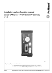
Cement Curing Autoclave
User Manual
100072577
Revision H
Cement Curing Autoclave User Manual
©2015 Fann Instrument Company
Houston, Texas, USA
All rights reserved. No part of this work covered by the copyright hereon may be
reproduced or copied in any form or by any means (graphic, electronic, or
mechanical) without first receiving the written permission of Fann Instrument
Company, Houston, Texas, USA.
Printed in USA
The information contained in this document includes concepts,
methods, and apparatus which may be covered by U. S. Patents
FANN® reserves the right to make improvements in design,
construction, and appearance of our products without prior notice.
FANN® and the FANN® logo are registered trademarks of Fann Instrument Company
in the United States and/or other countries.
UCA™ is a trademark of Fann Instrument Company.
Contact FANN®
Phone
TELEPHONE:281-871-4482
TOLL FREE:800-347-0450
FAX:281-871-4358
Mail
Fann Instrument Company
P. O. Box 4350
Houston, Texas, 77210 USA
Location
Fann Instrument Company
14851 Milner Road, Gate 5
Houston, Texas 77032 USA
Online
www. fann. com
fannmail@fann. com
Cement Curing Autoclave User Manual
Contents
1
Introduction.............................................................................................................1
1.1 Cement Curing Autoclave ................................................................................... 1
1.2 Function ............................................................................................................... 1
1.3 Features ................................................................................................................ 2
2
Safety.......................................................................................................................4
2.1 Machine Hazards ................................................................................................. 4
2.2 Ergonomic Considerations ................................................................................... 5
3
Features and Specifications ..................................................................................6
3.1
3.2
3.3
3.4
3.5
4
Installation.............................................................................................................26
4.1
4.2
4.3
4.4
5
Cement Curing Autoclave Mechanical ................................................................ 6
Cement Curing Molds .......................................................................................... 7
Cement Curing Autoclave Controls and Indicators ............................................. 9
Temperature Controller Configuration .............................................................. 10
Pressurizing the Cement Curing Autoclave ....................................................... 24
Parts of the Cement Curing Autoclave .............................................................. 26
Other Parts ......................................................................................................... 26
Locating the Cement Curing Autoclave ............................................................ 26
Electric Power Supply ....................................................................................... 26
Operation...............................................................................................................28
5.1
5.2
5.3
5.4
5.5
5.6
5.7
5.8
5.9
5.10
5.11
Sample Preparation ............................................................................................ 28
Prepare the Cube Mold ...................................................................................... 28
Prepare the Cement Slurry ................................................................................. 32
Fill the Molds ..................................................................................................... 32
Place molds into chamber .................................................................................. 35
Place chamber in heating jacket......................................................................... 39
Pressurize the chamber ...................................................................................... 41
Running a test .................................................................................................... 41
Ending the test ................................................................................................... 43
Remove the chamber ......................................................................................... 43
Cleaning the molds, pressure chamber, and autoclave ...................................... 44
6
Analyzing Results ................................................................................................. 45
7
Troubleshooting and Maintenance ...................................................................... 46
100072577
Revision H
ii
Cement Curing Autoclave User Manual
7.1 Eurotherm 2404 Temperature Calibration ......................................................... 46
7.2 Troubleshooting Tables ..................................................................................... 46
8
Accessories .......................................................................................................... 50
8.1 Hand Pressure Pump .......................................................................................... 50
9
Parts Lists .............................................................................................................51
10 Warranty and Returns .......................................................................................... 66
10.1 Warranty ............................................................................................................ 66
10.2 Return of Items .................................................................................................. 66
100072577
Revision H
iii
Cement Curing Autoclave User Manual
List of Figures
Figure 1-1 Cement Curing Autoclave, front view ............................................................. 2
Figure 1-2 Cement Curing Autoclave, back view ............................................................ 3
Figure 3-1
Manual Needle Valve and Pressure Relief Valve ........................................ 7
Figure 3-2 Pressure Manifold, Thermocouple, Pressure Gauge ..................................... 7
Figure 3-3 Cement Mold ..................................................................................................8
Figure 3-4 Cement Mold Clamp .....................................................................................8
Figure 3-5 Cement Mold Base .........................................................................................9
Figure 3-6 Temperature Controller, Main Power, Heat switch ....................................... 10
Figure 3-7 Water Expelled as Lid is Closed ................................................................... 24
Figure 3-8 Pressure source connected to needle valve ................................................. 25
Figure 3-9 Initial pressure (left), increased pressure from temperature rise (right) ......... 25
Figure 5-1 Pins align the mold halves ............................................................................ 28
Figure 5-2 Clamps hold mold halves together ............................................................... 29
Figure 5-3 Grease mold for base plate .......................................................................... 30
Figure 5-4 Tighten base plate to mold ........................................................................... 30
Figure 5-5 Grease mold interior ..................................................................................... 31
Figure 5-6 Mixing Cement Slurry ................................................................................... 32
Figure 5-7 Filling mold .................................................................................................. 33
Figure 5-8 Leveling cement .......................................................................................... 33
Figure 5-9 Grease cover plate ...................................................................................... 34
Figure 5-10 Cover plate................................................................................................. 34
Figure 5-11 Lower mold into chamber – 1 .................................................................... 35
Figure 5-12 Lower mold into chamber – 2 .................................................................... 35
Figure 5-13 Grease chamber threads ........................................................................... 36
Figure 5-14 Tighten lid .................................................................................................. 37
Figure 5-15 Water expelled as lid tightened .................................................................. 37
Figure 5-16 Handle spring loaded pin retracted ............................................................. 38
Figure 5-17 Handle and manifold on chamber ............................................................... 38
Figure 5-18 Place chamber into autoclave, remove handle ........................................... 39
Figure 5-19 Attach valve and manifold .......................................................................... 40
100072577
Revision H
iv
Cement Curing Autoclave User Manual
Figure 5-20 Connect thermocouple cable ...................................................................... 40
Figure 5-21 Set initial chamber pressure ....................................................................... 41
Figure 5-22 Initial pressure (left), increased pressure from temperature rise (right) ....... 42
Figure 7-1 Power fuse holders ...................................................................................... 47
Figure 8-1 101443558 PUMP ASSY HYD CEMENT CURING AUTOCLAVE, HAND
OPERATED ................................................................................................ 50
Figure 9-1 100053968 – Installation, Chamber Assembly, Standard, 1200ML, 2 Cube . 51
Figure 9-2 101443558 A PUMP ASSY HYD CEMENT CURING AUTOCLAVE, HAND
OPERATED ................................................................................................ 53
Figure 9-3 100053968 Kit, Installation, Tools & Manual (not shown), Autoclave,
Standard, 1200ml ........................................................................................ 55
Figure 9-4 Assembly, Cement Curing Autoclave ........................................................... 56
Figure 9-5 Electrical Schematic – 115V Cement Curing Autoclave................................ 64
Figure 9-7 Electrical Schematic – 230V Cement Curing Autoclave................................ 65
100072577
Revision H
v
Cement Curing Autoclave User Manual
List of Tables
Table 3-1 Cement Curing Autoclave Specifications ...................................................... 6
Table 7-1 Problems with General System .................................................................... 47
Table 7-2 Temperature Problems ................................................................................ 48
Table 7-3 Pressure Problems ...................................................................................... 48
Table 7-4 Chamber Lid Problems ................................................................................ 49
Table 9-1 100053968 NX INSTALLATION, CHAMBER ASSEMBLY, STANDARD,
1200ML, 2 CUBE ........................................................................................ 52
Table 9-2 101443557 A PUMP ASSY HYD CEMENT CURING AUTOCLAVE, HAND
OPERATED ................................................................................................ 54
Table 9-3 101497200 K CEMENT CURING AUTOCLAVE 115V TWO 2-INCH CUBE
MOLDS ....................................................................................................... 57
Table 9-4 101533369 J CEMENT CURING AUTOCLAVE 230V TWO 2-INCH CUBE
MOLDS ....................................................................................................... 60
100072577
Revision H
vi
Cement Curing Autoclave User Manual
1 Introduction
1.1
Cement Curing Autoclave
The Cement Curing Autoclave is an apparatus used to cure cement slurry
samples under elevated hydrostatic pressure and temperature. The cement
slurry samples are contained in one or two 2 inch cube molds, surrounded by
water (or oil), within the pressure chamber. The autoclave includes a heating
jacket which completely surrounds the cement curing pressure chamber,
temperature controller, thermocouple, pressure gauge, adjustable pressure
regulator, and manual fill and bleed valve.
The Cement Curing Autoclave requires an external pressure source, such as
compressed nitrogen gas or a hydraulic pump, capable of providing pressure
up to 3,000 PSI.
1.2
Function
The Cement Curing Autoclave cures cement slurry samples under elevated
pressure and temperature to prepare them for destructive compressive-strength
tests. These tests help determine compliance to American Petroleum Institute
(API) Specification 10A, Specification for Cements and Materials for Well
Cementing. This device meets the requirements for pressurized cement curing
equipment found in API Specification 10A, and API Recommended Practice
10B, Recommended Practice for Testing Well Cements.
After the curing period, the samples are removed from the single-cube molds
and tested to determine their compressive strength.
The pressure relief valve prevents the pressure chamber from exceeding 3,000
PSI (20.7 MPa).
The desired temperature for curing the cement samples is set on the
temperature controller, which automatically maintains that temperature
throughout the curing period. The maximum recommended curing
temperature is 400 Degrees F (204 Degrees C). A thermostat in the heating
jacket is set for an upper limit of 450 Degrees F (232 Degrees C) for safety.
The practice of removing the curing chamber and cooling it under
water is very dangerous. It is not recommended because of the
danger of severe burns if touched or accidentally dropped. Also
use extreme caution when placing a hot chamber in water. Hot
steam generated when the water hits the hot chamber can cause
severe burns.
100072577
Revision H
1
Cement Curing Autoclave User Manual
1.3
Features
•
•
•
•
•
•
•
Single chassis contains all components in a durable stainless steel case.
Insulated heating jacket reduces heating of the work area.
Two two-inch cube molds and covers are included.
Adjustable pressure relief valve.
Programmable temperature controller.
Removable chamber carrying handle.
Adjustable support feet.
Figure 1-1
Cement Curing Autoclave, front view
100072577
Revision H
2
Cement Curing Autoclave User Manual
Figure 1-2
Cement Curing Autoclave, back view
100072577
Revision H
3
Cement Curing Autoclave User Manual
2 Safety
2.1
Machine Hazards
2.1.1
Pressure
Pressurized air and water lines present a hazard if not
depressurized before maintenance or disassembly.
High pressure hydraulic lines are a hazard because they can hold
up to 3,000 PSI (20.7 MPa). These lines are stainless steel or
reinforced hose. Operators must ensure that the pressure in these
lines has been reduced to zero before attempting to disassemble
any high pressure lines. Open the pressure manifold valve.
Confirm that all pressure in the system has been relieved by
observing the pressure gauge on the top of the chamber.
2.1.2
Temperature
The pressure chamber has an electric heating jacket that can heat
the cement slurry to 400°F (205°C). The metal jacket itself can be
considerably hotter, even over 600°F (315°C). Before removing
the pressure chamber, or performing any work on the heating
jacket, allow it to cool to below 120°F (49°C). Monitor the
temperature by observing the temperature controller display when
the chamber is in the heating jacket.
2.1.3
Steam
Water is commonly used to pressurize the cement slurry being
cured. When heat is applied, there is the potential for the water to
become high temperature steam. Because of the risk of burn, body
parts should be kept away from the manual pressure relief valve
(needle valve) when it is being opened.
As the automatic pressure relief valve opens, small amounts of hot
water and steam will be released, which are a burn hazard.
2.1.4
Electrical
The power source for the Cement Curing Autoclave is 115 or 230
Volts. There are electrically active terminals inside the instrument
when the power switch is turned off. Physically disconnect the
power cord from the outlet and instrument before attempting any
electrical or mechanical maintenance. Refer to the electrical
schematic before performing any maintenance or troubleshooting.
100072577
Revision H
4
Cement Curing Autoclave User Manual
2.2
Ergonomic Considerations
After the Cement Curing Autoclave is installed, it is uncommon for it to be
frequently moved. The physical location needs to have access to the required
electric power source, pressure source (compressed gas or hydraulic pump),
and be sufficiently sturdy to support the combined weight of the Cement
Curing Autoclave, pressure chamber, and cube molds, which is approximately
137 pounds (64 kg).
In routine cement slurry curing, the combined weight of the pressure chamber,
cement molds, cement, pressurizing water or oil, manifold, and handle must
be lifted fully from the heating jacket a distance of 8-1/2 inches (21.6 cm).
This weight varies with the number of molds and the cement slurry being
cured, and approaches 69 pounds (31.4 kg). Placing the top surface of the
Cement Curing Autoclave at 24–36 in (61–91 cm) from the floor is an
appropriate height for most people to lift the cement curing chamber.
100072577
Revision H
5
Cement Curing Autoclave User Manual
3 Features and Specifications
Table 3-1 Cement Curing Autoclave Specifications
Category
Specification
Maximum Temperature
400°F (205°C)
Maximum Pressure
3,000 PSI (20.7 mega Pascal [MPa])
Heating Rate
8°F [4. 4°C] per minute maximum
Curing Chamber Volume (empty)
40.1 ounces (oz) (1,200 milliliters [ml])
Width
21.5 inches (in) (54.6 centimeters [cm])
Depth
16.5 in (41.9 cm)
Height
13.5-14.5 in (34.3-36.8 cm)
Weight
116 pounds (lb) (53 kilograms [kg])
Pressure Connection
1/8 Female NPT, located on the manual
pressure release valve
Single phase, AC, 50–60 Hertz (Hz) -
Voltage and Current
115V, 15A, NEMA 5-20P plug or
230V, 10A, NEMA 6–15P plug
3.1
Cement Curing Autoclave Mechanical
The manual needle valve in the pressure manifold controls the pressure going
into the curing chamber. During testing, the needle valve is normally closed.
At the conclusion of a test, after the temperature is below 120 Degrees F (48.9
Deg C), the needle valve can be opened to completely release the pressure.
Pressures above 3,000 PSI (20.68 MPa) are automatically vented by the
pressure relief valve, which functions as an over-pressure safety device.
The chamber pressure is shown on a pressure gauge installed directly into the
top of the curing chamber.
100072577
Revision H
6
Cement Curing Autoclave User Manual
Figure 3-1
Manual Needle Valve and Pressure Relief Valve
Figure 3-2
Pressure Manifold, Thermocouple, Pressure Gauge
3.2
Cement Curing Molds
Two brass alloy molds, internally measuring 2 inches X 2 inches X 2 inches
(5.08 cm X 5.08 cm X 5.08 cm) are provided with each Cement Curing
Autoclave. The two mold halves are aligned with dowel pins, and clamped
together with threaded sleeves. Two flat head screws fasten the bottom plate
to the two mold halves. This arrangement allows the mold to be removed
without damaging the cured cement specimen, and for thorough clean-up.
100072577
Revision H
7
Cement Curing Autoclave User Manual
Figure 3-3
Cement Mold
Figure 3-4
Cement Mold Clamp
100072577
Revision H
8
Cement Curing Autoclave User Manual
Figure 3-5
Cement Mold Base
3.3
Cement Curing Autoclave Controls and Indicators
The main power switch illuminates when electric power is applied to the
cement curing autoclave circuits.
The heat switch, located below the main power switch on the front panel,
enables and disables the heater circuit without interrupting power to the entire
instrument.
The temperature controller regulates the power applied to the heater circuit to
achieve and maintain the desired temperature inside the curing chamber. It
constantly compares the desired temperature (set point) to the temperature
reading from the curing chamber thermocouple and adjusts the heating cycle
to achieve and/or maintain the desired temperature. It continuously displays
the current and set point temperatures.
100072577
Revision H
9
Cement Curing Autoclave User Manual
Figure 3-6
Temperature Controller, Main Power, Heat switch
3.4
Temperature Controller Configuration
The tables in this section contain the factory settings for the Eurotherm
Model 2404 temperature controller when it is configured for the Cement
Curing Autoclave. It is rare that the majority of these settings will need to be
changed. They are provided for reference should the temperature controller
respond in an unexpected manner, and incorrect settings are suspected.
100072577
Revision H
10
Cement Curing Autoclave User Manual
100072577
Revision H
11
Cement Curing Autoclave User Manual
1. Press
until the display shows
2. Press
to select the Config password (2)
3. ‘Pass’ is displayed momentarily.
Press
to Configuration (ConF)
Name
to select
Value
Parameter Description
or
to change
Ctrl
Control Type
PID
Act
Control Action
ReU
Cool
Type of Cooling
Lin
Ti.Td
Integral & derivative time units
SEc
dtYP
Derivative type
PU
m-A
Front panel Auto/Man button
EnAb
r-h
Front panel Run/Hold button
EnAb
PwrF
Power feedback
on
Fwd.t
Feed forward type
nonE
Sb.tr
Sensor break output
Sb.OP
FOP
Forced manual output
no
bcd
BCD input function
nonE
GSch
Gain schedule enable
no
LC.HI
100072577
0
Revision H
12
Cement Curing Autoclave User Manual
Press
to Process Value (PU) Configuration
Name
Value
to select
Parameter Description
or
uniT
Instrument units
ºF
dEc.P
Decimal places in the display
nnn.n
rnG.L
Range low
-199.9
rnG.h
Range high
999.9
Press
to Input (iP) Configuration
Name
Value
to select
Parameter Description
or
to change
inPt
Input type
J.tc
CJC
Cold junction compensation
Auto
imP
Sensor break impedance
Auto
Press
to Set Point (SP) Configuration
Name
to select
Value
Parameter Description
or
to change
nSP
Number of setpoints
2
rm.tr
Remote tracking
OFF
m.tr
Manual track
OFF
rmP.U
Setpoint rate limit units
PSec
rmt
100072577
to change
Remote setpoint
configuration
Revision H
nonE
13
Cement Curing Autoclave User Manual
Press
to Alarm (AL) Configuration
Name
to select
Value
Parameter Description
or
AL 1
Alarm 1 Type
OFF
Ltch
Latching
no
bLoc
Blocking
no
AL 2
Alarm 2 Type
OFF
Ltch
Latching
no
bLoc
Blocking
no
AL 3
Alarm 3 Type
OFF
Ltch
Latching
no
bLoc
Blocking
no
AL 4
Alarm 4 Type
OFF
Ltch
Latching
no
bLoc
Blocking
no
Press
to Program (PROG) Configuration
Name
to select
Value
Parameter Description
or
to change
PtYP
Programmer type
1
HbAC
Holdback
SEG
Pwr.F
Power fail recovery
cont
Srvo
100072577
to change
Starting setpoint of a
program (Servo point)
Revision H
To.PU
14
Cement Curing Autoclave User Manual
Press
to Digital Input (LA) Configuration
Name
to select
Value
Parameter Description
or
iD
Identity
LoG.i
Func
Function of input
nonE
Press
to Digital Input (Lb) Configuration
Name
to select
Value
Parameter Description
or
to change
iD
Identity
LoG.i
Func
Function of input
nonE
Press
to Comms 1 Module (HA) Configuration
Name
to select
iD
Func
100072577
to change
Value
Parameter Description
Identity of the module
installed
Function of input
Revision H
or
to change
nonE
nonE
15
Cement Curing Autoclave User Manual
Press
to Comms 2 Module (JA) Configuration
Name
Value
to select
Parameter Description
or
Identity of the module
iD
nonE
installed
Function of input
Func
Press
nonE
to Module 1 (1A) Configuration
Name
Value
to select
Parameter Description
or
to change
id
Identify of module installed
LoG
Func
Function
HEAt
%PID demand signal giving
UAL.L
0
minimum output
%PID demand signal giving
UAL.H
100
maximum output
Out.L
Minimum average power
0.0
Out.H
Maximum average power
100.0
Press
to Module 2 (2A) Configuration
Name
to select
100072577
to change
Value
Parameter Description
or
to change
id
Identify of module installed
nonE
Func
Function
nonE
Revision H
16
Cement Curing Autoclave User Manual
Press
to Module 3 (3A) Configuration
Name
Value
to select
Parameter Description
or
to change
id
Identify of module installed
nonE
Func
Function
nonE
Press
to Module 4 (4A) Configuration
Name
to select
Value
Parameter Description
or
to change
id
Identify of module installed
nonE
Func
Function
nonE
Press
to Calibration (CAL) Configuration
Name
to select
Value
Parameter Description
or
to change
rcAL
Calibration point
nonE
UCAL
User calibration enable
no
Pt1.L
Low calibration point for Input 1
0.0
Pt1.H
High calibration point for Input 1
999.9
OF1.L
Offset Low for Input 1
0.0
OF1.H
Offset High for Input 1
0.0
100072577
Revision H
17
Cement Curing Autoclave User Manual
Press
to EXIT
to select YES
Press
UNIT WILL RESTART
Press
100072577
to select FuLL
Revision H
18
Cement Curing Autoclave User Manual
Press
to Program run list (run)
Name
Value
to select
Parameter Description
or
to change
StAt
Program status
OFF
FASt
Fast run through program
no
Flash active segment in the
lower readout of the home
SEG.d
YES
display
Press
to Program Edit List (ProG)
Name
to select
100072577
Value
Parameter Description
or
to change
Hb U
Holdback value
10.0
rmP.U
Ramp units
min
dwL.U
Dwell units
min
CYC.n
Number of program cycles
1
SEG.n
Segment number
1
tYPE
Segment type
rmPr
Hb
Holdback type
OFF
tGt
Target setpoint
135
rAtE
Ramp rate
.3
SEG.n
Segment number
2
tYPE
Segment type
rmPr
Hb
Holdback type
bAnd
tGt
Target setpoint
190
rATe
Ramp rate
0.3
SEG.n
Segment number
3
tYPE
Segment type
End
End.t
End of program
dwEll
Revision H
19
Cement Curing Autoclave User Manual
Press
to Alarm List (AL)
Name
to select
Value
Parameter Description
or
Lbt
Loop break time in minutes
OFF
diAG
Enable Diagnostic alarms
no
Press
to PID list (Pi d)
Name
to select
Value
Parameter Description
or
to change
SEt
Pid.1 Or Pid.2 selected
Pid.1
Pb
Proportional Band
0.8
Ti
Integral Time in seconds
1700
Td
Derivative Time in seconds
65
rES
Manual Reset (%)
0.0
Hcb
High cutback
OFF
Lcb
Low cutback
0.1
Pb2
Proportional Band Pid 2
0.8
Ti2
Td2
100072577
to change
Integral Time in seconds
Pid2
Derivative Time in seconds
Pid2
1700
65
rES2
Manual Reset (%) Pid 2
0.0
Hcb2
High cutback Pid2
OFF
Lcb2
Low cutback Pid2
0.1
Revision H
20
Cement Curing Autoclave User Manual
Press
to Setpoint list (SP)
Name
to select
Value
Parameter Description
or
uniT
Instrument units
ºF
dEc.P
Decimal places in the display
nnn.n
rnG.L
Range low
-199.9
rnG.h
Range high
999.9
Press
to Input list (iP)
Name
to select
Value
Parameter Description
or
to change
uniT
Instrument units
ºF
dEc.P
Decimal places in the display
nnn.n
rnG.L
Range low
-199.9
rnG.h
Range high
999.9
Press
to Output list (oP)
Name
to select
100072577
to change
Value
Parameter Description
or
to change
uniT
Instrument units
ºF
dEc.P
Decimal places in the display
nnn.n
rnG.L
Range low
-199.9
rnG.h
Range high
999.9
Revision H
21
Cement Curing Autoclave User Manual
Press
to Information list (info)
Name
Value
to select
Press
Parameter Description
or
to change
uniT
Instrument units
ºF
dEc.P
Decimal places in the display
nnn.n
rnG.L
rnG.h
Range low
Range high
-199.9
999.9
to Page to ACCS list
‘Pass’ is displayed momentarily.
Press
100072577
to Edit
Revision H
22
Cement Curing Autoclave User Manual
to Program Read
Press
Name
Value
to select
Parameter Description
to change
uniT
Instrument units
ºF
dEc.P
Decimal places in the display
nnn.n
rnG.L
Range low
Range high
-199.9
rnG.h
Press
or
999.9
to Page to ACCS list
‘Pass’ is displayed momentarily.
Press
Press
100072577
to OPEr
to Home View
Revision H
23
Cement Curing Autoclave User Manual
3.5
Pressurizing the Cement Curing Autoclave
Cement samples being cured in the Cement Curing Autoclave are pressurized
by a hydraulic fluid, normally water. The initial pressure can be provided by a
hand or electric pump, or by an inert compressed gas, such as nitrogen. For
either pressurizing method, the pressurizing chamber and manifold should be
filled as much as possible with a non-compressible fluid, such as water. This
minimizes the time required to pressurize to the desired pressure and increases
safety.
Figure 3-7
Water Expelled as Lid is Closed
Either pressure source is connected to the open 1/8 NPT port on the needle
valve. After reaching the desired pressure, the needle valve can be closed and
the pressure source disconnected.
100072577
Revision H
24
Cement Curing Autoclave User Manual
Figure 3-8
Pressure source connected to needle valve
As the curing temperature increases during the curing process, an automatic
pressure relief valve prevents the chamber internal pressure from exceeding
3,000 PSI. This spring loaded valve releases small amounts of the
pressurizing fluid (water).
Figure 3-9
Initial pressure (left), increased pressure from temperature rise (right)
100072577
Revision H
25
Cement Curing Autoclave User Manual
4 Installation
4.1
Parts of the Cement Curing Autoclave
4.1.1
4.2
Reference: see 1 Introduction.
Other Parts
4.2.1
Several smaller items are packed separate from the Cement Curing
Autoclave, to protect them during shipping. When unpacking the Cement
Curing Autoclave, verify that you have received the pressure chamber,
thermocouple cable, power cable, two cement molds and two covers,
mold handling tool, chamber wrench, Vise Grip chain tool, and
instruction manuals.
4.3
Locating the Cement Curing Autoclave
4.3.1
Locate the Cement Curing Autoclave(s) relative to the cement
sample preparation area, as desired.
4.3.2
Locate a compressed, inert gas cylinder, or hydraulic pump, near
the Cement Curing Autoclave, or where the pressure chamber will be
pressurized.
4.3.3
The tools to fully close and open the chamber cap should be located
near either the cement sample preparation area, near the Cement Curing
Autoclave, or in a work area which is convenient to both. The cement
mold handling tool should be in the same area.
4.3.4
A water source should be nearby, if water will be used to surround
and pressurize the cement samples.
4.3.5
Tools for disassembling and cleaning the molds, and properly
disposing of the sample debris, should be nearby.
4.3.6
Adjust the four feet beneath the cabinet to level the Cement Curing
Autoclave from side-to-side, and front-to-back. Once the cabinet is level,
secure the locking nuts on the adjustable feet to prevent inadvertent
changes.
4.4
Electric Power Supply
4.4.1
The Cement Curing Autoclave is supplied with a 5-ft power cord,
with either a NEMA 5-20P (115V) or 6–15P (230V) plug, depending
upon the voltage ordered. Because of the diversity in types of electrical
outlets throughout the world, it may be necessary to replace this plug.
Alternatively, the Cement Curing Autoclave can be directly wired into an
100072577
Revision H
26
Cement Curing Autoclave User Manual
electrical disconnect switch. Regardless of the connection, ensure that
proper power is provided.
4.4.2
The electric power supply must be single-phase and 50-60 Hz.
4.4.2.1
115 VAC, 15 A for 115 VAC Cement Curing Autoclaves
4.4.2.2
230 VAC, 10 A for 230 VAC Cement Curing Autoclaves
4.4.3
Connect the power cord to the Cement Curing Autoclave, and then
connect the power cord to the power source.
100072577
Revision H
27
Cement Curing Autoclave User Manual
5 Operation
5.1
Sample Preparation
5.1.1
Preparation of the cement slurry, curing, and strength testing of the
cured sample should be done by following the procedures in the latest
edition of the API Recommended Practice for Testing Oil Well Cements
and Cement Additives (API RP 10B). This publication is available from
the American Petroleum Institute, Division of production, 300 Corrigan
Tower Building, Dallas, Texas, 75201, USA. These procedures should be
reviewed prior to using the Cement Curing Autoclave.
5.2
Prepare the Cube Mold
5.2.1
One or two, 2 inch, cube molds are used with the Cement Curing
Autoclave chamber. To prevent the cement slurry from seeping into the
joints between the sides and base plates, apply a thin coat of grease to the
bottom edges of the mold. Keep and use like numbered cement mold
halves together.
Figure 5-1
Pins align the mold halves
100072577
Revision H
28
Cement Curing Autoclave User Manual
Figure 5-2
Clamps hold mold halves together
100072577
Revision H
29
Cement Curing Autoclave User Manual
Figure 5-3
Grease mold for base plate
5.2.2
Attach the base plate to the mold using two flat head machine
screws.
Figure 5-4
Tighten base plate to mold
100072577
Revision H
30
Cement Curing Autoclave User Manual
5.2.3
Apply a thin coat of grease on the mold interiors and the base plates
to keep the cement slurry from sticking. Excess grease at the inside joints
of the molds will decrease the actual volume of the cement cube and can
result in inaccurate compressive strength tests.
Figure 5-5
Grease mold interior
100072577
Revision H
31
Cement Curing Autoclave User Manual
5.3
Prepare the Cement Slurry
5.3.1
Mix the cement slurry according to API RP 10B.
Figure 5-6
Mixing Cement Slurry
5.4
Fill the Molds
5.4.1
Pour the cement slurry into the assembled mold. Repeatedly
puddle and stir the slurry, then remove the excess with a straight edge to
level the slurry with the top of the molds. See API RP 10B.
100072577
Revision H
32
Cement Curing Autoclave User Manual
Figure 5-7
Filling mold
Figure 5-8
Leveling cement
100072577
Revision H
33
Cement Curing Autoclave User Manual
5.4.2
To keep the pressurizing water from contaminating the slurry,
apply a thin layer of grease to the top edges of the mold, and to the edges
of the mold cover plate.
Figure 5-9
Grease cover plate
5.4.3
Put the cover plate on the mold.
Figure 5-10
Cover plate
100072577
Revision H
34
Cement Curing Autoclave User Manual
5.5
Place molds into chamber
5.5.1
Use the cube mold removal tool to lower one or both molds into the
Cement Curing Autoclave Chamber. Once the molds are in the chamber,
avoid tipping the chamber, which may displace the covers.
Figure 5-11
Lower mold into chamber – 1
Figure 5-12
Lower mold into chamber – 2
100072577
Revision H
35
Cement Curing Autoclave User Manual
5.5.2
Coat the chamber threads with grease.
Figure 5-13
Grease chamber threads
5.5.3
Fill the chamber with water to halfway up the threads. This ensures
all air will be removed from the chamber when the lid is installed. See
API RP 10B.
5.5.4
Inspect the chamber lid O-ring for cuts or other damage. If it is
damaged, it should be replaced.
5.5.5
Grease the lid O-ring and lid threads.
5.5.6
Install the lid onto the chamber. Fully tighten the lid into the
chamber using the pressure vessel wrench and Vise Grip chain clamp.
When the lid is fully seated, loosen it 1/8 to 1/4 turn. This helps to ensure
the lid does not become jammed.
100072577
Revision H
36
Cement Curing Autoclave User Manual
Figure 5-14
Tighten lid
Figure 5-15
Water expelled as lid tightened
5.5.6.1 Attach the removable chamber handle by pulling the
spring loaded pins away from the handle. Place the handle over the lid, and
release the spring loaded pins to engage the holes in the lid.
100072577
Revision H
37
Cement Curing Autoclave User Manual
Figure 5-16
Handle spring loaded pin retracted
Figure 5-17
Handle and manifold on chamber
100072577
Revision H
38
Cement Curing Autoclave User Manual
5.6
Place chamber in heating jacket.
5.6.1
Using the handle, carefully carry the assembled chamber to the
autoclave.
5.6.2
Carefully lower the chamber into the heating jacket.
Figure 5-18
Place chamber into autoclave, remove handle
5.6.3
Remove the carrying handle.
5.6.4
Connect the pressurizing manifold to the brass coupling on the
chamber lid. Tighten the manifold coupling nut using hand force only.
100072577
Revision H
39
Cement Curing Autoclave User Manual
Figure 5-19
Attach valve and manifold
5.6.5
Connect the thermocouple cable to the thermocouple in the curing
chamber lid.
Figure 5-20
Connect thermocouple cable
100072577
Revision H
40
Cement Curing Autoclave User Manual
5.7
Pressurize the chamber
5.7.1
Connect the pressure source to the manual valve.
5.7.2
Open the manual valve at least one (1) and not more than two (2)
full turns.
5.7.3
Operate the pressure source to increase the pressure inside the
curing chamber to the desired initial value as required for the test. See
API RP 10B.
5.7.4
Close the manual valve to retain the chamber pressure.
5.7.5
If desired, the pressure source may be disconnected.
Figure 5-21
Set initial chamber pressure
5.8
Running a test
5.8.1
Adjust the set point of the temperature controller to the desired
maximum temperature. See API RP 10B for settings.
5.8.2
Program Temperature Control for a Test
5.8.2.1
From the home display, press
until you reach ’ProG
LiSt’. Press.
5.8.2.2
be changed. Press.
Use the arrow keys to select the number of the program to
5.8.2.3 For each program setting, use
or
to change the
displayed value. After releasing the button, the display will blink to show the
controller has accepted the new value.
100072577
Revision H
41
Cement Curing Autoclave User Manual
5.8.2.4 Continue to press
until you have reviewed or
changed the desired program values and return to the ’ProG LiSt’ display.
5.8.2.5
5.8.3
Press the Run/Hold button.
Turn the heater control switch to the on position.
5.8.4
Observe the temperature controller for flashing of the OP1 indicator
and the temperature increasing. The temperature controller will
continually turn on and off the heater until the slurry thermocouple
reaches the desired temperature.
5.8.5
Frequently monitor the chamber pressure gauge as the slurry curing
progresses. As the water inside heats up, it will expand and increase the
pressure. Reduce the pressure by slowly opening the needle valve so the
maximum pressure specified in API RP 10B is not exceeded. The
automatic relief valve will bleed off potentially hazardous pressure (if it is
properly adjusted).
Hot water and/or steam may be violently expelled when the
needle valve is opened. Keep all body parts clear of the valve
outlet when it is being opened.
Figure 5-22
Initial pressure (left), increased pressure from temperature rise (right)
100072577
Revision H
42
Cement Curing Autoclave User Manual
5.9
Ending the test
5.9.1
When the required curing period has ended, cool the sample and
chamber, maintaining pressure, according to “Curing at Pressures Above
Atmospheric” in API RP 10B.
5.9.2
At the specified time (see “Curing at Pressures Above
Atmospheric” in API RP 10B), when the chamber has cooled, slowly
release all remaining pressure by opening the needle valve.
Hot water and/or steam may be violently expelled when the
needle valve is opened. Keep all body parts clear of the valve
outlet when it is being opened.
5.9.3
5.10
Turn the heat switch to the OFF position.
Remove the chamber
5.10.1 Disconnect the cable from the thermocouple and lay the cable
aside.
5.10.2
Remove the pressure manifold assembly and lay it aside.
5.10.3 If previously removed, re-attach the carrying handle and lift the
chamber clear of the heating jacket and move it to the desired work area.
5.10.4 Unscrew the chamber lid using the wrenches provided. Remove
the chamber lid and set it aside.
5.10.5
Remove the molds from the chamber using the mold lifting tool.
5.10.6 Follow the procedures in “Curing at Pressures Above Atmospheric”
in API RP 10B to remove the cured cement specimens from the molds,
process, and test them.
100072577
Revision H
43
Cement Curing Autoclave User Manual
5.11
Cleaning the molds, pressure chamber, and autoclave
5.11.1 Wipe all cement remnants and grease from the molds, lid and inside
of the chamber body. Pay particular attention to clean the threads and the
O-ring groove in the lid.
5.11.2
Remove cement particles using a metal spatula or wire brush.
5.11.3 Remove any cement film by dipping the part in 15-20 percent
hydrochloric acid. Let the parts sit for several minutes, then brush clean
and rinse the parts thoroughly with water. Properly disposed of the waste
acid.
5.11.4
Remove grease film with a solvent
5.11.5
Carefully dry the parts.
5.11.6 Inspect the lid O-ring for damage, and replace those which are
damaged.
5.11.7
100072577
Clean and wipe all surfaces on the Cement Curing Autoclave.
Revision H
44
Cement Curing Autoclave User Manual
6 Analyzing Results
The Cement Curing Autoclave cures cement slurry specimens for compressive
strength testing by other instruments.
100072577
Revision H
45
Cement Curing Autoclave User Manual
7 Troubleshooting and Maintenance
7.1
Eurotherm 2404 Temperature Calibration
The basic calibration of the Eurotherm 2404 temperature controller is highly
stable and set for life. Rarely, it may be desired to offset the factory
calibration to set the controller to another reference standard, to suit the
characteristics of a particular installation, or to remove long term drift in the
factory set calibration.
Should re-calibration be desired, see the Eurotherm 2404 thermocouple
instruction manual for the detailed procedure.
7.2
Troubleshooting Tables
These tables are provided to assist in troubleshooting when a variety of
problems arise while operating the Cement Curing Autoclave. Included in the
tables are symptoms of the problem, possible causes of the problem, and
possible solutions to the problem. The tables are grouped according to topic.
The following troubleshooting tables are provided in this section:
•
•
•
•
100072577
General troubleshooting
Temperature troubleshooting
Pressure troubleshooting
Chamber lid troubleshooting
Revision H
46
Cement Curing Autoclave User Manual
Table 7-1 Problems with General System
Problem or Symptom
The system does not power
up.
Possible Cause
Corrective Action
The power fuses are blown.
Check/replace the power
fuses located on the back of
the unit. See Figure 7-4.
The power switch has
malfunctioned or failed.
Check/replace the power
switch.
The power wiring is faulty.
Check/repair the power
wiring. Refer to the wiring
diagram.
The power source is
disconnected or turned off.
Check the power source.
Figure 7-1
Power fuse holders
100072577
Revision H
47
Cement Curing Autoclave User Manual
Table 7-2 Temperature Problems
Problem or Symptom
The system does not heat
up, but the heater indicator
in the temperature
controller is on.
Possible Cause
Corrective Action
The heater wiring is faulty.
Check/repair the heater
wiring. Refer to the wiring
diagram.
The over temperature
switch has failed.
Check and/or replace the
over-temp switch
The heater malfunctioned or Check and/or replace the
failed.
heater.
Solid state heater relay has
failed.
Check/replace, if necessary.
The heater fuses are blown.
Check/replace the heater
fuses.
The heater control
electronics malfunctioned
or failed.
Check the heater solid-state
relay, and the heater circuit
wiring. Refer to the wiring
diagram.
The temperature reading is
unreasonably high
(<1,000°F).
Possible open circuit in
thermocouple or
thermocouple cables.
Look for and repair the
broken wire or loose
connection.
The temperature reading is
about room temperature
even though the chamber is
hot.
Possible short circuit in
thermocouple or
thermocouple cable.
Look for and repair the
short in the thermocouple or
thermocouple cable.
The system does not heat
up, and the heater indicator
in the temperature
controller is off.
Table 7-3 Pressure Problems
Problem or Symptom
The system does not hold
pressure.
Possible Cause
The manifold has a leak.
Check, repair, or replace the
manifold.
The lid or chamber has a
leak.
Check the lid O-ring seal
for damage or debris on the
surfaces, and clean or
replace.
The pressure gauge does not The pressure gauge is
zero.
faulty.
100072577
Corrective Action
Revision H
Test the pressure gauge, and
replace if found faulty.
48
Cement Curing Autoclave User Manual
Table 7-4 Chamber Lid Problems
Problem or Symptom
The lid is difficult to install.
100072577
Possible Cause
Corrective Action
The lid and/or chamber
threads are dirty.
Clean the lid and/or
chamber threads.
The O-ring is damaged or
not properly lubricated.
Check and/or replace, and
lubricate the lid O-ring.
The O-ring seal area in
chamber is dirty.
Clean the chamber.
Revision H
49
Cement Curing Autoclave User Manual
8 Accessories
8.1
Hand Pressure Pump
An optional-purchase hand-operated pump can pressurize the sample up to
3,000 PSI.
Figure 8-1
101443558 PUMP ASSY HYD CEMENT CURING AUTOCLAVE, HAND OPERATED
100072577
Revision H
50
Cement Curing Autoclave User Manual
9 Parts Lists
Figure 9-1
100053968 – Installation, Chamber Assembly, Standard, 1200ML, 2 Cube
100072577
Revision H
51
Cement Curing Autoclave User Manual
Table 9-1 100053968 NX INSTALLATION, CHAMBER ASSEMBLY, STANDARD,
1200ML, 2 CUBE
Find# Part/Mat’l#
Qty
1
100072595
1
2
100027334
1
3
100072610
1
4
100079376
1
5
101313632
1
6
100072570
1
7
100072596
1
8
9
10
100016823
100016424
100015197
2
1
1
11
100072631
1
12
100016381
1
13
100016494
1
14
15
100016825
100030591
1
1
100072577
Description
VESSEL, PRESSURE, TWO CUBE CEMENT AUTOCLAVE
NAME PLATE, SALES EQUIPMENT, 1-23/32X 2 3/4, BLANK,
STAINLESS STEEL
THERMOCOUPLE, TWO CUBE CEMENT AUTOCLAVE, SPEC
ADAPTER, GAUGE, VALVE, 65HPC1, HIGH PRESSURE
CHAMBER
GAUGE, PRESSURE, 0-5000 PSI, 2 1/2 INCH, DUAL SCALE
PSI/KPA, STEM MOUNT WITH 1/4 NPT, STAINLESS STEEL
CASE, SILICON FILLED, TOP CASE SAFETY RELIEF,
SPECIFICATION D00092428
CABLE ASSEMBLY, EXTENSION, T/C LEAD WIRE, PLUG N,
TYPE J, SPEC
UNION, HAND, TWO CUBE CEMENT AUTOCLAVE
MANIFOLD, 5000 PSI
NIPPLE, EXTRA HEAVY, 1/8 X 1 1/2, SEAMLESS, A106
TEE, STEEL, 1/8, 3000#, F & S, SPEC 21.0003
VALVE, RELIEF, 1/4 MPT, 3000 PSI
VALVE, NEEDLE, HOKE, D2112F2Y, 1/8, 5000#, STR, 316
STAINLESS STEEL
ELBOW, 90 DEG, STREET, 1/4, 3000#, STEEL, F & S, SPEC
21.0003
BUSHING, HEXAGON, 1/4 X 1/8, FORGED STEEL, SPEC
21.0003
NIPPLE, EXTRA HEAVY, 1/8 X 4, SEAMLESS, A106
WIRE, STAINLESS STEEL 316, 0.032 DIA
Revision H
52
Cement Curing Autoclave User Manual
Figure 9-2
101443557 A PUMP ASSY HYD CEMENT CURING AUTOCLAVE, HAND
OPERATED
100072577
Revision H
53
Cement Curing Autoclave User Manual
Table 9-2 101443557 A PUMP ASSY HYD CEMENT CURING AUTOCLAVE, HAND
OPERATED
Find# Part/Mat’l#
Qty
Description
0001
209474
1.0
HOSE 3000 PSI 3 FT X 3/16in.
0002
206606
1.0
BUSHING 1/4 NPT X 1/8 NPT STAINLESS
0003
204008
1.0
COUPLING QUICK-DISCONNECT PLUG
0004
204009
1.0
COUPLING QUICK-DISCONNECT SOCK
0005
205583
1.0
NIPPLE 1/4 NPT HEX STAINLESS
0006
205204
1.0
PUMP HYDRAULIC HAND 10-000 PSI
100072577
Revision H
54
Cement Curing Autoclave User Manual
Figure 9-3
100053968 Kit, Installation, Tools & Manual (not shown), Autoclave, Standard,
1200ml
Table 9-1 00053968 NX KIT, INSTALLATION, TOOLS & MANUAL, AUTOCLAVE,
STANDARD, 1200ML
Find#
Part/Mat’l#
Qty
1
100072605
1
2
100072577
1
3
100029847
1
4
7
100012374
100020334
2
1
8
101520490
1
100072577
Description
WRENCH, PRESSURE VESSEL
MANUAL, OPERATORS, AUTOCLAVE, CEMENT
CURING, 2 CUBE
VISE GRIP, CHAIN CLAMP, WITH 19 IN EXTENSION
CHAIN, PETERSON MFG CO 20R
MOLD, CUBE, 2 IN, SINGLE CAVITY, MACHINED
CLAMP, CUBE MOLD, REMOVAL TOOL
HANDLE, CHAMBER, CEMENT CURING
AUTOCLAVE
Revision H
55
Cement Curing Autoclave User Manual
Figure 9-4
Assembly, Cement Curing Autoclave
100072577
Revision H
56
Cement Curing Autoclave User Manual
Table 9-3 101497200 K CEMENT CURING AUTOCLAVE 115V TWO 2-INCH CUBE
MOLDS
Find#
Part/Mat’l#
Qty
Description
0001
101497195
1.0
CHASSIS, CEMENT CURING AUTOCLAVE
0002
101497196
1.0
COVER, CEMENT CURING AUTOCLAVE
0003
101497201
1.0
FRONT PANEL, CEMENT CURING AUTOCLAVE
0004
389597
1.0
PANEL, ACCESS, UCA AUTOCLAVE
0005
100053966
1.0
KIT, INSTALLATION, TOOLS & MANUAL,
AUTOCLAVE, STANDARD, 1200ML
0006
101848657
1.0
TEMP CONTROLLER EUROTHERM 2404. STANDARD
PID WITH NON-ISOLATED LOGIC OUTPUT
(CEMENT CURING AUTOCLAVE SETTINGS).
0007
100029446
1.0
SWITCH, TOGGLE, DPST, 0.468 DIA BUSHING, WITH
SCREW LUGS, 3 AMP AT 250 VAC, 7590K4, CUTLERHAMMER
0008
100034198
1.0
SWITCH, CIRCUIT BREAKER, DPST, 250 VAC, 50/60
HZ, 15 AMP, WITH NEON BULB
0009
100053968
1.0
INSTALLATION, CHAMBER ASSEMBLY,
STANDARD, 1200ML, 2 CUBE
0010
100072627
1.0
HEAT SINK, FOR MODEL A1225 AND A2425 SOLID
STATE RELAY, MODEL HS-2, CRYDOM CONTROLS
0011
204415
1.0
FAN 3.1in SQ X 1.5in. THK 115V 27 CFM
0014
204400
1.0
GUARD FAN FINGER 3 1/8in. f/80MM METAL
0015
101513739
1.0
CONNECTOR, FLANGED INLET, 20A 125V AC, 2
POLE 3 WIRE GROUNDING, NEMA L5-20P, WITHOUT
PROTECTIVE BOOT
0016
100072391
1.0
PANEL MOUNT, SINGLE CIRCUIT, THERMOCOUPLE,
JX CALIBRATION
0017
100002384
2.0
HOLDER, FUSE, PANEL MOUNTING, WATER TIGHT
0018
101497199
3.0
GASKET, HEATING JACKET, CEMENT CURING
AUTOCLAVE
0019
101443970
1.0
SOLID STATE RELAY, DUAL OUTPUT, 25 A, OUTPUT
24-280 V AC, INPUT 17-32 V DC
0020
101497198
1.0
HEATER MOUNT, CEMENT CURING AUTOCLAVE
0021
101260861
6.0
SCREW, MACHINE, PAN HEAD, PHILLIPS, 10-32 UNF
x 0.25, STAINLESS STEEL, 18-8
0022
101260665
2.0
SCREW, MACHINE, PAN HEAD, PHILLIPS, 8-32 UNC x
0.375, STAINLESS STEEL, 18-8
0023
101260661
8.0
SCREW, MACHINE, PAN HEAD, PHILLIPS, 8-32 UNC x
0.25, STAINLESS STEEL, 18-8
0025
101260800
4.0
SCREW, MACHINE, PAN HEAD, PHILLIPS, 6-32 UNC x
0.50, STAINLESS STEEL, 18-8
100072577
Revision H
57
Cement Curing Autoclave User Manual
Find#
Part/Mat’l#
Qty
Description
0026
101260792
3.0
SCREW, MACHINE, PAN HEAD, PHILLIPS, 6-32 UNC x
0.25, STAINLESS STEEL, 18-8
0027
207632
3.0
NUT 6-32 HEX REGULAR STAINLESS
0028
101201164
3.0
WASHER - SPLIT LOCK - HELICAL SPRING - HICOLLAR - #6 - STNLS
0029
100123894
4.0
SCREW, CAP, SOCKET HEAD, 1/4-20 NC X 3/8
STAINLESS STEEL
0030
120170188
6.0
SCR 5/16-18 X 1 LG LOW HEAD
0032
101520489
1.0
SPACER, CHAMBER, CEMENT CURING AUTOCLAVE
0034
100026189
7.0
CORD, PORTABLE, 3 X 1.5 SQ MM, VDE APPROVED
TO HD-22, 450 V, 16.5 AMP, RUBBER JACKET, 9.6-12.5
MM OD, 60 DEG C, BROWN, BLUE, YELLOW/GREEN
0035
101513726
1.0
CONNECTOR, TWIST_LOCK, 20A, 125V, 2 POLE 3
WIRE GROUNDING, NEMA L5-20R
0036
402161
1.0
PLUG ELEC NEMA 5-20P 115V 20A
0037
100028609
3.0
SCREW, BIND HEAD, NUMBER 6-32 NC X 1/2,
STAINLESS STEEL
0100
100031552
5.0
WIRE, 12 GA, STRANDED, WHITE/RED, TEFON,
0105
100031551
5.0
WIRE, 12 GA, STRANDED, WHITE/BLACK, TEFLON
0110
206214
3.0
WIRE 18 AWG TEFLON STRANDED GREEN
0119
100027842
1.0
RESISTOR, 68000 OHM, 1/2 WATT, 10%, OHMITE
0120
208521
3.0
WIRE 18 AWG PVC STRANDED BROWN
0121
208528
1.0
WIRE 18 AWG PVC STRANDED GRAY
0122
208529
1.5
WIRE 18 AWG PVC STRANDED WHITE
0123
101889599
3.0
Wire, Lead, High Temperature 842F/450C, Wire Gauge 18
AWG, Cable Type MG, Conductor Material Nickel Clad
Copper, Stranding 16/30
0124
101889598
5.0
Wire, Lead, High Temperature 842F/450C Wire Gauge 12
AWG, Cable Type MG, Conductor Material Nickel Clad
Copper, Stranding 65/30
0130
208522
2.0
WIRE 18 AWG PVC STRANDED BLACK
0150
204294
20.0
TIE WRAP 1/16in. TO 2in. DIAMETER
0152
205296
20.0
TIE WRAP ADHESIVE PAD
0155
208450
6.0
TERMINAL FORK 1/4 10-12 AWG
0165
203754
1.0
CONNECTOR HOUSING 4 COND 0.1
0166
203696
4.0
PIN CONNECTOR MOLEX
0175
208538
3.0
TERMINAL RING 1/4 TONGUE 18-14
0200
100033128
0.292
100072577
RAIL, MOUNTING, 35MM, X 1 METER, DIN,46277,
SYMMETRICAL
Revision H
58
Cement Curing Autoclave User Manual
Find#
Part/Mat’l#
Qty
Description
0205
100008175
10.0
BLOCK, MODULAR TERMINAL, SINGLE
CONNECTOR, FEED THROUGH, GRAY, TYPE 9700A/6
S35
0210
100032909
1.0
PLATE, 6MM, END, TYPE 9701/6, SINGLE
0215
205166
2.0
CLAMP END 35mm DIN RAIL
0220
100032225
1.0
STRIP, RAPID MARKING, NUMBERS 1 THRU10,
ELECTROVERT, P/N 9705A/6/10
0300
100072651
1.0
INSULATION, FIBROUS GLASS, 1200 DEGREE
MAXIMUM, 1/2 INCH THICK X 60 INCH WIDE X 75
FEET LONG ROLL, VENDOR REF: INSULATION
SERVICES, INC; TULSA, OK, TEMPERATURE MAT
OR CLAREMAT 1200
0305
100030591
96.0
WIRE, STAINLESS STEEL 316, 0.032 DIA
0320
101475559
2.0
GROMMET, CIRCUIT CARD RESTRAINT BRACKET,
SYSTEL 4232 COMPUTER
0325
365255
4.0
TERMINAL RING 10-12 AWG 10 HI TEMP HIGH
TEMPERATURE RING TERMINAL NON-INSULATED
10 STUD SIZE 900 DEGREES F MAX
0340
100027339
1.0
NAME PLATE, ON, OFF, TOGGLE SWITCH, 15/32
SHANK, SPEMCO 1132
0350
100032008
4.0
TERMINAL, FEMALE, SLIP ON, FULLY INSULATED,
FOR #10-12 GA WIRE, XS09788, HOLLINGSWORTH
0360
100032006
3.0
TERMINAL, FEMALE, SLIP ON, FULLY INSULATED,
FOR 18-22 GA WIRE, XS09770S, HOLLINGSWORTH
0370
100032290
6.0
TERMINAL, CRIMP, SNAP SPADE, 22-16 AWG, RED,
#8 STUD, TYPE 5, TOOL 1D, SPEC
0380
204299
4.0
TERMINAL FEMALE Q.C .25X.032 1
0390
203858
6.0
FERRULE INSUL 12 AWG WIRE
0400
100001414
14.0
TERMINAL, PIN, CRIMP, 16 AWG (1.5 SQ MM), WITH
INSULATING COLLAR, SPEC
0410
100030882
3.0
SCREW, BIND HEAD, #10-32 UNF X 3/4, STAINLESS
STEEL
0420
100032227
1.0
CONNECTOR, CROSS, 9703/6M, P/N Z7.211.0027, 1
METER, ELECTROVERT
0430
203428
4.0
6-32 X 2 RHMS STAINLESS
0505
100082949
2.0
CLAMP, HOSE, SAE #88, 4 11/16-6 OD, SPEC 70.15929
0510
100072612
5.0
HEATER, STRIP, 300 WATT, 120V, CHROMALOX,
SNH09
0515
100072609
1.0
JACKET, HEATING, TWO CUBE CEMENT
AUTOCLAVE
0525
100028760
3.0
SCREW, ROUND HEAD, MACHINE, NO 10-32 NF X
7/8, PL, SPEC 70.44247
100072577
Revision H
59
Cement Curing Autoclave User Manual
Find#
Part/Mat’l#
Qty
Description
0530
100072603
1.0
BOTTOM, HEATING UNIT, TWO CUBE CEMENT
AUTOCLAVE
0535
100072608
3.0
SPACER, SHORT, TWO CUBE CEMENT AUTOCLAVE
0538
100072607
3.0
SPACER, LONG, TWO CUBE CEMENT AUTOCLAVE
0540
100028683
3.0
SCREW, FLAT HEAD, MACHINE, 1/4-20 NC X 1 1/2
0545
100072600
1.0
BOTTOM, CASE, HEATING UNIT, TWO CUBE
CEMENT AUTOCLAVE
0550
101886176
1.0
THERMOSTAT DISC 125/250 VAC 15/10 A 0.250 in.
QUICK CONNECT TERMINALS
0565
100031352
30.0
WIRE, BUS BAR, 0.5W X 0.032 THK, PERFORATED, 23
AMP, MANGANESE, NICKEL
0570
100072601
1.0
COVER, CORE, HEATING UNIT, TWO CUBE CEMENT
AUTOCLAVE
0580
203392
2.0
6-32 X 1/4 RHMS STAINLESS
0585
207487
2.0
6-32 X 1/4 BHMS STAINLESS
0590
203410
1.0
10-32 X 3/8 RHMS STAINLESS
0595
207633
1.0
NUT 10-32 HEX REGULAR STAINLESS
0598
207871
2.0
WASHER FLAT 10 STAINLESS STEEL
0599
208428
2.0
FUSE 3 AMP SLOW-BLOW 3AG
Table 9-4 101533369 J CEMENT CURING AUTOCLAVE 230V TWO 2-INCH CUBE
MOLDS
Find#
Part/Mat’l#
Qty
Description
0001
101497195
1.0
CHASSIS, CEMENT CURING AUTOCLAVE
0002
101497196
1.0
COVER, CEMENT CURING AUTOCLAVE
0003
101497201
1.0
FRONT PANEL, CEMENT CURING AUTOCLAVE
0004
389597
1.0
PANEL, ACCESS, UCA AUTOCLAVE
0005
100053966
1.0
KIT, INSTALLATION, TOOLS & MANUAL,
AUTOCLAVE, STANDARD, 1200ML
0006
101848657
1.0
TEMP CONTROLLER EUROTHERM 2404. STANDARD
PID WITH NON-ISOLATED LOGIC OUTPUT with
CEMENT CURING AUTOCLAVE settings.
0007
100029446
1.0
SWITCH, TOGGLE, DPST, 0.468 DIA BUSHING, WITH
SCREW LUGS, 3 AMP AT 250 VAC, 7590K4, CUTLERHAMMER
0008
100013123
1.0
SWITCH, CIRCUIT BREAKER, DPST,
ELECTROMAGNETIC, 10 AMP, 220 V, 50/60 HZ, TYPE
203, NEON BULB
100072577
Revision H
60
Cement Curing Autoclave User Manual
Find#
Part/Mat’l#
Qty
Description
0009
100053968
1.0
INSTALLATION, CHAMBER ASSEMBLY,
STANDARD, 1200ML, 2 CUBE
0010
100072627
1.0
HEAT SINK, FOR MODEL A1225 AND A2425 SOLID
STATE RELAY, MODEL HS-2, CRYDOM CONTROLS
0011
100032888
1.0
FAN, INSTRUMENT, 37 CFM, 50/60 HZ, 230VAC
0014
204400
1.0
GUARD FAN FINGER 3 1/8in. f/80MM METAL
0015
100031587
1.0
INLET, ELECTRICAL, FLANGED, 3 WIRE, 20 AMP, 250
VAC, TWIST LOCK, NO 2325, HUBBELL
0016
100072391
1.0
PANEL MOUNT, SINGLE CIRCUIT, THERMOCOUPLE,
JX CALIBRATION
0017
100002384
2.0
HOLDER, FUSE, PANEL MOUNTING, WATER TIGHT
0018
101497199
3.0
GASKET, HEATING JACKET, CEMENT CURING
AUTOCLAVE
0019
101443970
1.0
SOLID STATE RELAY, DUAL OUTPUT, 25 A, OUTPUT
24-280 V AC, INPUT 17-32 V DC
0020
101497198
1.0
HEATER MOUNT, CEMENT CURING AUTOCLAVE
0021
101260861
8.0
SCREW, MACHINE, PAN HEAD, PHILLIPS, 10-32 UNF
x 0.25, STAINLESS STEEL, 18-8
0022
101260665
2.0
SCREW, MACHINE, PAN HEAD, PHILLIPS, 8-32 UNC x
0.375, STAINLESS STEEL, 18-8
0023
101260661
8.0
SCREW, MACHINE, PAN HEAD, PHILLIPS, 8-32 UNC x
0.25, STAINLESS STEEL, 18-8
0025
101260800
4.0
SCREW, MACHINE, PAN HEAD, PHILLIPS, 6-32 UNC x
0.50, STAINLESS STEEL, 18-8
0026
101260792
3.0
SCREW, MACHINE, PAN HEAD, PHILLIPS, 6-32 UNC x
0.25, STAINLESS STEEL, 18-8
0027
207632
3.0
NUT 6-32 HEX REGULAR STAINLESS
0028
101201164
3.0
WASHER - SPLIT LOCK - HELICAL SPRING - HICOLLAR - #6 - STNLS
0029
100123894
4.0
SCREW, CAP, SOCKET HEAD, 1/4-20 NC X 3/8
STAINLESS STEEL
0030
120170188
6.0
SCR 5/16-18 X 1 LG LOW HEAD
0037
100028609
3.0
SCREW, BIND HEAD, NUMBER 6-32 NC X 1/2,
STAINLESS STEEL
0100
100031552
5.0
WIRE, 12 GA, STRANDED, WHITE/RED, TEFON, SPEC
70.73453
0105
100031551
5.0
WIRE, 12 GA, STRANDED, WHITE/BLACK, TEFLON,
SPEC 70.73453
0110
206214
3.0
WIRE 18 AWG TEFLON STRANDED GREEN
0119
100027804
1.0
RESISTOR, 100000 OHM, 1 WATT, 5%
100072577
Revision H
61
Cement Curing Autoclave User Manual
Find#
Part/Mat’l#
Qty
Description
0120
208521
3.0
WIRE 18 AWG PVC STRANDED BROWN
0121
208528
1.0
WIRE 18 AWG PVC STRANDED GRAY
0122
208529
1.5
WIRE 18 AWG PVC STRANDED WHITE
0123
101889599
3.0
Wire, Lead, High Temperature 842F/450C, Wire Gauge 18
AWG, Cable Type MG, Conductor Material Nickel Clad
Copper, Stranding 16/30
0124
101889598
5.0
Wire, Lead, High Temperature 842F/450C Wire Gauge 12
AWG, Cable Type MG, Conductor Material Nickel Clad
Copper, Stranding 65/30
0130
208522
2.0
WIRE 18 AWG PVC STRANDED BLACK
0150
204294
20.0
TIE WRAP 1/16in. TO 2in. DIAMETER
0152
205296
20.0
TIE WRAP ADHESIVE PAD
0155
208450
6.0
TERMINAL FORK 1/4 10-12 AWG
0165
203754
1.0
CONNECTOR HOUSING 4 COND 0.1
0166
203696
4.0
PIN CONNECTOR MOLEX
0173
100024819
2.0
FUSE, 1 AMP, AGC1
0200
100033128
1.0
RAIL, MOUNTING, 35MM, X 1 METER, DIN,46277,
SYMMETRICAL
0205
100008175
10.0
BLOCK, MODULAR TERMINAL, SINGLE
CONNECTOR, FEED THROUGH, GRAY, TYPE 9700A/6
S35
0210
100032909
1.0
PLATE, 6MM, END, TYPE 9701/6, SINGLE
0215
205166
2.0
CLAMP END 35mm DIN RAIL
0220
100032225
1.0
STRIP, RAPID MARKING, NUMBERS 1 THRU10,
ELECTROVERT, P/N 9705A/6/10
0300
100072651
1.0
INSULATION, FIBROUS GLASS, 1200 DEGREE
MAXIMUM, 1/2 INCH THICK X 60 INCH WIDE X 75
FEET LONG ROLL, VENDOR REF: INSULATION
SERVICES, INC; TULSA, OK, TEMPERATURE MAT
OR CLAREMAT 1200
0305
100030591
96.0
WIRE, STAINLESS STEEL 316, 0.032 DIA
0325
365255
4.0
TERMINAL RING 10-12 AWG 10 HI TEMP HIGH
TEMPERATURE RING TERMINAL NON-INSULATED
10 STUD SIZE 900 DEGREES F MAX
0330
208538
3.0
TERMINAL RING 1/4 TONGUE 18-14
0400
100023312
2.0
CLAMP, HOSE, 5 1/8-6 IN, STAINLESS STEEL
0405
100072615
5.0
HEATER, STRIP, 300 WATT, 240V, CHROMALOX, S903
0410
100072609
1.0
JACKET, HEATING, TWO CUBE CEMENT
AUTOCLAVE
100072577
Revision H
62
Cement Curing Autoclave User Manual
Find#
Part/Mat’l#
Qty
Description
0415
100072601
1.0
COVER, CORE, HEATING UNIT, TWO CUBE CEMENT
AUTOCLAVE
0420
100072608
3.0
SPACER, SHORT, TWO CUBE CEMENT AUTOCLAVE
0425
100072603
1.0
BOTTOM, HEATING UNIT, TWO CUBE CEMENT
AUTOCLAVE
0430
101886176
1.0
THERMOSTAT DISC 125/250 VAC 15/10 A 0.250 in.
QUICK CONNECT TERMINALS
0435
100031352
60.0
WIRE, BUS BAR, 0.5W X 0.032 THK, PERFORATED, 23
AMP, MANGANESE, NICKEL
0500
101520489
1.0
SPACER, CHAMBER, CEMENT CURING AUTOCLAVE
0530
100072235
1.0
CORD SET ASSEMBLY, ELECTRIC, 230V, CEMENT
ANALYZER
0595
207633
8.0
NUT 10-32 HEX REGULAR STAINLESS
0610
100027339
1.0
NAME PLATE, ON, OFF, TOGGLE SWITCH, 15/32
SHANK, SPEMCO 1132
0620
100032008
4.0
TERMINAL, FEMALE, SLIP ON, FULLY INSULATED,
FOR #10-12 GA WIRE, XS09788, HOLLINGSWORTH
0625
101475559
2.0
GROMMET, CIRCUIT CARD RESTRAINT BRACKET,
SYSTEL 4232 COMPUTER
0630
100032006
3.0
TERMINAL, FEMALE, SLIP ON, FULLY INSULATED,
FOR 18-22 GA WIRE, XS09770S, HOLLINGSWORTH
0640
100032290
6.0
TERMINAL, CRIMP, SNAP SPADE, 22-16 AWG, RED,
#8 STUD, TYPE 5, TOOL 1D,
0650
204299
4.0
TERMINAL FEMALE Q.C .25X.032 1
0660
203858
6.0
FERRULE INSUL 12 AWG WIRE
0670
100001414
14.0
TERMINAL, PIN, CRIMP, 16 AWG (1.5 SQ MM), WITH
INSULATING COLLAR,
0680
100028683
3.0
SCREW, FLAT HEAD, MACHINE, 1/4-20 NC X 1 1/2, PL
0690
100072600
1.0
BOTTOM, CASE, HEATING UNIT, TWO CUBE
CEMENT AUTOCLAVE
0700
100030882
3.0
SCREW, BIND HEAD, #10-32 UNF X 3/4, STAINLESS
STEEL
0710
100032227
1.0
CONNECTOR, CROSS, 9703/6M, P/N Z7.211.0027, 1
METER, ELECTROVERT
0720
203428
4.0
6-32 X 2 RHMS STAINLESS
0730
100072607
3.0
SPACER, LONG, TWO CUBE CEMENT AUTOCLAVE
100072577
Revision H
63
Cement Curing Autoclave User Manual
Figure 9-5
Electrical Schematic – 115V Cement Curing Autoclave
100072577
Revision H
64
Cement Curing Autoclave User Manual
Figure 9-7
Electrical Schematic – 230V Cement Curing Autoclave
100072577
Revision H
65
Cement Curing Autoclave User Manual
10 Warranty and Returns
10.1
Warranty
Please refer to the accompanying warranty statement enclosed with the
product.
10.2
Return of Items
For your protection, items being returned must be carefully packed to prevent
damage in shipment and insured against possible damage or loss. FANN® is
not responsible for damage resulting from careless or insufficient packing.
Before returning items for any reason, authorization must be obtained from
Fann Instrument Company. When applying for authorization, include
information regarding the reason the item is being returned.
See the Contact FANN® section at the front of this manual to obtain
correspondence and shipping addresses.
100072577
Revision H
66