1
Pilot Operating Handbook (POH) and Flight Training Supplement – Evolution Revo
Pilot Operating Handbook (POH)
and Flight Training Supplement
Evolution Aircraft Inc.
REVO
Revision 5.0
Part Type
Model
Revo
Carriage
Wings
Engine
RIVAL S
Reflex Competition
Reflex Discovery
Reflex Rival (Discontinued)
Reflex Sport (Discontinued)
912UL, 912ULS, 912iS
Propeller
Warp Drive, Sensenich
Serial Number
Registration Number
Evolution Aircraft Inc.
39440 South Ave
Zephyrhills, FL 33542
USA
March 1, 2014
e-mail:
[email protected]
© Evolution Aircraft Inc. 2014
1
Pilot Operating Handbook (POH) and Flight Training Supplement – Evolution Revo
Page intentionally left blank
© Evolution Aircraft Inc. 2014
2
Pilot Operating Handbook (POH) and Flight Training Supplement – Evolution Revo
Amendments:
Date Of
Amendment
Nov 5, 2010
Sections Affected
ALL (Revision 2.0)
Pages
Affected
ALL
Dec. 8, 2012
ALL (Revision 3.0)
ALL
June 5, 2013
ALL (Revision 4.0)
ALL
March 1, 2014
ALL (Revision 5.0)
ALL
Date Inserted
Signature
NOTE
Manuals can be revised in the future and pages and/or sections re-issued.
Amendments will also be available on the distribution website
www.evolutiontrikes.com . The amended pages and/or sections should be printed
and replaced in the manual at the earliest possible time for safety of flight. The
amendment should be logged and recorded in the table above by the owner.
© Evolution Aircraft Inc. 2014
3
Pilot Operating Handbook (POH) and Flight Training Supplement – Evolution Revo
Operator’s Responsibility:
WARNING
THERE ARE INHERENT RISKS IN THE PARTICIPATION
IN RECREATIONAL AVIATION AIRCRAFT.
OPERATORS AND PASSENGERS OF RECREATIONAL
AIRCRAFT, BY PARTICIPATION, ACCEPT THE RISK
INHERENT IN SUCH PARTICIPATION ON WHICH THE
ORDINARY PRUDENT PERSON IS OR SHOULD BE
AWARE. PILOTS AND PASSENGERS HAVE A DUTY TO
EXERCISE GOOD JUDGMENT AND ACT IN A
RESPONSIBLE MANNER WHILE USING THE AIRCRAFT
AND TO OBEY ALL ORAL OR WRITTEN WARNINGS,
OR BOTH, PRIOR TO OR DURING USE OF THE
AIRCRAFT, OR BOTH.
Copyright Evolution Aircraft Inc.
The data and information contained in the document is the property of Evolution Aircraft,
Inc. This document may not be reproduced or transmitted to a third party, in any form or
by any means. Any unauthorized copy, distribution is illegal as per international
agreements relating to property rights.
© Evolution Aircraft Inc. 2014
4
Pilot Operating Handbook (POH) and Flight Training Supplement – Evolution Revo
WARNING
THE OWNER AND OPERATOR MUST UNDERSTAND THAT DUE
TO INHERENT RISK INVOLVED IN FLYING AN AIRCRAFT, NO
WARRANTY IS MADE OR IMPLIED, OF ANY KIND, AGAINST
ACCIDENTS, BODILY INJURY OR DEATH OTHER THAN
THOSE, WHICH CANNOT BY LAW BE EXCLUDED.
THE SAFE OPERATION OF THIS AIRCRAFT RESTS WITH YOU,
THE PILOT. WE BELIEVE THAT IN ORDER TO FLY SAFELY
YOU MUST MATURELY PRACTICE AIRMANSHIP. OPERATIONS
OUTSIDE THE RECOMMENDED FLIGHT ENVELOPE SUCH AS
AEROBATIC MANEUVERS OR ERRATIC PILOT TECHNIQUE
MAY ULTIMATELY PRODUCE EQUIPMENT FAILURE. YOU
ARE REFERRED TO THE OPERATING LIMITATIONS IN THIS
MANUAL.
LIKE ANY AIRCRAFT, SAFETY DEPENDS ON A COMBINATION
OF CAREFUL MAINTENANCE AND YOUR ABILITY TO FLY
INTELLIGENTLY AND CONSERVATIVELY. WE HOPE THAT
YOUR AIRCRAFT WILL PROVIDE YOU WITH MANY HOURS OF
SAFE AND ENJOYABLE FLYING.
THIS AIRCRAFT WAS MANUFACTURED IN ACCORDANCE WITH LIGHT
SPORT AIRCRAFT AIRWORTHINESS STANDARDS AND DOES NOT
CONFORM TO STANDARD CATEGORY AIRWORTHINESS
REQUIREMENTS.
This aircraft is to be operated in compliance with the information and limitations
contained herein.
© Evolution Aircraft Inc. 2014
5
Pilot Operating Handbook (POH) and Flight Training Supplement – Evolution Revo
TABLE OF CONTENTS
1 GENERAL .................................................................................................................................................... 10
1.1 INTRODUCTION ....................................................................................................................................................................... 11
1.2 DEFINITIONS, TERMINOLOGY AND ABBREVIATIONS .............................................................................. 11
1.3 GENERAL DESCRIPTION ....................................................................................................................................................... 15
1.3.1 Carriage .......................................................................................................................................... 15
1.3.2 Wings ............................................................................................................................................. 15
1.3.3 Engines .......................................................................................................................................... 15
1.3.3.1 Rotax 912UL ....................................................................................................................................... 15
1.3.3.2 Rotax 912ULS ........................................................................................................................ 16
1.3.3.3 Rotax 912iS ............................................................................................................................. 16
1.3.4 Propellers ....................................................................................................................................... 17
1.3.4.1 Warp Drive ............................................................................................................................. 17
1.3.4.2 Sensenich Propeller for the Rotax 912 Series Engines ........................................................... 17
1.3.5 Fuel ................................................................................................................................................ 17
1.4 DIMENSIONS ........................................................................................................................................... 18
1.5 VIEWS ........................................................................................................................................................................................ 20
1.5.1 Front ............................................................................................................................................... 20
1.5.2 Side ................................................................................................................................................ 21
1.5.3 Back ............................................................................................................................................... 22
2 LIMITATIONS ........................................................................................................................................... 23
2.1 GENERAL ................................................................................................................................................ 23
2.2 AIRSPEED LIMITATIONS ....................................................................................................................................................... 23
2.2.1 Reflex Competition 11 .................................................................................................................... 23
2.2.2 Reflex Sport 12.5 (discontinued) ........................................................................................................ 23
2.2.3 Reflex Discovery 13.5..................................................................................................................... 24
2.2.4 Reflex Rival 12.4 (discontinued) ........................................................................................................ 24
2.2.5 Reflex RIVAL S 12.4...................................................................................................................... 24
2.3 ENGINE OPERATING LIMITATIONS ................................................................................................................................... 25
2.3.1 Rotax 912UL .................................................................................................................................. 25
2.3.2 Rotax 912ULS ............................................................................................................................... 26
2.3.3 Rotax 912iS .................................................................................................................................... 27
2.4 ENGINE OPERATING MEDIA .................................................................................................................... 28
2.5 FUEL AND OIL CAPACITY .................................................................................................................................................... 28
2.5.1 Fuel Capacity ................................................................................................................................. 28
2.5.2 Oil Capacity ................................................................................................................................... 28
2.6 AIRCRAFT OPERATIONAL AND MANEUVERING LIMITS ............................................................................................. 29
2.6.1 Center of Gravity Limits ................................................................................................................ 29
2.6.2 Maneuvering Limits and Loads ..................................................................................................... 30
2.6.3 Minimum Flight Crew and Crew Weight ...................................................................................... 30
2.6.4 Maximum Passenger Seating Limit ............................................................................................... 31
2.6.5 Operating Limits ............................................................................................................................ 31
2.6.6 Minimum Equipment List .............................................................................................................. 33
3 EMERGENCY PROCEDURES .............................................................................................................. 34
3.1 GENERAL .................................................................................................................................................................................. 34
3.2 AIRSPEEDS FOR EMERGENCY OPERATION .................................................................................................................... 34
3.3 EMERGENCY PROCEDURES CHECKLISTS ................................................................................................. 35
3.3.1 Engine Out on Climb Out .............................................................................................................. 35
3.3.2 Engine Failure at Altitude .............................................................................................................. 36
3.3.3 Stuck Throttle at Full Power (In Flight) ......................................................................................... 37
3.3.4 Emergency Landings ...................................................................................................................... 37
3.3.5 Engine Fire While In-Flight ........................................................................................................... 37
3.3.6 Engine Fire On Ground .................................................................................................................. 38
3.3.7 Propeller Damage ........................................................................................................................... 38
© Evolution Aircraft Inc. 2014
6
Pilot Operating Handbook (POH) and Flight Training Supplement – Evolution Revo
3.3.8 Sail Damage ................................................................................................................................... 38
3.3.9 Ballistic Recovery Systems - parachute (optional)............................................................................ 39
3.3.10 Ignition Circuit Failure ................................................................................................................. 41
3.3.11 Spins and Spiral Descents ............................................................................................................ 41
3.3.12 Unusual Attitudes ......................................................................................................................... 41
3.3.12.1 Nose High Attitude ............................................................................................................... 41
3.3.12.2 Nose Down Attitude ............................................................................................................. 42
3.3.13 Instrument Failure or Warnings ................................................................................................... 42
3.13.13.1 Course of Action for Engine Monitoring and Low Fuel Warnings .................................... 42
3.13.13.1.1 CHT High ................................................................................................................... 43
3.13.13.1.2 Oil Temperature At or Above Red Line ..................................................................... 43
3.13.13.1.3 Fuel Level Warning .................................................................................................... 44
3.13.13.1.4 Oil Pressure Warning .................................................................................................. 44
4 NORMAL PROCEDURES ......................................................................................................................... 45
4.1 GENERAL ................................................................................................................................................ 45
4.1.1 Speeds for Normal Operation ......................................................................................................... 45
4.1.1.1 Reflex Competition 11 ........................................................................................................... 45
4.1.1.2 Reflex Sport 12.5 (discontinued) ............................................................................................... 45
41.1.3 Reflex Discovery 13.5 ............................................................................................................. 45
41.1.4 Reflex Rival 12.4 (discontinued) ................................................................................................ 46
41.1.5 RIVAL S 12.4 ......................................................................................................................... 46
4.1.2 Normal Procedures Check List ...................................................................................................... 46
4.2 WING ASSEMBLY PROCEDURE ............................................................................................................... 46
4.3 WING PRE-FLIGHT INSPECTION ......................................................................................................................................... 47
4.4 ATTACHING WING TO TRIKE CARRIAGE ................................................................................................. 48
4.5 COMPLETE TRIKE CARRIAGE PRE-FLIGHT INSPECTION .......................................................................... 51
4.6 FUELING .................................................................................................................................................................................... 52
4.6.1 Fuel Gascolator .............................................................................................................................. 52
4.6.2 Fuel Level ...................................................................................................................................... 52
4.6.3 Fuel Vent ........................................................................................................................................ 52
4.6.4 Quick Drain .................................................................................................................................... 53
4.7 HELMET, EAR AND EYE PROTECTION REQUIREMENT ............................................................................................... 53
4.8 NORMAL PROCEDURES CHECK LIST ................................................................................................................................ 54
4.8.1 Before Engine Start ........................................................................................................................ 54
4.8.2 Starting Engine ............................................................................................................................... 54
4.8.3 Taxiing ........................................................................................................................................... 55
4.8.4 Before Take Off ............................................................................................................................. 56
4.8.5 Take Off and Initial Climb ............................................................................................................. 57
4.8.5.1 Normal Take Off and Initial Climb ........................................................................................ 57
4.8.6 Climb ............................................................................................................................................. 58
4.8.7 Cruise ............................................................................................................................................. 58
4.8.8 Descent ........................................................................................................................................... 58
4.8.9 Landing .......................................................................................................................................... 59
4.8.10 Crosswind Operation .................................................................................................................... 60
4.8.10.1 Crosswind Take Off and Initial Climb ................................................................................. 60
4.8.10.2 Crosswind Landing .............................................................................................................. 60
4.8.11 After Landing ............................................................................................................................... 61
4.8.12 Parking the Aircraft ...................................................................................................................... 61
4.8.13 Go Around ................................................................................................................................... 62
4.8.14 Ideal Minimum Safe Runway Length .......................................................................................... 62
4.9 SEPARATING WING FROM TRIKE CARRIAGE ................................................................................................................. 63
4.10 WING BREAKDOWN PROCEDURE ................................................................................................................................... 63
4.11 TRANSPORTATION AND STORAGE .................................................................................................................................. 64
4.11.1 Transporting by Trailer ................................................................................................................ 64
4.11.2 Packed in a Crate .......................................................................................................................... 65
4.11.3 Parachute ...................................................................................................................................... 65
4.11.4 Storage ......................................................................................................................................... 65
© Evolution Aircraft Inc. 2014
7
Pilot Operating Handbook (POH) and Flight Training Supplement – Evolution Revo
5 PERFORMANCE ........................................................................................................................................ 66
5.1 GENERAL .................................................................................................................................................................................. 66
5.2 TAKE OFF AND LANDING .................................................................................................................................................... 66
5.2.1 Take Off ......................................................................................................................................... 66
5.2.1.1 ISA Conditions, clean dry runway, calm winds, Standard Day ............................................. 66
5.2.1.2 3000ft (914 m) Density Altitude, clean dry runway, calm winds ........................................... 66
5.2.2 Landing .......................................................................................................................................... 67
5.2.2.1 ISA Conditions, clean dry runway, calm winds ..................................................................... 67
5.2.2.2 3000ft (914 m) Density Altitude, clean dry runway, calm winds ........................................... 67
5.3 CLIMB ........................................................................................................................................................................................ 68
5.3.1 ISA Conditions, calm winds, sea level, MTOW ............................................................................ 68
5.3.2 ISA Conditions, calm winds, sea level, 820lbs (373kg) ................................................................. 69
5.3.3 3000ft (914m) Density Altitude, calm winds, MTOW ................................................................. 71
5.3.4 3000ft (914) Density Altitude, calm winds, 820lbs (373kg) ......................................................... 72
5.4 STALL SPEEDS ......................................................................................................................................................................... 73
5.5 GLIDE ......................................................................................................................................................................................... 74
5.5.1 Max Glide Speeds to Fly (Rules Of Thumb) ................................................................................. 74
5.6 CRUISE ................................................................................................................................................... 75
6 WEIGHT AND LOADING ........................................................................................................................ 76
6.1 CENTER OF GRAVITY LIMITS .................................................................................................................. 76
7 DESCRIPTION OF THE AIRCRAFT AND ITS SYSTEMS ................................................................. 77
7.1 GENERAL .................................................................................................................................................................................. 77
7.2 AIRFRAME ................................................................................................................................................................................ 77
7.2.1 Wing ............................................................................................................................................... 86
7.2.1.1 Reflex Competition 11 ............................................................................................................ 86
7.2.1.2 Reflex Sport 12.5 (discontinued) ................................................................................................ 86
7.2.1.3 Reflex Discovery 13.5 ............................................................................................................. 86
7.2.1.4 Reflex Rival 12.4 (discontinued) ................................................................................................ 86
7.2.1.5 RIVAL S 12.4 ......................................................................................................................... 86
7.2.2 Carriage .......................................................................................................................................... 87
7.3 FLIGHT CONTROLS ................................................................................................................................................................ 88
7.4 GROUND / FLIGHT CONTROL ............................................................................................................................................. 88
7.5 INSTRUMENTATION ............................................................................................................................................................... 88
7.6 ELECTRIC IN-FLIGHT TRIM SYSTEMS ............................................................................................................................... 89
7.6.1 Electric In-Flight Speed Trim ........................................................................................................ 89
7.6.2 Electric In-Flight Roll Trim ........................................................................................................... 89
7.7 OCCUPANT RESTRAINT HARNESS ..................................................................................................................................... 90
7.8 ENGINE ...................................................................................................................................................................................... 90
7.9 CARBURETOR HEATING ....................................................................................................................................................... 90
7.10 PROPELLER ............................................................................................................................................................................ 90
7.11 BRAKE SYSTEM .................................................................................................................................................................... 91
7.12 ELECTRICAL SYSTEM 912UL, 912ULS, 912iS .............................................................................................................. 91
7.13 PITOT STATIC SYSTEM AND INSTRUMENTS ................................................................................................................. 92
7.14 STRATOMASTER ULTRA HORIZON XL INSTRUMENT FUNCTIONS (DISCONTINUED)........................................... 92
7.14.1 Basic System Functions ............................................................................................................... 93
7.15 COLOR EFIS + AVIATION GPS (STRATOMASTER ENIGMA), (DISCONTINUED) ................................................... 94
7.15.1 General Wiring Hook-Up Diagram .............................................................................................. 94
7.15.2 Glass Panel (Enigma) Start-Up Quick Reference ......................................................................... 95
7.15.3 Screens 1 through 5 ...................................................................................................................... 96
7.15.4 Common EFIS GPS Usage ........................................................................................................ 102
7.15.4.1 List Of Closest Airports and Activating Airports Database ............................................... 102
7.15.4.2 How to Use Airports Database Browser or Search for Airport by Identifier ..................... 103
7.15.5 EFIS COM Radio Control .......................................................................................................... 104
7.5.5.1 Using the “Radio” Page to Set Frequencies Not Related to an Airport ................................ 105
7.15.6 SP-2 Magnetic Compass Heading Navigation and Calibration .................................................. 105
7.16 XTREME EFIS (STANDARD EQUIPMENT)....................................................................................................................... 108
© Evolution Aircraft Inc. 2014
8
Pilot Operating Handbook (POH) and Flight Training Supplement – Evolution Revo
7.17 EXPLORER 8.5” iEFIS (OPTION FOR 912UL, ULS AND iS) ......................................................................................... 110
7.18 SECONDARY ENGINE KILL IGNITION SWITCH FOR THE BACK SEAT ................................................................. 111
7.19 BALLISTIC RECOVERY SYSTEMS – PARACHUTE (OPTIONAL) .................................................................. 111
8 HANDLING, SERVICING AND MAINTENANCE .............................................................................. 112
8.1 INTRODUCTION ..................................................................................................................................................................... 112
8.2 IDENTIFICATION PLATES .................................................................................................................................................... 112
8.3 DOCUMENTS .......................................................................................................................................................................... 112
8.4 AIRCRAFT INSPECTION, MAINTENANCE AND REPAIR ............................................................................ 113
8.4.1 Hangbolt Replacement ................................................................................................................. 113
8.4.2 Mast Bolts and Nuts Replacement ............................................................................................... 113
8.4.3 Engine Mount Bolts and Nuts Replacement ................................................................................ 113
8.4.4 Wing Hardware Replacement ...................................................................................................... 113
8.4.5 Wing Sail Condition ..................................................................................................................... 114
8.4.6 Propeller ....................................................................................................................................... 114
8.5 FUEL SYSTEM ........................................................................................................................................................................ 114
8.6 ENGINE OIL REPLENISHMENT .......................................................................................................................................... 114
8.7 ENGINE COOLANT REPLENISHMENT .............................................................................................................................. 114
8.8 TIRE PRESSURES ................................................................................................................................................................... 114
8.9 HYDRAULIC BRAKE FLUID ............................................................................................................................................... 114
8.10 FRONT SHOCK ABSORPTION ........................................................................................................................................... 114
8.11 ELECTRICAL CIRCUIT BREAKERS AND BATTERY .................................................................................................... 115
8.12 PARKING, MOVING ON THE GROUND AND STORAGE ............................................................................................. 115
8.13 TRANSPORTING THE AIRCRAFT .......................................................................................................... 116
8.14 CLEANING ............................................................................................................................................................................ 116
8.14.1 Windshield ................................................................................................................................. 116
8.14.2 Painted Surfaces ......................................................................................................................... 116
8.14.3 Engine ........................................................................................................................................ 116
8.14.4 Propeller ..................................................................................................................................... 117
8.14.5 Upholstery and Interior .............................................................................................................. 117
8.15 APPROVED SOURCES OF INFORMATION AND MAINTENANCE ............................................................................. 117
© Evolution Aircraft Inc. 2014
9
Pilot Operating Handbook (POH) and Flight Training Supplement – Evolution Revo
1 GENERAL
This ASTM compliant Pilot Operating Handbook (POH) is designed for maximum
utilization as an operating guide for the pilot. It includes the material required by the
regulations to be furnished to the pilot. It also contains supplemental data supplied by the
aircraft manufacturer.
This Pilot Operating Handbook is not designed as a substitute for adequate and competent
flight instruction, knowledge of current airworthiness directives, applicable air regulations
or advisory circulars. It is not intended to be a guide for basic flight instruction or a training
manual and should not be used for operational purposes unless kept in a current status.
Assurance that the aircraft is in an airworthy condition is the responsibility of the owner.
The pilot in command is responsible for determining that the aircraft is safe for flight.
The pilot is also responsible for remaining within the operating limitations as outlined by
instrument markings, placards, and this Pilot Operating Handbook.
Maintenance of the aircraft is very important for safety. Proper and scheduled
maintenance will promote longevity of the aircraft and most importantly trouble free
flying.
Although the arrangement of this Pilot Operating Handbook is intended to maximize its
in-flight capabilities, it should not be used solely as an occasional operating reference.
The pilot should study the entire Pilot Operating Handbook to become familiar with the
limitations, performance, normal and emergency procedures and operational handling
characteristics of the aircraft before flight.
The Pilot Operating Handbook has been divided into numbered (Arabic) sections. The
limitations and emergency procedures have been placed ahead of the normal procedures.
The "Emergency Procedures" section is quickly available to present an instant reference.
This Pilot Operating Handbook (POH) has made provisions for expansion and/or
updates.
Before flying the aircraft read and familiarize yourself with this POH, the Engine
Operators Manual and Maintenance Manual.
WARNING
Evolution Aircraft Inc. manuals may be revised in the future and safety directives
may be issued for the aircraft. Hence, it is imperative that owners register their
aircraft with Evolution Aircraft Inc. and promptly notify Evolution Aircraft Inc. of
any changes to their contact details in writing. Owners registered on Evolution
Aircraft Inc.’s database will be notified of safety directives and directed to Evolution
Aircraft Inc.’s distribution web site for details (http://www.evolutiontrikes.com/) for
the applicable information. It is owner’s responsibility to keep abreast of all safety of
flight issues for the aircraft. It is required that the owner checks this website for
updates and notices and acts accordingly.
© Evolution Aircraft Inc. 2014
10
Pilot Operating Handbook (POH) and Flight Training Supplement – Evolution Revo
1.1 Introduction
The Revo has been designed and manufactured in accordance with the design standard
specified by the ASTM consensus standards body for weight shift control aircraft. The
design requirements that this aircraft complies with or exceeds are detailed in ASTM
document F 2317/F 2317M. This manual follows the product information required and
format listed under ASTM standard F 2457.
.
WARNING
The operator must be thoroughly familiar with the aircraft and the contents of this
manual before initial operation.
Regular maintenance is required to keep your aircraft flying in a safe condition. Detailed
maintenance requirements are outlined in the Maintenance manuals. Please reference
these manuals to ensure your aircraft is maintained properly.
The operating procedures contained in this handbook are derived from experience and
testing of this model of aircraft.
1.2 Definitions, Terminology and Abbreviations
This is not a complete set of definitions. It is assumed that the audience of this manual is
already trike pilots or pilots in training. Only those items and terminology that may not be
covered sufficiently in a SP WSC pilot training regimen are expanded upon here. This is
not a replacement for proper training or ground school with your instructor.
Weight-Shift-Control — Powered aircraft with a framed pivoting wing and a fuselage,
controllable only in pitch and roll by the pilot’s ability to change the aircraft’s center of
gravity with respect to the wing. Flight control of the aircraft depends on the wing’s
ability to flexibly deform rather than the use of control surfaces.
Trim Speed — Indicated airspeed at which the aircraft remains in a stabilized condition
without pilot input.
Sprog —Helps in dive recovery and pitch stability of the wing. This is a metal tube
placed on the inside of the sail at about 70% out on the wing span on either wing. There
can be multiple (two or more) sprogs in a topless wing
© Evolution Aircraft Inc. 2014
11
Pilot Operating Handbook (POH) and Flight Training Supplement – Evolution Revo
Definitions used in this handbook such as WARNING, CAUTION and NOTE employed in
the following context.
WARNING
Procedures or instructions that if not followed correctly may result in injury or
death.
CAUTION
Procedures or instructions that if not followed correctly may result in damage to
the aircraft or its parts.
NOTE
Procedures or instructions which are essential to highlight
Abbreviations:
AOA — Angle of Attack
AOB — Angle of Bank
AOI — Aircraft Operating Instructions
ATC — Air Traffic Control
FTS — Flight Training Supplement
MIP — Maintenance and Inspection Procedures
ELT — Emergency Locator Transmitter
FTS — Flight Training Supplement
BRS — Ballistic Recovery Systems
VFR — Visual Flight Rules
IFR — Instrument Flight Rules
AGL — Altitude Above Ground Level
C — Celsius
F — Fahrenheit
Hg — Mercury
CAS — Calibrated air speed
IAS — Indicated Air Speed
KIAS — Knots Indicated Air Speed
ISA — International Standard Atmosphere
Kg — Kilogram
km/hr — Kilometers per hour
MPH — Miles per hour
GPH — Gallons per hour
kt(s) — Nautical Mile per Hour (knot) (1 nautical mph = (1852/3600) m/s)
lb(s) — Pound(s) (1 lb = 0.4539 kg)
mm — Millimeter
cm — Centimeter
m — Meter
in — Inch
ft — Feet
sq. m — Square Meter
© Evolution Aircraft Inc. 2014
12
Pilot Operating Handbook (POH) and Flight Training Supplement – Evolution Revo
sq. ft — Square Feet
cu. in — Cubic Inches
cm3 — Centimeter Cube
mb — Millibars
N — Newton
Nm — Newton Meter
kW — Kilowatt
HP — Horse Power
RPM — Revolutions Per Minute
ft. lbs — Foot Pounds
in. lbs — Inch Pounds
psi — Pounds per Square Inch gage pressure
s — Seconds
min — Minute(s)
hr(s) — Hour(s)
SI — International System of units
VA — Maneuvering Speed
VC — Operating Cruising Speed
VDF — Demonstrated Flight Diving Speed
VH — Maximum Sustainable Speed in straight and level flight
VNE — Never Exceed Speed
VS0 — Stalling Speed, or the minimum steady flight speed in the landing configuration
VS1 — Stalling Speed, or the minimum steady flight speed in a specific configuration
Vx — Speed at which Best Angle of Climb is achieved
Vy — Speed at which Best Rate of Climb is achieved
VT — Maximum Glider Towing Speed
TOSS — Take Off Safety Speed
Wsusp — Highest Trike Carriage Weight suspended under the wing
Wwing — Wing Weight
Wtkmt — Trike Carriage Empty Weight (including required minimum equipment,
unusable fuel, maximum oil, and where appropriate, engine coolant, hangbolt and
hydraulic fluid)
WMAX — Maximum Design Weight (Wwing + Wsusp)
WSC — Weight Shift Control (aircraft)
SP WSC — Sport Pilot Weight Shift Control (aircraft)
Max — Maximum
Min — Minimum
MTOW — Maximum Take Off Weight
© Evolution Aircraft Inc. 2014
13
Pilot Operating Handbook (POH) and Flight Training Supplement – Evolution Revo
Units:
Speed:
Kts (Knots) = 1.15 mph (miles per hour) = 1.84 km/hr
1 km/hr = 1.6 MPH
Pressure: PSI = Pounds per Square
Inch in Hg = inches of Mercury
mb = millibar
Distances: in. = inches = 25.4 millimeters
ft = foot (feet) = .305 meters
Weights: Kg = kilograms = 2.2 lbs = 2.2 pounds
Misc.
1 Pound (lb) = 0.4536 Kilogram (kg)
1 Pound per sq in (psi) = 6.895 Kilopascal (kPa)
1 Inch (in) = 25.4 Millimeters (mm)
1 Foot (ft) = 0.3048 Meter (m)
1 Statute mile = 1.609 Kilometers (km)
1 Nautical mile (NM) = 1.852 Kilometers (km)
1 Millibar (mb) = 1 Hectopascal (hPa)
1 Millibar (mb) = 0.1 Kilopascal (kPa)
1 Imperial gallon = 4.546 Liters (I)
1 US gallon = 3.785 Liters (I)
1 US quart = 0.946 Liter (I)
1 Cubic foot (ft3) = 28.317 Liters (I)
1 Degree Fahrenheit (F) = (1.8 X C)+32
1 Inch Pound (in lb) = 0.113 Newton Meters (Nm)
1 Foot Pound (ft lb) = 1.356 Newton Meters (Nm)
© Evolution Aircraft Inc. 2014
14
Pilot Operating Handbook (POH) and Flight Training Supplement – Evolution Revo
1.3 General Description
1.3.1 Carriage
Please refer to section 7 of this manual for a general description of the Revo trike
carriage.
1.3.2 Wings
Evolution Aircraft Inc.’s Revo is available with the following wings:
1) Reflex Competition
2) Reflex Sport (discontinued)
3) Reflex Discovery
4) Reflex Rival (discontinued)
5) RIVAL S
Please refer to section 7 and the wing manual of for detailed information on each wing.
NOTE
Manufacturer may approve the use of other certified wings for use with the Revo.
This written approval must be attached to the POH with a list of changes to relevant
sections of the manual.
1.3.3 Engines
Revo is available with the following ASTM complaint engines:
1.3.3.1 Rotax 912UL
Version
Performance
Torque
Max RPM
kW
HP
RPM
Nm
ft. lb.
RPM
RPM
912 UL2
58.0
79
5500
103
75.9
4800
5800
Max 5 min (take-off)
59.6
81
5800
Bore
79.5 mm
Stroke
3.13 in.
61 mm
© Evolution Aircraft Inc. 2014
2.4 in.
Displacement
1211.2 cm
3
73.91 cu. in.
Compression
Ratio
9.0:1
15
Pilot Operating Handbook (POH) and Flight Training Supplement – Evolution Revo
1.3.3.2 Rotax 912ULS
Version
Performance
Torque
Max RPM
kW
HP
RPM
Nm
ft. lb.
RPM
RPM
912 ULS2
69.0
95
5500
128
94
5100
5800
Max 5 min (take-off)
73.5*
100*
5800*
Bore
84 mm
3.31 in.
Displacement
Stroke
61 mm
* with Rotax airbox & exhaust system
2.4 in.
1352 cm
3
82.6 cu. in.
Compression
Ratio
10.5:1
1.3.3.3 Rotax 912iS
Version
Performance
Torque
Max RPM
kW
HP
RPM
Nm
ft. lb.
RPM
RPM
912 ULS2
69.0
95
5500
128
94
5100
5800
Max 5 min (take-off)
73.5*
100*
5800*
Bore
84 mm
3.31 in.
Stroke
61 mm
© Evolution Aircraft Inc. 2014
2.4 in.
* with Rotax airbox & exhaust system
Displacement
1352 cm
3
82.6 cu. in.
Compression
Ratio
10.5:1
16
Pilot Operating Handbook (POH) and Flight Training Supplement – Evolution Revo
1.3.4 Propellers
The Revo uses the following props:
1.3.4.1 Warp Drive
Warp Drive is a composite propeller with an Aluminum hub and AN hardware. It
is a 3-blade 68” without nickel leading edge. It comes with a simple way to set the
pitch on the ground. The acceptable pitch range is specified at the factory and
marked on the propeller. The Warp drive is not compatible with the Reflex
Competition 11 wing combination
1.3.4.2 Sensenich P ropeller for the Rotax 912 Series Engines
Sensenich is a 2-blade composite propeller with an Aluminum hub specifically
designed for Rotax 912 series of engines. This prop is available as an option.
CAUTION
No pitch change should be undertaken that can over speed the propeller (engine red
line RPM) in normal flight, excluding dive at full power which can over speed the
prop
NOTE
A 4 inch spool spacer is used with each Revo to distance the prop blades from the
carriage appropriately. REVO aircraft starting at serial number #000595 have
threaded holes in this spacer used for adding weight in various positions when
dynamically balancing the prop. Different length bolts or set screws must be
installed with thread lock such as Loctite 242.
1.3.5 Fuel
The following fuels are recommended for the Revo:
Lead Free 89 Octane or higher for 912UL
Lead Free 91 Octane or higher for 912ULS and 912iS
Avgas 100LL
NOTE
Avgas 100LL is permitted. Due to higher lead content in AVGAS, the wear of the
valve seats and deposits in the combustion chamber will increase. More frequent oil
changes are necessary with use of Avgas. See Rotax manuals for further details.
© Evolution Aircraft Inc. 2014
17
Pilot Operating Handbook (POH) and Flight Training Supplement – Evolution Revo
1.4 Dimensions
Wing Span
Wing Area
Aspect Ratio
Wing Weight
Lowest Overall
Trike Height
Metric
Reflex
8.23 m
Competition
Reflex Sport
9.6 m
Reflex Discovery 9.6 m
Reflex Rival
RIVAL S
9.0
9.0
Reflex
Competition
Reflex Sport
Reflex Discovery
10.9 sq. m
Reflex Rival
RIVAL S
12.4 sq. m
12.4 sq. m
Reflex
Competition
Reflex Sport
Reflex Discovery
6.075:1
Reflex Rival
RIVAL S
6.2:1
6.2:1
Reflex
Competition
Reflex Sport
Reflex Discovery
51.5 kg
Reflex Rival
RIVAL S
52.0 kg
52.0 kg
Reflex
Competition
Reflex Sport
2.5 m
Reflex
Discovery
Reflex Rival
RIVAL S
2.5 m
© Evolution Aircraft Inc 2014
12.5 sq. m
13.5 sq. m
7.37
6.8:1
53.5 kg
54.5 kg
2.5 m
2.5 m
2.5 m
Imperial/US
Reflex
27 ft
Competition
Reflex Sport
31.5 ft
Reflex
31.5 ft
Discovery
Reflex Rival
29.5 ft
RIVAL S
29.5 ft
Reflex
Competition
Reflex Sport
Reflex
Discovery
Reflex Rival
RIVAL S
118 sq. ft
Reflex
Competition
Reflex Sport
Reflex
Discovery
Reflex Rival
RIVAL S
6.075:1
Reflex
Competition
Reflex Sport
Reflex
Discovery
Reflex Rival
RIVAL S
114 lbs
Reflex
Competition
Reflex
Sport
Reflex
Discovery
Reflex Rival
RIVAL S
8.4 ft
134.5 sq. ft
145 sq. ft
134.0 sq ft
134.0 sq. m
7.37
6.8:1
6.2:1
6.2:1
118 lbs
120 lbs
116 lbs
116 lbs
8.4 ft
8.4 ft
8.4 ft
8.4 ft
18
Pilot Operating Handbook (POH) and Flight Training Supplement – Evolution Revo
Wing Length
(Long Pack)
Wing Length
(Short Pack)
Reflex
Competition
Reflex Sport
Reflex Discovery
4.87m
Reflex Rival
RIVAL S
5m
5m
Reflex
Competition
Reflex Sport
Reflex Discovery
3.6m
Reflex Rival
RIVAL S
3.6 m
3.6 m
Trike Width
2m
Outside to
Outside
including
wheel pants
Trike Carriage 2.7 m
Length
including
wheel pant
Wheel Inside to 1.46 m
Inside Width
© Evolution Aircraft Inc 2014
5.48m
5.48m
3.6m
3.6m
Reflex
Competition
Reflex Sport
Reflex
Discovery
Reflex Rival
RIVAL S
16ft
Reflex
Competition
Reflex Sport
Reflex
Discovery
Reflex Rival
RIVAL S
12 ft
18 ft
18 ft
16.5 ft
16.5 ft
12 ft
12 ft
12 ft
12 ft
80”
8.9 ft (107”)
4.8 ft (57.5”)
19
Pilot Operating Handbook (POH) and Flight Training Supplement – Evolution Revo
1.5 Views
1.5.1 Front
© Evolution Aircraft Inc 2014
20
Pilot Operating Handbook (POH) and Flight Training Supplement – Evolution Revo
1.5.2 Side
© Evolution Aircraft Inc 2014
21
Pilot Operating Handbook (POH) and Flight Training Supplement – Evolution Revo
1.5.3 Back
© Evolution Aircraft Inc 2014
22
Pilot Operating Handbook (POH) and Flight Training Supplement – Evolution Revo
2 LIMITATIONS
2.1 General
The limitations section of this manual outlines the various operating limitations,
instrument function and placards necessary for the safe operation of this aircraft, engine
and standard equipment.
2.2 Airspeed Limitations
2.2.1 Reflex Competition 11
Speed
VNE ---Never Exceed Speed
KIAS
100 Kts (115 MPH) (184
Km/hr)
Comments
Never exceed this speed in
any operation
VA --- Max. Maneuvering
Speed at gross weight
78 Kts (90 MPH) (144
Km/hr)
Do not make abrupt or full
control deflections above this
speed or fly in extreme
turbulence above this speed at
gross weight.
VS0 --- Stalling Speed
38 Kts (44 MPH) (70
Km/hr)
NOTE
VNE ---Never Exceed Speed is and can be programmed as a limit in the digital ASI for
the wing installed at the time of flight. Va reduces with reduction in weight.
2.2.2 Reflex Sport 12.5 (discontinued)
Speed
VNE ---Never Exceed Speed
KIAS
96 Kts (110 MPH)
(176 Km/hr)
Comments
Never exceed this speed in
any operation
VA --- Max. Maneuvering Speed
69 Kts (80 MPH)
(128 Km/hr)
Do not make abrupt or full
control deflections above this
speed or fly in extreme
turbulence above this speed at
gross weight.
VS0 --- Stalling Speed
34 Kts (39 MPH) (62
Km/hr)
NOTE
VNE ---Never Exceed Speed is and can be programmed as a limit in the digital ASI for
the wing installed at the time of flight. Va reduces with reduction in weight.
© Evolution Aircraft Inc 2014
23
Pilot Operating Handbook (POH) and Flight Training Supplement – Evolution Revo
2.2.3 Reflex Discovery 13.5
Speed
VNE ---Never Exceed Speed
KIAS
78 Kts (90 MPH)
(144 Km/hr)
Comments
Never exceed this speed in
any operation
VA --- Max. Maneuvering Speed
64 Kts (74 MPH)
(118 Km/hr)
Do not make abrupt or full
control deflections above this
speed or fly in extreme
turbulence above this speed at
gross weight.
VS0 --- Stalling Speed
33 Kts (38 MPH) (60
Km/hr)
2.2.4 Reflex Rival 12.4 (discontinued)
Speed
VNE ---Never Exceed Speed
KIAS
96 Kts (110 MPH) (176
Km/hr)
Comments
Never exceed this speed in
any operation
VA --- Max. Maneuvering
Speed at gross weight
78 Kts (90 MPH) (144
Km/hr)
Do not make abrupt or full
control deflections above this
speed or fly in extreme
turbulence above this speed at
gross weight.
VS0 --- Stalling Speed
38 Kts (44 MPH) (70
Km/hr)
2.2.5 RIVAL S 12.4
Speed
VNE ---Never Exceed Speed
KIAS
100 Kts (115 MPH) (184
Km/hr)
Comments
Never exceed this speed in
any operation
VA --- Max. Maneuvering
Speed at gross weight
78 Kts (90 MPH) (144
Km/hr)
Do not make abrupt or full
control deflections above this
speed or fly in extreme
turbulence above this speed at
gross weight.
VS0 --- Stalling Speed
38 Kts (44 MPH) (70
Km/hr)
NOTE
VNE ---Never Exceed Speed is and can be programmed as a limit in the digital ASI for
the wing installed at the time of flight. Va reduces with reduction in weight. All figures
above are shown at gross weight.
© Evolution Aircraft Inc 2014
24
Pilot Operating Handbook (POH) and Flight Training Supplement – Evolution Revo
2.3 Engine Operating Limitations
2.3.1 Rotax 912UL
Engine Limitations
ENGINE RPM
Max RPM
Maximum Continuous RPM
Idle RPM
POWER DATA
Takeoff Performance
Continuous Performance
OIL PRESSURE
Maximum Oil Pressure
(allowed for short period at
cold start)
Minimum Oil Pressure
(below 3500 RPM)
Normal Oil Pressure (above
3500 RPM)
OIL TEMPERATURE
Maximum Oil Temperature
Minimum Oil Temperature
(idle at 2000 for 2 minutes
and proceed to 2500 RPM
till minimum oil
temperature is reached)
Normal Oil Temperature
CYLINDER HEAD
TEMPERATURE
Maximum CHT
Normal CHT
EXHAUST GAS
TEMPERATURE
Maximum at max. Takeoff
Power
Maximum at max.
Continuous Power
Normal EGT
FUEL PRESSURE
Maximum Fuel Pressure
Minimum Fuel Pressure
AMBIENT OPERATING
TEMPERATURE
Maximum
Minimum
© Evolution Aircraft Inc 2014
Metric
Imperial/US
5800 RPM (5 minutes max)
5500 RPM
1800-2000 RPM
5800 RPM (5 minutes max)
5500 RPM
1800-2000 RPM
59.6 KW
58 KW
81 HP
79 HP
7 bar
102 psi
0.8 bar
12 psi
2 – 5 bar
29 – 73 psi
140° C
50° C
285° F
120° F
88 - 110° C
190 - 230° F
150° C
75 - 110°C
300° F
167 - 230° F
880° C
1616° F
850° C
1560° F
800° C
1472° F
0.4 bar
0.15 bar
5.8 psi
2.2 psi
50° C
-25° C
120° F
-13° F
25
Pilot Operating Handbook (POH) and Flight Training Supplement – Evolution Revo
2.3.2 Rotax 912ULS
Engine Limitations
ENGINE RPM
Max RPM
Maximum Continuous RPM
Idle RPM
POWER DATA
Takeoff Performance
Continuous Performance
OIL PRESSURE
Maximum Oil Pressure
(allowed for short period at
cold start)
Minimum Oil Pressure
(below 3500 RPM)
Normal Oil Pressure (above
3500 RPM)
OIL TEMPERATURE
Maximum Oil Temperature
Minimum Oil Temperature
(idle at 2000 for 2 minutes
and proceed to 2500 RPM
till minimum oil
temperature is reached)
Normal Oil Temperature
CYLINDER HEAD
TEMPERATURE
Maximum CHT
Normal CHT
EXHAUST GAS
TEMPERATURE
Maximum at max. Takeoff
Power
Maximum at max.
Continuous Power
Normal EGT
FUEL PRESSURE
Maximum Fuel Pressure
Minimum Fuel Pressure
AMBIENT OPERATING
TEMPERATURE
Maximum
Minimum
© Evolution Aircraft Inc 2014
Metric
Imperial/US
5800 RPM (5 minutes max)
5500 RPM
1800-2000 RPM
5800 RPM (5 minutes max)
5500 RPM
1800-2000 RPM
73.5 KW
69 KW
100 HP
95 HP
7 bar
102 psi
0.8 bar
12 psi
2 – 5 bar
29 – 73 psi
130° C
50° C
266° F
120° F
90 - 110° C
190 - 230° F
135° C
75 - 110°C
275° F
167 - 230° F
880° C
1620° F
850° C
1560° F
800° C
1472° F
0.4 bar
0.15 bar
5.8 psi
2.2 psi
50° C
-25° C
120° F
-13° F
26
Pilot Operating Handbook (POH) and Flight Training Supplement – Evolution Revo
2.3.3 Rotax 912iS
Engine Limitations
ENGINE RPM
Max RPM
Maximum Continuous RPM
Idle RPM
POWER DATA
Takeoff Performance
Continuous Performance
OIL PRESSURE
Maximum Oil Pressure
(allowed for short period at
cold start)
Minimum Oil Pressure
(below 3500 RPM)
Normal Oil Pressure (above
3500 RPM)
OIL TEMPERATURE
Maximum Oil Temperature
Minimum Oil Temperature
(idle at 2000 for 2 minutes
and proceed to 2500 RPM
till minimum oil
temperature is reached)
Normal Oil Temperature
CYLINDER HEAD
TEMPERATURE
Maximum CHT
Normal CHT
EXHAUST GAS
TEMPERATURE
Maximum at max. Takeoff
Power
Maximum at max.
Continuous Power
Normal EGT
FUEL PRESSURE
Maximum Fuel Pressure
Minimum Fuel Pressure
AMBIENT OPERATING
TEMPERATURE
Maximum
Minimum
© Evolution Aircraft Inc 2014
Metric
Imperial/US
5800 RPM (5 minutes max)
5500 RPM
1800-2000 RPM
5800 RPM (5 minutes max)
5500 RPM
1800-2000 RPM
73.5 KW
69 KW
100 HP
95 HP
7 bar
102 psi
0.8 bar
12 psi
2 – 5 bar
29 – 73 psi
130° C
50° C
266° F
120° F
90 - 110° C
190 - 230° F
135° C
75 - 110°C
275° F
167 - 230° F
880° C
1620° F
850° C
1560° F
800° C
1472° F
0.4 bar
0.15 bar
5.8 psi
2.2 psi
50° C
-25° C
120° F
-13° F
27
Pilot Operating Handbook (POH) and Flight Training Supplement – Evolution Revo
2.4 Engine Operating Media
Please refer to your engine Operator’s manual section for Operating media approved for
your engine.
2.5 Fuel and Oil Capacity
2.5.1 Fuel Capacity
Fuel Capacity
14.5 US Gallons (54.9 Liters)
17.5 US Gallons (66.2 Liters)
(OPTIONAL – NO BRS)
Unusable Fuel Capacity
1.3 US Gallons (4.9 Liters)
1.3 US Gallons (4.9 Liters)
2.5.2 Oil Capacity
Oil Tank Capacity (912 series engines)
3.12 Liters or 3.3 Quarts
NOTE
Revo models built after September 2013 are equipped with a Curtis quick drain oil
system for draining the oil reservoir. This part is available for previous models.
© Evolution Aircraft Inc 2014
28
Pilot Operating Handbook (POH) and Flight Training Supplement – Evolution Revo
2.6 Aircraft Operational and Maneuvering Limits
2.6.1 Center of Gravity Limits
Center of gravity limits in a flex wing, weight shift control aircraft are controlled by hang
block position on the keel of the wing. The carriage attaches to the wing through this
universal junction known as hang block. Variations in cockpit and fuel loading cannot
affect aircraft’s balance significantly for purposes of safety. The Revo is therefore not
critical in terms of center of gravity. However, distribution of load in a trike carriage
affects the attitude of the trike carriage in-flight in a minor way as long as prescribed
weight limits per seat are followed which are 250lb (113kg) per seat max and 90lb (41kg)
minimum pilot seat and 0 lb minimum passenger rear seat.
NOTE: The trike may optionally be equipped with an electric speed trim device
that allows the pilot to change the trim position of the wing within limits to speed up
or slow down the aircraft. In such a case it is advisable that pilots set their trim
position in the center of the range for take-off and slow down the aircraft to proper
approach speed using this trim during an approach to landing. If the electric speed
trim is not set properly, it will require more pressure to slow the aircraft down
when trimmed fast and more pressure to maintain higher air speed when trimmed
slow which may be taxing to the body. Ultimately, the pilot controls the speed not
the trim setting of the aircraft.
Base Suspension Range
Reflex Competition (from
front edge of nose keel tube
of the wing to the center of
the hangbolt)
Reflex Sport (from front
edge of nose keel tube of
the wing to the center of the
hangbolt) (discontinued)
Reflex Discovery (from
front edge of nose keel tube
of the wing to the center of
the hangbolt)
Reflex Rival (from front
edge of nose keel tube of
the wing to the center of the
hangbolt (discontinued)
RIVAL S (from front
edge of nose keel tube of
the wing to the center of the
hangbolt
Dimension
(Metric -millimeters)
1295 mm – 1397 mm
Dimension
(Imperial/US -inches)
51” – 55”
1346 mm – 1448 mm
53” - 57”
1397 mm – 1499 mm
55” – 59”
1270 mm- 1397 mm
50”-55”
1270 mm- 1397 mm
50”-55”
© Evolution Aircraft Inc. 2014
29
Pilot Operating Handbook (POH) and Flight Training Supplement – Evolution Revo
2.6.2 Maneuvering Limits and Loads
WARNING
All aerobatic maneuvers including whip stalls, wingovers/wangs, loops, steep
prolonged spiral descents, spins and any negative G maneuvers are prohibited.
These maneuvers can never be conducted with a guarantee of safety. These maneuvers
can put the aircraft outside the pilots control and put both the aircraft and its occupants in
extreme danger.
Do not pitch nose up or nose down more than 30 degrees from the horizontal. The front
support tube also known as the compression strut of the trike and the pilot’s chest limits
the fore and aft movement of the control bar respectively. However, these limits control
AOA in most positive G flight modes and have nothing to do with the nose up or down
attitude the REVO is capable of achieving. Do not bank more than 60 degrees angle of
bank. Flying the REVO outside of these set parameters can lead to unrecoverable
tumbles, excess G loads above 4Gs or exceed the aircraft’s VNE which can result in
DEATH.
Limits
Maximum Takeoff Weight
450 Kg, 992 pounds for microlight category in
some European countries
OR
472 Kg, 1040 pounds with Reflex Competition
and Reflex Sport
482 Kg, 1060 pounds with Reflex Discovery and
Reflex Rival
526 Kg, 1160 pounds with Rival S
Maximum Weight in Each Seat
Minimum Weight in the Front Seat
Pitch
Roll
Maximum Positive Maneuvering
Load Factor
Negative Maneuvering Load
Factors
Load Factors below 1.0 G
114 Kg, 250 pounds
41 Kg, 90 pounds
+30°, -30° from Horizontal
+60°, -60° AOB
+4.0 G
Prohibited
To Be Avoided
2.6.3 Minimum Flight Crew and Crew Weight
At least one pilot in the front seat is required to operate the aircraft. Minimum pilot
weight is 90lbs (41 kg) in the front seat.
WARNING
Always operate the aircraft from the front seat when flying solo.
© Evolution Aircraft Inc. 2014
30
Pilot Operating Handbook (POH) and Flight Training Supplement – Evolution Revo
2.6.4 Maximum Passenger Seating Limit
In addition to pilot in the front seat, a maximum of one passenger is allowed in the back
seat. Maximum weight per seat is 250lbs (113kg) and a combination of pilot and
passenger should not exceed maximum takeoff weight or gross weight of the aircraft.
2.6.5 Operating Limits
Limits
Day VFR operations
IFR operations
Night VFR operations
Allowed (Yes/No/Comment)
Yes
No
Only if properly equipped and with proper
training from an authorized flight instructor
depending on national civil aviation
authority rules
When the aircraft is equipped for night
flying and the pilot has the relevant
national license certifications for night
flying in a trike, the machine is then
authorized for night flying by the
manufacturer. Evolution Aircraft Inc.
strongly recommends that the aircraft is
kept within safe gliding distance of an
airport with lighted runways for the entire
duration of the flight.
Operations without engine monitoring
instruments
Operation in continued medium to heavy
rain
Operation without proper training on this
particular combination of trike and wing
from a qualified instructor
Operation without familiarity with this
manual in full
Takeoff with a wing known to have
moisture or frost on it
No (EGT is not a required instrument by
Rotax for 912 series engines)
No
Operation outside the CG limit trim set by
the manufacturer
Flight without helmet, visor or eye
protection
No
© Evolution Aircraft Inc. 2014
No
No
No.
Moisture must be wiped off and dry before
takeoff. Stall speed can become high with
moisture on the leading edge of the wing.
Frost can be more detrimental to the lift
properties of a wing. Do NOT fly with frost
on the wing!
No
Only eye protection required if equipped
with extra-large windscreen.
31
Pilot Operating Handbook (POH) and Flight Training Supplement – Evolution Revo
Low flying
Low flying is prohibited, even where
permitted by local aviation law, unless the
pilot has complete and recent knowledge of
the area and obstacles in the vicinity.
This aircraft may only be operated over
congested areas when a safe landing can
be made without damage to aircraft or
person, vessel, vehicle, structure or
property on the ground in the event of an
engine failure. Evolution Aircraft Inc.
recommends that the aircraft be flown as
often as possible within safe gliding
distance of a landing site.
Congested area safe altitude
Other Limitations
Maximum Crosswind Component
Value
14 Kts (16 MPH ) (26 Km/hr) see section
4.8.10 for additional clarification.
Maximum Wind Strength
Maximum Ambient Operating Temperature
23 Kts (26 MPH) (42 Km/hr)
50°C or 120° F (all temperatures have to
monitored and power must be lowered to
keep within limits while operating at the
extremes of these temperatures).
WARNING
Moisture on the wing can increase the stall speed of the aircraft and all moisture
should be removed prior to takeoff.
© Evolution Aircraft Inc. 2014
32
Pilot Operating Handbook (POH) and Flight Training Supplement – Evolution Revo
2.6.6 Minimum Equipment List
Equipment Reading Required
Comment
Engine monitoring instruments, if any required, Please consult the ASTM engine manual
for safe operation of the engine by the engine
for most up-to-date information from the
manufacturer
engine manufacturer.
For Rotax 912 series engine, the
following instruments are a minimum
required:
1) engine RPM
2) Oil Pressure
3) Oil Temperature
4) CHT
NOTE
Please refer to Appendix A for the particular trike that lists the equipment installed
at the manufacturing facility for this aircraft. A letter of authorization from the
manufacturer is required for any modifications from this list citing specific serial
number of the aircraft lest the aircraft falls out of compliance and its status is lost as
Special-Light Sport aircraft or Production-Light Sport Aircraft. If the aircraft is not
certificated as Special Light Sport Aircraft with the FAA then changes can be made
without any warranty, real or implied. However, the manufacturer is not liable for
support or safe operation of the aircraft if changes are made to the aircraft.
© Evolution Aircraft Inc. 2014
33
Pilot Operating Handbook (POH) and Flight Training Supplement – Evolution Revo
3 Emergency Procedures
3.1 General
This section of the manual deals with procedures to be adopted during an abnormal event
in the operation of the Revo weight-shift-control aircraft (trike).
Perform steps listed in the order listed unless warranted and determined by a qualified
pilot in command (PIC).
It is important to maintain correct and suitable pattern altitude and speed for safe
operation of the aircraft.
Never fly in adverse weather conditions and always fly within the limits of your skill and
ability. Limit departures from your proven ability to instructional settings only under
supervision of a qualified instructor acting as PIC of the aircraft.
Be aware of rotors and turbulence when flying near mountains or obstacles. Being on
the wrong side of the mountain can make you experience extreme turbulence and down
drafts that cannot be overcome even with full engine power in some cases. It is
suggested to take further instruction and orientation regarding mountain flying from
qualified and experienced instructors before venturing solo in such terrain. It may be
best not to fly near mountainous terrain during days with high winds.
Safe flight requires that you be aware of possible emergency landing areas and diversions
along your flight route. Engines can stop regardless of how reliably maintained they are.
Most engine outs do not happen because of the fault of the engine, but because of
auxiliary systems fault or errors on the part of the pilot. Never put your life in the hands of
any engine.
Always scan for other aircraft. Always show your intentions and be courteous to other
aircraft. It should be noted that the manufacturer cannot possibly foresee all
conceivable circumstances. Some circumstances such as multiple or unlisted
emergencies, flight into adverse weather etc. may require modification to these
procedures. A thorough knowledge of the aircraft and its systems is thus required to
analyze the situation correctly and to determine the best course of action for the PIC.
3.2 Airspeeds for Emergency Operation
Wing
Reflex
Competition
Reflex Sport
Speed
Maximum Maneuvering
Speed (Va) at gross weight
Maximum Maneuvering
(discontinued)
Speed (Va) at gross weight
Reflex Discovery Maximum Maneuvering
Speed (Va) at gross weight
Reflex Rival
Maximum Maneuvering
(discontinued)
Speed (Va) at gross weight
RIVAL S
Maximum Maneuvering
Speed (Va) at gross weight
© Evolution Aircraft Inc. 2014
Indicated Air Speed (IAS)
76 Kts (88MPH) (141 Km/hr)
68 Kts (78 MPH) (125 Km/hr)
67 Kts (77 MPH) (124 Km/hr)
76 Kts (88MPH) (141 Km/hr)
76 Kts (88MPH) (141 Km/hr)
34
Pilot Operating Handbook (POH) and Flight Training Supplement – Evolution Revo
3.3 Emergency Procedures Checklists
3.3.1 Engine Out on Climb Out
If the engine quits on climb out, pull the control bar in quickly and immediately until the
nose of the trike is no higher than the attitude for minimum sink. Best glide or a steeper
nose down attitude such as approach speed attitude may be required. The pilot must choose
which is most appropriate. After lowering the nose as described, then proceed to:
1) Maintain Control
2) Maintain Airspeed – best glide speed or higher
3) Forced Landing (straight ahead if possible)
WARNING
If a minimum altitude of 496 feet (150 m) cannot be obtained, immediately pull the
control bar in abruptly; this will help to maintain airspeed until the nose of the trike
reaches a desired approach angle. Choose close to best glide speed while seeking a
place to land immediately in front to you or slightly to the left or right. An altitude
of 496 feet AGL (150 m) will allow an attentive pilot to be able to make a turn back
to the runway but this should be practiced by the pilot while the engine is working
to establish proper responses.
IT IS IMPERATIVE THAT CORRECT GLIDE SPEED BE
ATTAINED AND MAINTAINED! DO NOT TURN BACK
TO THE RUNWAY BELOW THIS ALTITUDE.
WARNING
For establishing best glide your attention is drawn to section 5.5 of this manual. Keep
in mind that ‘best glide’ is NOT ALWAYS desirable in engine out on climb-out
situation depending on runway length. Pilot should establish appropriate glide speed
as necessary.
© Evolution Aircraft Inc. 2014
35
Pilot Operating Handbook (POH) and Flight Training Supplement – Evolution Revo
3.3.2 Engine Failure at Altitude
If the engine stops while operating at cruise or full power when the aircraft is well clear
of the ground (496ft or 150m), proceed as follows:
1)
2)
3)
4)
Establish Glide Speed – use trim if available
Select Landing Area
Trim for Landing (if available)
Proceed to Landing Area
NOTE
For establishing best glide your attention is drawn to section 5.5 of this manual
Check the following if attention can be shared between safely continuing a glide to the
emergency landing site that has been picked:
1) Fuel Valve On
2) Ignition On
3) Choke Off
Carry on with the rest of emergency landing procedure as listed in this section.
If your REVO is equipped with a fuel injected 912 iS then switch the emergency switch
on and attempt to restart. This will connect the battery as a power source for the fuel
injection.
If your engine fails in flight, do not attempt to restart the engine unless one of these items
is found to be incorrect and is able to be rectified. Relax and maintain control while
concentrating on correct emergency landing techniques.
Adopt a suitable glide speed preferably with a tail wind. For example, with a tailwind,
minimum sink speed would give you the longest glide and increase options. As a careful
pilot, you should always fly in "a cone of safety", at sufficient altitude, with an
understanding of the orientation of the wind. It is not enough to simply land on the area
you have chosen. Do NOT forget to take into account the possible obstacles that you could
discover only at the last minute (e.g. power lines, ditches etc…) and ground related and/or
mechanical turbulence that may occur. Check that your seat belt and that of the passenger
is securely fastened. The final approach should be preferably into the wind. With the onset
of night the approach should be with the sun at the rear if possible. Your aircraft will be
quiet, check that there is nobody on the ground. Make a short landing run if possible.
If you have time, you can try to start the engine again while in flight. Verify that the
problem is not from a memory lapse: choke lever actuated, fuel valve accidentally off,
ignition switches off... Remember, even if the engine starts again remain in the cone of
flight safety while circling the landing site and maintaining a glide without turning your
back on the area. Or land on the area initially considered or a close-by better option, to
determine the possible origin of the engine failure BEFORE continuing the flight to
your destination.
© Evolution Aircraft Inc. 2014
36
Pilot Operating Handbook (POH) and Flight Training Supplement – Evolution Revo
3.3.3 Stuck Throttle at Full Power (In Flight)
If the throttle should jam full open in flight, proceed as follows:
1) Maintain Control and Select a Suitable Landing Area.
2) Get Height with engine at full power. Adjust height and ground position to improve the
outcome of a forced landing.
3) Increase Airspeed to keep the climb angle less than 30 degrees above the horizontal –
use trim if available.
4) Ignition Off
5) Trim for Landing (if available)
6) Prepare for forced landing in chosen landing area.
3.3.4 Emergency Landings
Proceed as follows:
1) Maintain Control and Airspeed - nominated approach speed - use trim if available.
2) Throttle Closed
3) Ignition Off
4) Fuel Valve Off
5) Seat Belts Tight
6) Helmets Tight
7) Body parts inside seat frame
8) Contact ATC if necessary and if there is time to alert Position and Problem.
9) Turn ELT ON if equipped
10) Advise passenger on how to communicate position using radio if pilot is incapacitated.
11) Decide if using the BRS parachute (if equipped) is necessary, depending on extreme
harsh terrain.
12) Trim for Landing (if available)
3.3.5 Engine Fire While In-Flight
If fire occurs while in-flight, the initial procedure would be to maintain control of the
aircraft and evaluate the extent of the fire. This emergency is unlikely to occur but to
avoid any further problems, use common sense and land the aircraft safely.
Proceed as follows:
1) Maintain Control
2) Fuel Valve Off
3) Full Throttle (To exhaust engine system fuel as soon as possible and maximize
slipstream to clear flames from passengers and airframe).
When fuel is exhausted then:
1) Ignition off
2) Trim for Landing
3) Forced Landing
4) After landing Release seat belt
5) Release Passenger seat belt
6) Evacuate aircraft and step away from it
© Evolution Aircraft Inc. 2014
37
Pilot Operating Handbook (POH) and Flight Training Supplement – Evolution Revo
3.3.6 Engine Fire on Ground
If fire occurs while aircraft is moving on the ground, proceed as follows:
1) Maintain Control
2) Fuel Valve Off
3) Use remaining speed to clear people, other aircraft and property
4) Ignition Off
5) After stopping Release seat belt
6) Release passenger seat belt
7) Evacuate aircraft and step away from it
3.3.7 Propeller Damage
WARNING
Propeller blades are spinning at very fast speeds while cruising and at full power.
Propeller tip speeds may reach 0.7 Mach and even small objects can cause
significant damage to the propeller blades if thrown into the prop during normal or
full power operation.
The indication of propeller damage is usually felt by extreme vibration and lack of thrust.
Proceed as follows:
1) Throttle Closed
2) Maintain Control
3) Find suitable emergency landing area
4) Trim for Landing (if available)
5) Forced Landing
Certain precautions prior to takeoff are extremely helpful in avoiding this problem.
Inspect the strip or ground you are going to use as your take off area for anything that
may kick up by the tires and go through the propeller.
In pre-engine start checklist always ensure that any loose items on the trike and yourself
and passenger are secured so they can’t go through the prop.
3.3.8 Sail Damage
If you discover damage to the sail during flight, the first procedure is to maintain control
of the aircraft. If the sail damage is not impairing the flight characteristics of the aircraft,
land at the nearest landing field to inspect the damage.
© Evolution Aircraft Inc. 2014
38
Pilot Operating Handbook (POH) and Flight Training Supplement – Evolution Revo
3.3.9 Ballistic Recovery Systems (Parachute) - Optional
WARNING
There is no guarantee of any kind that the BRS will always work in all
circumstances of an emergency in saving the occupants life. It should be
used as a measure of last resort only.
WARNING
It is important to realize that the parachute once deployed will control
the rate of descent but the pilot will not have any control over where the
aircraft will land.
WARNING
Remove the BRS safety pin before flight and REPLACE immediately
after flight before exiting the trike in order to avoid accidental
deployment.
The emergency ballistic parachute is an option. See picture (page 40).
The parachute-operating handle is fitted with a safety pin. Remove this pin before each
flight and replace the safety pin before exiting the aircraft. A force of approximately
30lbs (13.5 Kg) pull on the actuating handle is required to positively activate the BRS
rocket motor.
Pilot should brief the passenger on the BRS parachute release sequence prior to flight.
The parachute is only to be used in emergency situations as a last resort and when
you are certain that:
1) Aircraft is above 300ft (91.4m) AGL.
2) The aircraft has suffered structural damage to the extent that control is not possible.
3) The aircraft is in an irrecoverable situation/attitude where structural damage is likely
to occur.
4) A forced landing is required with no suitable landing area due to harsh terrain.
Refer to the BRS manual and section 7.18 for additional information.
© Evolution Aircraft Inc. 2014
39
Pilot Operating Handbook (POH) and Flight Training Supplement – Evolution Revo
To operate the parachute, first kill the engine. If possible, wait for the propeller to stop
spinning. Then pull the handle at least 8 inches (20 centimeters) for the parachute rocket
projectile to be activated. The parachute will allow the complete aircraft to be lowered to
the ground.
Proceed as follows:
1) Ignition Off
2) Seat Belts Tight
3) Check parachute Pin Removed
4) Deploy parachute (pull with about 30 lbs/13.5 kg of force)
5) Safety Position Assumed
6) Fuel Valve Off (if possible)
For additional information, refer to section 7.15.
© Evolution Aircraft Inc. 2014
40
Pilot Operating Handbook (POH) and Flight Training Supplement – Evolution Revo
3.3.10 Ignition Circuit Failure
The Rotax engine requires a hot circuit on the engine to kill the engine. If the ignition
circuit for the pilot is broken it is possible to utilize the rear engine kill switch located on
the port side of the aircraft accessible by both pilot and passenger.
It is possible to starve the engine by switching off the fuel valve - this method is not as
quick however.
3.3.11 Spins and Spiral Descents
WARNING
No deliberate spin attempts are permitted.
Tight Spiral Dives should not be attempted.
During descending turns aircraft attitude should be kept within operating limitations
for pitch, roll and airspeed.
Any attempt at deliberate spinning of the aircraft is prohibited. After a stall, a spiral dive
may develop if the bar remains in the forward limit and fast roll rate develops or continues.
If this condition is not corrected it will lead to large and increasing bank attitudes (beyond
the 60 degree limit). Increasing banked attitude, increasing speed and large control bar
feedback will occur. Spiral dives can be terminated any time by pulling the bar in reducing
the bar pressure and then rolling the wings level. If the spiral dive is allowed to develop to
extreme bank attitude, recovery is helped by relieving the control bar forces (pulling the
bar in slightly) and then rolling wings level and recovering from the high speed condition.
3.3.12 Unusual Attitudes
Unusual attitudes where the nose is raised or lowered more than 30 degrees from the
horizontal are to be avoided. On recognizing a situation where the aircraft is approaching
these pitch angles proceed as follows:
3.3.12.1 Nose High Attitude
To recover from the situation where the nose of the aircraft pitches up more than 30 degrees
from the horizontal proceed as follows:
1) Reduce Power Appropriately
2) Pull the Control Bar In
3) The aircraft will rotate nose down
4) Once the nose lowers Increase Power to prevent over pitching
5) Recover and Resume desired flight path
© Evolution Aircraft Inc. 2014
41
Pilot Operating Handbook (POH) and Flight Training Supplement – Evolution Revo
3.3.12.2 Nose Down Attitude
To recover from the situation where the nose of the aircraft pitches down more than 30
degrees from the horizontal proceed as follows:
1) Raise Attitude - push Out (as long as the wings are not banked greater than 30
degrees, otherwise follow spiral dive recovery).
2) Apply Power if airspeed is below maneuvering speed.
3) Recover from Dive and Resume desired flight path.
3.3.13 Instrument Failure or Warnings
Instrument failure may happen through an electrical fault or through exposure to High
Intensity Radio Fields (HIRF).
The aircraft is equipped with a digital engine and flight management and monitoring
system. If there is a problem with the digital system or a warning for fuel or any
engine monitoring parameters is flashing along with the red lighted “Warning” lamp on
the switch plate, the correct procedure is to try and fly to the nearest safe landing
area, execute a precautionary emergency landing and investigate the cause of the
malfunction. Correct the problem before flying again.
If you get to VNE or other flight parameter danger situation warning you may also get
a flashing warning about AIRSPEED and similar until you correct the situation. In such
cases correct the flight situation that you have exceeded (AIRSPEED in this example)
and continue normal flight to the airport.
WARNING
Heed the flashing warnings on the EFIS system for engine monitoring parameters or
low fuel and follow the recommended procedures. Use a conservative approach for
safety. Always carry enough fuel to have a 45 minute reserve upon landing. The
EFIS will give you a warning when you get to the last 2.7 US gallons of fuel or
reserve.
3.13.13.1 Course of Action for Engine Monitoring and Low Fuel Warnings
Included below are some pictures of what these flashing warnings on the EFIS look like.
Familiarize your-self with these warnings. These pictures shown are on the Enigma Color
Glass EFIS but the same warning labels will appear on the standard grey scale
Stratomaster Ultra XL EFIS as well. The suggested courses of action are manufacturer’s
recommendations. Use common sense and conservative approach and keep your
situational awareness high. Pilot in Command is ultimately responsible to make
decisions that will lead to safe outcomes.
© Evolution Aircraft Inc. 2014
42
Pilot Operating Handbook (POH) and Flight Training Supplement – Evolution Revo
3.13.13.1.1 CHT High
a)
b)
c)
d)
e)
Reduce throttle.
Locate a safe landing area.
Increase airspeed to increase airflow over the engine. Set trim if available.
Set trim for landing (if available)
Execute precautionary landing unless coolant temperature comes below the
red line and remains there. In that case, continue flight and land at the
closest airport to evaluate the problem.
3.13.13.1.2 Oil Temperature At or Above Red Line
a)
b)
c)
d)
e)
Reduce throttle.
Locate a safe landing area.
Increase airspeed to increase airflow over the engine. Set trim if available
Set trim for landing (if available)
Execute precautionary landing unless oil temperature comes below the red line
and remains there. In that case, continue flight and land at the closest airport to
evaluate the problem.
© Evolution Aircraft Inc. 2014
43
Pilot Operating Handbook (POH) and Flight Training Supplement – Evolution Revo
3.13.13.1.3 Fuel Level Warning
a) If the fuel level warning has just started flashing, you are dipping into the
reserve or last 45 minutes of flight fuel level. Evaluate if this warning makes
sense to you compared to your flight planning (time and fuel usage calculation).
As PIC it’s your responsibility to carry enough quantity of fuel for safe flight
and know your fuel usage and flight conditions.
b) Continue the flight to the closest safe landing site.
c) Set trim for landing (if available)
d) Execute precautionary landing.
3.13.13.1.4 Oil Pressure Warning
a) Reduce throttle.
b) Locate a safe landing area.
c) Set trim for landing (if available)
d) Execute precautionary landing to evaluate the problem.
© Evolution Aircraft Inc. 2014
44
Pilot Operating Handbook (POH) and Flight Training Supplement – Evolution Revo
4 Normal Procedures
4.1 General
This section of the manual describes procedures for normal operations of this aircraft.
4.1.1 Speeds for Normal Operation
4.1.1.1 Reflex Competition 11
Trim Speed
Stall Speed at Maximum Take Off Weight
Take Off Safety Speed - TOSS
Maximum Speed in Turbulence (Va)
Maximum Level Speed (Vh)
Maximum wind operating conditions (At
ground level)
Maximum Crosswind Component
52 – 79 Kts (60 – 90 MPH)
(96 – 145 km/hr)
37 Kts (43 MPH) (69 Km/hr)
54 Kts (62 MPH) (99 Km/hr)
75 Kts (86 MPH) (138 Km/hr)
92 Kts (106 MPH) (170 Km/hr)
23 Kts (26 MPH) (42 Km/hr)
14 Kts (16 MPH) (26 Km/hr)
4.1.1.2 Reflex Sport 12.5
(discontinued)
Trim Speed
Stall Speed at Maximum Take Off Weight
Take Off Safety Speed - TOSS
Maximum Speed in Turbulence (Va)
Maximum Level Speed (Vh)
Maximum wind operating conditions (At
ground level)
Maximum Crosswind Component
48 – 77 Kts (55 - 88 MPH) (88 – 141
km/hr)
34 Kts (39 MPH) (62 Km/hr)
48 Kts (55 MPH) (88 Km/hr)
64 Kts (74 MPH) (118 Km/hr)
92 Kts (106 MPH) (170 Km/hr)
23 Kts (26 MPH) (42 Km/hr)
14 Kts (16 MPH) (26 Km/hr)
4.1.1.3 Reflex Discovery 13.5
Trim Speed
Stall Speed at Maximum Take Off Weight
Take Off Safety Speed - TOSS
Maximum Speed in Turbulence (Va)
Maximum Level Speed (Vh)
Maximum wind operating conditions (At
ground level)
Maximum Crosswind Component
© Evolution Aircraft Inc. 2014
52 – 69 Kts (60 - 80 MPH) (96 – 128
km/hr)
33 Kts (38 MPH) (60 Km/hr)
41 Kts (48 MPH) (76 Km/hr)
64 Kts (74 MPH) (118 Km/hr)
78 Kts (90 MPH) (144 Km/hr)
23 Kts (26 MPH) (42 Km/hr)
14 Kts (16 MPH) (26 Km/hr)
45
Pilot Operating Handbook (POH) and Flight Training Supplement – Evolution Revo
4.1.1.4 Reflex Rival 12.4
(discontinued)
Trim Speed
Stall Speed at Maximum Take Off Weight
Take Off Safety Speed - TOSS
Maximum Speed in Turbulence (Va)
Maximum Level Speed (Vh)
Maximum wind operating conditions (At
ground level)
Maximum Crosswind Component
52 – 78 Kts (60 – 90 MPH) (96 – 160
km/hr)
37 Kts (43 MPH) (69 Km/hr)
53 Kts (62 MPH) (100 Km/hr)
75 Kts (86 MPH) (121 Km/hr)
90 Kts (104 MPH) (167 Km/hr)
23 Kts (26 MPH) (42 Km/hr)
14 Kts (16 MPH) (26 Km/hr)
4.1.1.5 RIVAL S 12.4
Trim Speed
Stall Speed at Maximum Take Off Weight
Take Off Safety Speed - TOSS
Maximum Speed in Turbulence (Va)
Maximum Level Speed (Vh)
Maximum wind operating conditions (At
ground level)
Maximum Crosswind Component
61 – 87 Kts (70 – 100 MPH) (96 – 160
km/hr)
37 Kts (43 MPH) (69 Km/hr)
53 Kts (62 MPH) (100 Km/hr)
75 Kts (86 MPH) (121 Km/hr)
90 Kts (104 MPH) (167 Km/hr)
23 Kts (26 MPH) (42 Km/hr)
14 Kts (16 MPH) (26 Km/hr)
4.1.2 Normal Procedures Check List
This section provides comprehensive information regarding normal operations of this
aircraft and assumes the pilot has proper training in the assembly and use of a weight shift
controlled aircraft by a qualified instructor.
Pilot-In-Command (PIC) has the ultimate responsibility for determining if the aircraft is in a
safe condition for flight. Pre-flight inspections, post-flight inspections and securing the
plane all fall on the PIC. Unlike the highway, there is no place to pull over and remedy an
unsafe problem once you are flying. Use of common sense, conservative approach and
sound Aeronautical Decision Making (ADM) will help you enjoy flying for a long time.
4.2 Wing Assembly Procedure
Please refer to the wing manual for the assembly procedure.
© Evolution Aircraft Inc. 2014
46
Pilot Operating Handbook (POH) and Flight Training Supplement – Evolution Revo
4.3 Wing Pre-Flight Inspection
The design of the wing is such that junctions not open to view may be reached from zipped
inspection panels. Start at the A-frame or control frame of the right wing and move around
the wing making the following checks. Familiarize yourself with the wing so your preflights are effective and orderly.
Wing Pre-Flight Inspection
Start with the Right Wing
1) Downtube/strut/ control bar connection secure
2) Front and rear lower rigging cables secure, fray and corrosion free
3) Downtube not kinked or damaged
4) Hang block bolts all secure
5) Hang block backup cable secure
6) Leading edge tube undamaged and no dents or irregularities
7) Wing struts and joints inspected for any damage and all safety pins
8) Leading edge tube and cross-tube junction area inspected and
9) Inboard sprog secure and properly stationed (open inspection
10) Outboard sprog secure and properly stationed (open inspection
zipper)
11) Wingtip batten secure, wing tip webbing secure
12) Leading edge tube inspected from the wing tip opening, condition
good, no bends or abnormalities noticed
13) Battens secure and pockets free from damage
14) Trailing edge sail condition good, no damage
15) Upper sail condition good
16) Haulback cable secured. Haulback bracket in good condition
Repeat for Left Wing
17) A-frame/ Control frame cables secure
18) A-frame/ Control frame Locked
19) Nose area (plates), bolts, nuts secure and swan catch and bracket in
good shape. No cracks
General Extended
20) All Inspection zippers secure
21) Sail condition inspection
22) Sail free from water accumulation
23) Full / free movement of the wing when attached to the trike base to
be completed before flight
24) Inspect all cables. Inspect for kinks fraying, corrosion, particularly
around the NICO press fittings on cable assemblies
25) The symmetry of the wing (Batten profile check). Stand back a
distance and look at the wing from behind while tied to the front
26) All sail seams intact, with no frayed stitching
27) Nose cone centered and secured properly
© Evolution Aircraft Inc. 2014
√
√
√
√
√
√
√
√
√
√
√
√
√
√
√
√
√
√
√
√
√
√
√
√
√
√
√
√
47
Pilot Operating Handbook (POH) and Flight Training Supplement – Evolution Revo
4.4 Attaching Wing to Trike Carriage
1)
2)
3)
4)
Make sure that the ignition is off
Remove wind shield using quick release snap fittings securing the windshield
Position the wing on its A-frame, facing into the wind, with the nose on the ground
Release the mast swivel locking bolt located on the mast behind the back seat. To
access this bolt on the Revo, remove the back seat backrest which requires removal of
two quick release pins (see picture) or un-Velcro if the Revo is equipped with the full
engine enclosure.
5) CAUTION! Strap the rear seat belt around the pilot seat back holding it in the up
position to act as a stop against the mast in case the mast is dropped during this
procedure. This will protect the mast from being able to impact the instrument panel.
6) Pull the 2 quick release pip pins out of the slider joining tube of the compression strut
and slide the tube up on the front strut. Place one quick pin in the lower compression
strut hole to act as a stop in a later step. Now this strut can hinge forward while the
mast lowers and the wing is ready to be attached to the carriage. (see photo page 50)
7) Roll the trike behind the wing, and roll the front wheel over the control bar and center
it as well as carefully keep the trike perpendicular to the wing.
8) Allow the mast tube to rise slightly until high enough to connect the hang block to the
wing. Insert the hang bolt with bolt head retaining unit. Tighten nut firmly by hand
and secure with safety pin.
9) Secure the backup safety cable.
10) Gently roll the trike carriage backwards so that the control bar is now just in front of
the trike front wheel.
11) Let the wing keel area rest on the back of the mast. This also provides leverage when
raising the wing and mast up and eliminates the need for using the parking brake
during this procedure. Parking brake however can be engaged if desired at this point
but will serve little benefit if this is done on level ground.
12) Squat on the ground and lift the wing by the control bar, making sure the A-frame is
centered and not rubbing against the trike fairing.
13) After lifting the wing approximately 18” you will begin to feel the leverage provided
by the mast pivot geometry and it will be easy to lift the wing the rest of the way.
14) Once the wing is totally lifted as high as possible, slide the slider joining tube over the
front strut plastic hinge down to the speed pin temporarily acting as a stop.
15) At this point mast should be secured with the large ½”mast bolt into the mast bracket
16) Slide the compression strut sleeve back up to relieve the tension on the lower
compression strut bracket and pull the speed pin. Fold the compression strut far
enough to guide the lower section through the A frame and reconnect it to the
trike carriage. Pull the speed pin and line up both holes of the slider and re
insert both speed pins in the slider.
17) Install the windshield back with quick snap-ins. (Note - line the slots up horizontally
and push)
© Evolution Aircraft Inc. 2014
48
Pilot Operating Handbook (POH) and Flight Training Supplement- Evolution Revo
Back seat head rest removed by
removing the two quick release
pins. This allows access to the
mast locking bolt.
Once this bolt is removed, the
mast can swivel down.
© Evolution Aircraft Inc. 2014
49
Pilot Operating Handbook (POH) and Flight Training Supplement- Evolution Revo
Release the joining slider
tube by removing the quick
release pins. Then the front
strut can be hinged as
shown to allow the mast to
swivel down for wing
detachment
© Evolution Aircraft Inc. 2014
50
Pilot Operating Handbook (POH) and Flight Training Supplement – Evolution Revo
4.5 Complete Trike Carriage Pre-Flight Inspection
Ensure that the ignition switches are off prior to inspection. Daily inspections as outlined
in the Rotax Engine Operator’s Manual should be carried out in conjunction with the
following inspections.
Trike Carriage Pre-Flight Inspection
1) No hydraulic, oil or coolant leaks visible
2) Check oil level. Remove rear grill with quick fasteners and oil
tank is accessible there.
3) Fuel vent line unobstructed
4) Check fuel level present for flight. Check gas in a clear container
for contamination/water via fuel drain(s) (gascolator and tank
drain both) under the belly
5) Fuel shut-off valve in the ON position
6) Check coolant level in tank and coolant present in overflow
bottle between max and min marks
7) Check propeller blades and hub for nicks, cracks and delaminating and bolts and nuts secure
8) Check exhaust system for proper alignment, affixed securely and
any cracks etc.
9) All engine components secure - air filter, plug leads, etc.
10) Check tire tread, air in tires (18-25 psi)
11) Check main wheel pants secure (these commonly can loosen up
and require 242 Loctite on all 4 bolts holding them.
12) No bolts and nuts fractured or cracked.
13) Mast locking bolt secured. Mast condition. Backrest, seat
cushions and arm rests secured
14) Electrical system operational. Electric trim system operational
15) Foot throttle and cruise hand throttle operation
16) Seat belt condition good
17) Compression strut locking pins all secured
18) Hangblock secured to mast properly and bolts within it tight.
Safety cable installed
19) Mechanical Components. Rotate propeller in direction of rotation
for about half a turn and observe for noise
20) Front fork area checked for general condition (adjust front forks
for pilot’s height if necessary)
21) Parachute if attached secure and cable and pull handle securely
in place
22) Wind shield secured
23) Verify throttle at idle by checking throttle position at carbs
24) General inspection of trike complete
© Evolution Aircraft Inc.2014
√
√
√
√
√
√
√
√
√
√
√
√
√
√
√
√
√
√
√
√
√
√
√
√
51
Pilot Operating Handbook (POH) and Flight Training Supplement – Evolution Revo
4.6 Fueling
WARNING
Make sure the aircraft is GROUNDED while fueling.
Fuel flow is from a single fuel tank fitted with a self-venting tube vented behind and at the
bottom side of the trike and labeled. The fuel system is fitted with a shut off valve. Be sure
this valve is in the ON position before starting engine.
Never refuel if fuel could be spilled on hot engine components. Use only approved fuel
containers. Never transport fuel in an unsafe manner.
4.6.1 Fuel Gascolator
The fuel system has a gascolator with a fuel filter inside, mounted between the fuel tank
and the fuel shut off valve. This filter can be replaced or cleaned and should be checked
for debris during inspection. Fuel gascolator can be seen when the rear section of the
trike is removed. Only those filter elements or gascolators approved by the manufacturer
may be used. Check the fuel on each pre-flight by emptying the gascolator in a clear jar.
4.6.2 Fuel Level
NOTE
Note fuel level on instrument panel and the sight fuel tube located on the side of the
trike to determine how much fuel will be required to fill the tank.
Remember 13.2Gal (50L) of fuel should be considered usable in the standard tank
and 16.2Gal (61.3L) usable in the optional larger fuel tank.
Revos with serial #597 and after are equipped with a quick fill tank located underneath
the rear seat. This is an additional option when fueling for high speed fueling at highspeed fuel pumps.
NOTE
Be sure to remove both fuel caps when fueling. Removal of the regular gas cap acts
as a high-speed fuel vent.
The Revo series fuel levels are seen from the MGL Avionics EFIS fuel level installed on
the panel or in the clear fuel line on the side of the machine. Fill the tank to full by filling
the fuel sight gauge all the way to the top.
4.6.3 Fuel Vent
A fuel vent line is located on the tank and is guided/vented to the outside of the trike near
the back on the bottom. Confirm there is no obstruction in this vent line before flight.
© Evolution Aircraft Inc.2014
52
Pilot Operating Handbook (POH) and Flight Training Supplement – Evolution Revo
4.6.4 Quick Drain
The fuel tank has a Curtis CCA-1250 (Assembled 3Q05) Quick drain valve mounted at
the belly of the trike (underneath, aft). The Curtis Quick drain hose can be used to drain
the fuel completely if desired. Take a fuel sample from the tank as well to check for
water.
4.7 Helmet, Ear and Eye Protection Requirement
The open cockpit of trikes exposes the occupants to the elements during flight and
exposes them to objects outside of the aircraft in an emergency situation.
Helmets, ear and eye protection are required for occupants for protection from wind, light
rain and strike by insects and so on. Helmets are also required for risk reduction during an
emergency landing of the aircraft. Although the pilot is completely protected by the
windscreen during flight, once on the ground or during takeoff and landing it is possible
for wind/bugs etc. to reach the pilot’s eyes.
NOTE
Revos that are equipped with an extra-large windscreen require a pilot to wear a
minimum of eye protection at all times.
© Evolution Aircraft Inc.2014
53
Pilot Operating Handbook (POH) and Flight Training Supplement – Evolution Revo
4.8 Normal Procedures Check List
The following checklists are a reference or a guide. Ultimately, it is the PIC’s
responsibility to develop checklists that work for their flights. Prior to flight a thorough
pre-flight inspection of the aircraft should be carried out. Refer to sections 4.3 and 4.5 for
details of the pre-flight inspection.
4.8.1 Before Engine Start
Before Engine Start
1) Pre-Flight inspection complete
2) Controls deflections free and full on the ground
3) Passenger Briefing completed
4) Helmets secure
5) Seatbelts secure
6) Loose objects secure (trike and persons)
7) Instruments to monitor engine ON
8) Brakes ON
9) Parachute handle safety pin released (if applicable)
10) Area Clear
√
√
√
√
√
√
√
√
√
√
4.8.2 Starting Engine
WARNING
Never leave your aircraft unattended while the engine is running!
WARNING
Remember to Yell CLEAR!
Starting Engine 912UL and 912ULS
1) Brakes ON
2) Fuel shut off valve ON
3) Throttles to idle (hand and foot)
4) Master/Main ON
5) Choke ON
6) Ignition Key to “Both”
7) Yell CLEAR PROP!
8) Ignition key engaged to “Start” –Release when engine fires
9) Oil Pressure (2 bars or 30 PSI within 10 seconds)
10) Choke OFF (after initial idle warm up)
11) Idle adjusted to 2000 RPM
12) Radio check – if applicable
© Evolution Aircraft Inc.2014
√
√
√
√
√
√
√
√
√
√
√
√
54
Pilot Operating Handbook (POH) and Flight Training Supplement – Evolution Revo
Starting Engine 912 iS
1)
2)
3)
4)
5)
6)
7)
8)
9)
Brakes ON
Fuel shut off valve ON
Throttles to idle (hand and foot)
Key/Master ON
Panel ON
Lane A and B ON
Fuel 1 and 2 ON
Yell CLEAR PROP!
Hold down the momentary start switch and Press start button
simultaneously–Release both when the engine fires
10) Oil Pressure (2 bars or 30 PSI within 10 seconds)
11) Make sure all Red lights go off within 10 seconds
12) Idle adjusted to 2000 RPM
13) Radio check – if applicable
√
√
√
√
√
√
√
√
√
√
√
√
√
4.8.3 Taxiing
Taxiing in normal conditions is fairly straight forward.
With the engine idling, gently release the brake pedal to disengage the brakes. Position the
A-frame so that it is in the approximate position for normal trim speed. The pilot’s feet
actuate steering on the ground. Pushing forward on the right foot peg will actuate a left turn.
While pushing forward on the left foot peg will actuate a right turn
NOTE
Control sense for turning is opposite to that of a conventional three axis aircraft.
When taxiing in strong wind conditions the following procedures apply:
•
•
•
Head Wind conditions requires the nose of the wing to be lowered just below the trim
position.
Down Wind conditions requires the nose of the wing to be raised just above the trim
position.
Cross wind conditions requires the upwind tip to be lowered slightly (5-10 degrees is
sufficient).
© Evolution Aircraft Inc.2014
55
Pilot Operating Handbook (POH) and Flight Training Supplement – Evolution Revo
4.8.4 Before Take Off
CAUTION
Be careful of loose objects in the engine run-up and take off area. These objects can
be sucked up by the propeller and can cause damage to the aircraft. Make sure the
gas cap is secure and rear seatbelts are secured in place.
Before Take Off
1)
2)
3)
4)
5)
Brakes ON
Choke OFF (on 912 and 912S)
Warm up engine – adjust idle to 2500 RPM till reach 50ºC or 120º F
Oil – check temperature and pressure are in range for safe operation
Mags check for 912 and 912S
Increase rpm to 3800. Rpm drop with one ignition must not exceed
300 rpm and difference between each mag must not be more than 115
rpm.
6) Lane check and fuel pump check on 912 IS
Turn off one computer (lane A or B) at a time.
Turn off one fuel pump at a time.
7) Fuel quantity – sufficient for flight (remember last 1.1 US Gallons of
fuel is unusable) Note: although it is possible to use nearly every last
drop of fuel in either of the gas tank configurations of the Revo, in
level flight, certain flight attitudes such as 30 degrees nose down will
cause fuel starvation below 1.1 gallons of fuel.
8) Instruments - set
9) Seatbelts secure
10) Helmets secure – chin strap secure, visor down and locked
11) Throttle Response – 80% On for 3 seconds, hand on key to shut
engine.
12) Controls – pitch and roll, full and free movement.
13) Electric trim set for takeoff (if available)
14) Base and final – clear of traffic
√
√
√
√
√
√
√
√
√
√
√
√
√
WARNING
Keep an aircraft and engine log and enter any unusual engine behavior. Do not fly
unless you have corrected a given problem and recorded the correction in the log.
© Evolution Aircraft Inc.2014
56
Pilot Operating Handbook (POH) and Flight Training Supplement – Evolution Revo
4.8.5 Take Off and Initial Climb
CAUTION
High angle climb outs near the ground should be avoided.
WARNING
At low takeoff weights the TOSS can result in nose high angles that can be out of
prescribed limits of +30º. The pilot must be aware of this and should keep the
aircraft within prescribed limits by lowering the nose or reducing engine power
appropriately.
4.8.5.1 Normal Take Off and Initial Climb
Normal Take Off and Initial Climb
1) Pitch Control – past neutral towards the compression strut. As you
speed up there may be noticeable back pressure from the control bar,
keep it pushed forward.
2) Hand Throttle OFF
3) Foot Throttle – full ON
4) Directional Control – maintain centered
5) Speed – build up Take Off Safety Speed (refer to sec 4.1)
6) Rotate - push control bar smoothly forward so it touches the
compression strut momentarily as the nose lifts and returned to trim
speed before leaving ground effect.
7) Control bar adjusted for shallow nose angle climb close to ground.
√
√
√
√
√
√
√
WARNING
Please note of the danger of transition at initial climb from ground effect to higher
altitude. It is possible to takeoff at much slower speeds and fly in ground effect but
the aircraft should have accelerated in ground effect to gain enough airspeed
otherwise upon transitioning from ground effect to a higher altitude, a stall may
occur. In ground effect the stall speed of the aircraft is lower.
© Evolution Aircraft Inc.2014
57
Pilot Operating Handbook (POH) and Flight Training Supplement – Evolution Revo
4.8.6 Climb
Climb
1) Throttle - ON
2) RPM – Reduce a bit if necessary to maintain climb angle within
limits (+30º) otherwise full throttle is recommended.
3) Airspeed –Establish Best Climb Speed (Vy) Set electric trim to
maintain airspeed (if available)
√
√
√
4.8.7 Cruise
Cruise
1) Cruise Throttle – adjust foot throttle for level flight at desired speed
and then adjust cruise hand throttle on right hand side of the trike to
release pressure.
2) Airspeed – Establish cruise speed (Vc) Set electric trim to maintain
airspeed (if available)
√
√
NOTE
When the hand throttle is actuated, a higher power setting can still be achieved with
the use of the foot throttle. The rpm will always return to the set cruise RPM when
foot throttle is disengaged. Please not to turn off the hand throttle to reduce power.
4.8.8 Descent
NOTE
You can increase these speeds for gusty conditions
Descent
1) Foot Throttle - reduce
2) Hand Throttle - OFF
3) Airspeed –
• Reflex Competition = 75 MPH (65 Kts) (120 Km/hr)
• Reflex Sport = 72 MPH (62.6 Kts) (115 Km/hr)
• Reflex Discovery = 68 MPH (59 Kts) (109 Km/hr)
• Reflex Rival = 72 MPH (62.6 Kts) (115
Km/hr)
• RIVAL S = 72 MPH (62.6 Kts) (115 Km/hr)
√
√
√
4) Set electric trim to maintain airspeed (if available)
© Evolution Aircraft Inc.2014
58
Pilot Operating Handbook (POH) and Flight Training Supplement – Evolution Revo
4.8.9 Landing
Landing
1) Hand Throttle - OFF
2) Airspeed – Best Glide Speed (consult section 5.5 under your wing
model name) + 0.5 Max wind gust + 3 MPH
NOTE: Additional speed is recommended and can be bled off in
ground effect float.
3) Set electric trim for landing (if available)
4) Nose Wheel – Straight
5) Brake Pedal - Disengage
6) Final - Clear
7) Landing – Execute properly per training
8) Braking – Brake OFF and then as required. Only use brake when bar
has been pulled back at least mid-way.
√
√
√
√
√
√
√
Landing should always be into the wind if possible with a long straight approach in
normal operations.
The landing distance specified in performance section is the measured ground distance
covered from an approach at 50 feet (15 meters) above the average elevation of the
runway used until the aircraft makes a complete stop.
An approach to the runway can be with or without power. However, the airspeed
should be maintained above the nominated approach speed in either case.
The aircraft should be flown on final approach at or above the nominated safety speed.
The additional airspeed allows for wind gradient, and to provide greater controllability in
the rough air that may be encountered close to the ground. Maintaining airspeed on final
is very important for engine-off landings, allowing a margin for round out before
touchdown. The trike is designed to land with the rear wheels touching down slightly
before the nose wheel. Once all three wheels are solidly on the ground, aerodynamic
braking may be achieved by pulling in the control bar, then applying the front nose wheel
brake.
NOTE
In the case of a hard landing the maintenance manuals for both the wing and the
carriage should be referenced. It must be noted that after a hard landing, your
aircraft must be completely checked and an entry to this effect logged in the
aircraft logbook.
© Evolution Aircraft Inc.2014
59
Pilot Operating Handbook (POH) and Flight Training Supplement – Evolution Revo
4.8.10 Crosswind Operation
Pilots with low hours should avoid landing or taking off with high crosswind
components. Pilot skills and aircraft capabilities are two separate things and lack of either
one can set events in motion that can lead to accidents. Crosswind landings or take off
with low wind components up to 7 knots are quite safe and controllable, even in the hands
of qualified but relatively inexperienced weight shift control pilot.
The nominated approach speed should be on the higher side of the range listed
when landing in cross wind conditions of 8 knots or more.
4.8.10.1 Crosswind Take Off and Initial Climb
1)
2)
3)
4)
5)
6)
Crosswind Take Off and Initial Climb
Set electric trim to normal takeoff position (if available)
Pitch control neutral
Hand Throttle OFF
Foot Throttle – full ON
Directional Control – maintain centered
Speed – build up Take Off Safety Speed -TOSS (refer to sec 4.1)
• TOSS – Reflex Competition = 65 MPH (56 Kts) (103
Km/hr)
• TOSS – Reflex Discovery = 60 MPH (52 Kts) (96 Km/hr)
• TOSS – Reflex Sport = 60 MPH (52 Kts) (96 Km/hr)
• TOSS – Reflex Rival = 60 MPH (52 Kts) (96 Km/hr)
• TOSS – RIVAL S = 60 MPH (52 Kts) (96 Km/hr)
√
√
√
√
√
7) Rotate - push control bar forward so it touches the compression strut √
or close to the compression strut
8) Control bar pressure released smoothly and speed adjusted for
shallow nose angle climb close to ground. Trike will lift off quickly √
and establish a crab angle into the wind to maintain ground track.
4.8.10.2 Crosswind Landing
Crosswind Landing
1) Hand Throttle - OFF
2) Airspeed – Best Glide Speed (consult section 5.5 under your wing
model name) + 0.5 Max wind gust + 3 MPH
NOTE: Additional speed is recommended and can be bled off in
ground effect float.
3) Set electric trim for landing (if available)
4) Nose Wheel – Straight
5) Brake Pedal - Disengage
6) Final - Clear
7) Landing – Execute properly per training
8) Braking – Brake OFF and then as required. Only use brake when bar
has been pulled back at least mid-way.
9) Touch down crabbed. Avoid pulling the bar in until after the nose
wheel has made contact with the runway.
© Evolution Aircraft Inc.2014
√
√
√
√
√
√
√
√
60
Pilot Operating Handbook (POH) and Flight Training Supplement – Evolution Revo
WARNING
In crosswind landings, after planting the mains on the ground, it is very
important especially on paved runways as opposed to grass fields, higher
crosswind component that the nose wheel be kept flying and kept above the
ground until the trike carriage has time to line up straight with the direction of
travel before nose wheel comes in contact with the ground. Not doing so can flip
your trike on its side and cause injuries.
On grass runways, the wheel can possibly slide sideways on the grass but that will not
be the case on paved runways. Proper technique and instruction is required for
crosswind landings in the higher range crosswind component.
After a full touchdown in crosswind conditions, the relative airflow over the wing
will become increasingly higher from tip to tip as the aircraft slows down. The
upwind wing tip should be lowered slightly. This amount depends on the wind
strength, and the carriage wheels should retain firm contact with the ground.
Take off procedure is unchanged for the nominated crosswind component. The
upward wing may need to be lowered at the start of the take-off procedures in higher
crosswinds but make sure the wings are level at the point of lift off or a turn
immediately following the liftoff will result.
WARNING
The upwind wing may need to be lowered at the start of the takeoff procedure in
higher crosswinds but make sure the wings are level at the point of lift off or a
turn immediately after lift off will result.
4.8.11 After Landing
After Landing
1) Controls – secure (wing tied properly to the compression strut,
upwind
2) Electrical Switches – OFF (landing light, strobe, leave Master on)
3) Ignition - OFF
4) Master - OFF
5) Seatbelts – unlatched, set gently aside
6) Parachute Pin - inserted
7) Set parking brake
8) Exit – exit the aircraft and help passenger exit if necessary
√
√
√
√
√
√
√
√
4.8.12 Parking the Aircraft
Park the aircraft in a crosswind position with the wings control bar secured to the
compression strut with the bungee supplied. The wingtip facing the wind should lowered.
© Evolution Aircraft Inc.2014
61
Pilot Operating Handbook (POH) and Flight Training Supplement – Evolution Revo
4.8.13 Go Around
During a situation where a go around is required, normal take off power and procedures
should be used and enough airspeed should be built up before raising the nose of the
trike for climb out.
4.8.14 Ideal Minimum Safe Runway Length
It is common for pilots to try to calculate the shortest possible runway to use. Evolution
Aircraft Inc. strongly recommends using a runway that is long enough so that a straight
ahead landing can be made on the runway in the event of an engine failure on takeoff
up until safe altitude is reached whereby a 180 degree turn can be made to land
downwind on the same runway. Pilots often have a false sense of security when
overhead a runway, when in reality they are in the danger zone and outside the cone of
flight safety. Often the runway is too short to land straight ahead on and too short to
allow sufficient altitude for a 180 degree turn back to the runway, thus an engine failure
over the runway could lead to an off-field accident. The approximate lowest altitude,
dependent on pilot skill and environmental factors, etc., for a 180 degree turn to landing
is 300-500' AGL.
NOTE
Calculate the ideal minimum safe runway length like this:
Takeoff distance to 15 m (50 feet) + distance to climb to 300+ feet at best climb +
distance to descend from 300 feet to 50 feet + landing distance from 15 m (50 feet).
This assumes perfect pilot skill, and thus should be multiplied by a safety factor.
CAUTION
Pilots may be surprised to discover that this ideal safe runway can be over 2500 ft.
(762 meters) long, and discover that the runway they operate from has an unsafe
zone right overhead the runway towards the center.
Runways surrounded by safe landing areas or with good overshoots, however, do
not need this ideal length.
© Evolution Aircraft Inc.2014
62
Pilot Operating Handbook (POH) and Flight Training Supplement – Evolution Revo
4.9 Separating Wing from Trike Carriage
Separating Wing from Trike Carriage
1) Make sure the conditions are not extremely windy in the area that this is being done.
2) Make sure that the ignition is off and BRS pin secured and inserted if applicable.
3) Optionally if fitted with wing training bars, it will be advantageous to remove the
training bars from the wing at this point but that is not necessary.
4) Remove the wind shield using quick release snap fittings securing the windshield.
5) Position trike carriage so it is pointing into the wind.
6) Wrap the rear seat belt around the pilot seat back to act as a mast stop.
7) Bring the wing control bar in front of the compression strut by utilizing the front
strut hinge and releasing the front strut at the bracket on the trike body. Once this
control bar is in front of the compression strut instead of behind, the secure the
front strut again at the bottom with the pin into the bracket at the trike body and one
pin temporarily inserted as a stop to secure the slider against.
8) Removal of the back seat backrest will allow access to mast bracket bolt. Remove
the arm rests is equipped. Release the mast bolt located on the mast behind the
9) Lift the control bar overhead and with one hand slide up the compression strut slider
so that the compression strut can fold forward.
10) Lower the control bar down over and in front of the trike fairing. The wing keel will
rest against mast and provide leverage.
11) Once the control bar is on the ground, pull the nose forward until the nose wheel
runs over the control bar. This will relieve the torque on the hang bolt.
12) Disconnect the safety backup cable, antenna and electric plug for trim motor Also
disconnect the hang block from the mast by removing the hang bolt.
13) Remove the nose cone from the wing and lower the wing to its nose, while resting
the mast on the pilot seat back.
14) Gently slide the trike carriage backwards away from the wing by pushing it
backwards making sure that the trike pod/fairing clears the A-frame down tubes.
Hold the wing while doing this with one hand.
4.10 Wing Breakdown Procedure
Please refer to the wing manual. If equipped with a linear actuator for electric
trim, please remember to take the linear actuator out of the wing before folding.
© Evolution Aircraft Inc.2014
63
Pilot Operating Handbook (POH) and Flight Training Supplement – Evolution Revo
4.11 Transportation and Storage
4.11.1 Transporting by Trailer
During transport, secure the trike carriage at both the front and the rear to prevent
movement. Tie down straps should be used with a ratchet system so preload can be
applied; this allows the tires to be compressed slightly to firmly hold the base in place
during transport.
The best place to tie down the REVO carriage is by placing the strap of a ratchet tie
down through the axle carriers. Two straps per side. One goes forward and one back.
The completed rigging forms an X under the belly of the REVO when secured. The nose
wheel does need to be secured down as well. The 4 straps at the rear will hold the rear
down and prevent the entire trike from moving in any horizontal direction. The soft part
of the ratchet strap can be looped over the front axle to accomplish this.
When transporting the trike carriage on an open trailer, the use of trike and prop covers
to protect the aircraft from road grime is recommended. Tie the propeller to the trike to
stop it from rotating at speed.
Transporting the wing packed in its bag, off the trike for long distances, is
recommended. The bag is NOT waterproof; however, an optional waterproof bag that
goes over the existing wing bag is available as an option. During transportation, or when
stored on slings, the wing must be supported at a minimum of three places including:
a) Its center
b) Two points less than 3 feet (1 meter) from each end.
The padding supplied with the wing must be used to prevent chaffing during
transport. Supports should be softly padded, and any support systems used for
transport, such as roof racks, must use attachment straps that are sufficiently secure to
eliminate the possibility of damage from vibration and movement.
Avoid damage to your wing by using well-padded racks. As the wing is quite heavy
a strong set of racks are required.
Check that the back of the wing is well clear of the front mast with the trike on the
trailer. Remember there is an overhanging load when maneuvering in tight places.
Store the wing in a dry room off the ground; air the wing out regularly to avoid
mildew, and never store wet.
A proper trailer, like the one supplied by Evolution Aircraft Inc., can be used in
conjunction with topless models of wings on smooth roads to be able to trailer the wing
and carriage being still attached.
For short distances, like transport to a local airfield on smooth roads, attach the wing to
the trike carriage and transport it standing upright on its control. Place the control bar in
a padded chalice on the trailer. The wing bag can partially go on the wing at the nose.
Its best to leave the two tips of the wing apart and not completely closed. Straps should
secure the sail on each side so the sail remains packed to the leading edge tubes. The
wing leading edges should rest secured against some padded material. The trike
carriage in this case should be secured as normal on to the trailer besides the wing.
© Evolution Aircraft Inc.2014
64
Pilot Operating Handbook (POH) and Flight Training Supplement – Evolution Revo
4.11.2 Packed in a Crate
Empty the fuel tank and the carburetor bowls on the 912 and 912S. Remove the propeller
and pack it with the blade covers and bubble wrap or soft packing material and put in a
box. Disconnect the battery ground. Remove the rear landing gear and support the engine
from moving laterally by securing the prop drive.
4.11.3 Parachute
Aircraft equipped with parachutes deployed by pyrotechnic rockets are covered by
particular Regulations according to the Country of Registration of the Aircraft, you must
know and adhere to these Regulations. Evolution Aircraft, Inc. cannot ship a trike
equipped with a Ballistic Rocket for the parachute as it’s against the law to ship such
material without licenses held by the parachute Manufacturer. In the USA, if a BRS
parachute is taken as an option, the trike has to be delivered locally or the rocket must be
drop shipped directly from BRS.
4.11.4 Storage
Thoroughly check and clean the trike carriage prior to storage. After cleaning, wipe
all metal components with a clean lightly oiled cloth, while avoiding joints and
rubberized parts. If the trike carriage is to be stored for a long period (e.g. 2 or more
months):
• Place a well-oiled cloth in the open end of the exhaust.
• Cover the air filter with several layers of protection to prevent condensation.
• Drain the fuel tank. Drain fuel system by shutting off fuel valve and then
running the engine.
• Empty carb bowls on the 912 and 912S. Recent fuel additives will tend to
gum up in the system. For further information on long-term storage of the
engine, please refer to the engine manuals.
• Disconnect the battery terminals and tape them off with electrical tape.
A trike cover is recommended to secure against rodents and cobwebs while in storage.
See your engine manual for precautions to be observed if you intend to store the aircraft
without use for extended periods.
© Evolution Aircraft Inc.2014
65
Pilot Operating Handbook (POH) and Flight Training Supplement – Evolution Revo
5 Performance
5.1 General
The performance data in this section has been gathered from flight testing the aircraft
with power plant and wing in good condition and using average piloting techniques. It
should be noted that climatic conditions, piloting techniques and aircraft condition
will cause significant variation to this data.
5.2 Take Off and Landing
5.2.1 Take Off
5.2.1.1 ISA Conditions, clean dry runway, calm winds, Standard day (sea level 59 F.)
Performance at MTOW with 912UL (80 HP)
Reflex Discovery - Take off distance to 50 ft (15 m)
Reflex Sport - Take off distance to 50 ft (15 m)
Reflex Competition - Take off distance to 50 ft (15 m)
Reflex Rival - Take off distance to 50 ft (15 m)
RIVAL S - Take off distance to 50 ft (15 m)
Metric
289 m
305 m
n/a
n/a
n/a
Imperial
950 ft
1000 ft
n/a
n/a
n/a
Performance at MTOW with 912ULS (100 HP)
Reflex Discovery - Take off distance to 50 ft (15 m)
Reflex Sport - Take off distance to 50 ft (15 m)
Reflex Competition - Take off distance to 50 ft (15 m)
Reflex Rival - Take off distance to 50 ft (15 m)
RIVAL S - Take off distance to 50 ft (15 m)
Metric
260 m
275 m
290 m
282 m
282 m
Imperial
855 ft
902 ft
951 ft
920 ft
920 ft
5.2.1.2 3000 ft (914 m) Density Altitude, clean dry runway, calm winds
Performance at typical weight of 820 lbs (373 kg)
with 912UL (80 HP)
Reflex Discovery - Take off distance to 50 ft (15 m)
Reflex Sport - Take off distance to 50 ft (15 m)
Reflex Competition - Take off distance to 50 ft (15 m)
Reflex Rival - Take off distance to 50 ft (15 m)
RIVAL S - Take off distance to 50 ft (15 m)
Performance at typical weight of 820 lbs (373 kg)
with 912ULS (100 HP)
Reflex Discovery - Take off distance to 50 ft (15 m)
Reflex Sport - Take off distance to 50 ft (15 m)
Reflex Competition - Take off distance to 50 ft (15 m)
Reflex Rival - Take off distance to 50 ft (15 m)
RIVAL S - Take off distance to 50 ft (15 m)
Metric
320 m
328 m
n/a
n/a
n/a
Metric
282 m
293 m
311 m
298 m
298 m
Imperial
1050 ft
1075 ft
n/a
n/a
n/a
Imperial
925 ft
960 ft
1020 ft
980 ft
980 ft
The following factors will increase takeoff distance:
a) Tail wind
b) Tall grass on runway
c) Higher density altitude
d) Pilot skill
PIC is required to take into account the effects of these adverse factors while planning
a takeoff.
© Evolution Aircraft Inc.2014
66
Pilot Operating Handbook (POH) and Flight Training Supplement – Evolution Revo
5.2.2 Landing
5.2.2.1 ISA Conditions, clean dry runway, calm winds
Performance at MTOW
Metric
Imperial
RIVAL S
274 m
Reflex Rival
274 m
Reflex Discovery - Landing distance from 50 ft (15 m) 274 m
Reflex Sport - Landing distance from 50 ft (15 m)
274 m
Reflex Competition - Landing distance from 50 ft (15 274 m
)
900 ft
900 ft
900 ft
900 ft
900 ft
Performance at typical weight of 820 lbs (373 kg)
Metric
RIVAL S
244 m
Reflex Rival
244 m
Reflex Discovery - Landing distance from 50 ft (15 m) 244 m
Reflex Sport - Landing distance from 50 ft (15 m)
244 m
Imperial
800 ft
800 ft
800 ft
800 ft
Reflex Competition - Landing distance from 50 ft (15 244 m
)
800 ft
5.2.2.2 3000 ft (914 m) Density Altitude, clean dry runway, calm winds
Performance at MTOW
Metric
Imperial
Reflex Discovery - Landing distance from 50 ft (15 m) 305 m
1000 ft
Reflex Sport - Landing distance from 50 ft (15 m)
305 m
1000 ft
Reflex Competition - Landing distance from 50 ft (15 305 m
)
Reflex
Rival - Landing distance from 50 ft (15 m)
305 m
RIVAL S - Landing distance from 50 ft (15 m)
305 m
1000 ft
1000 ft
1000 ft
Performance at typical weight of 820 lbs (373 kg)
Metric
Reflex Discovery - Landing distance from 50 ft (15 m) 277 m
Reflex Sport - Landing distance from 50 ft (15 m)
277 m
Imperial
910 ft
910 ft
Reflex Competition - Landing distance from 50 ft (15 277 m
)
Reflex
Rival - Landing distance from 50 ft (15 m)
277 m
910 ft
910 ft
RIVAL S - Landing distance from 50 ft (15 m)
277 m
The following factors will increase landing distance:
a) Brakes not working optimally
b) Tail wind
c) Downhill landing
d) Density altitude
e) Pilot skill
910 ft
PIC is required to take into account the effects of these adverse factors while landing.
Direct crosswind components of up to 14 knots at gross weight are within Revo’s
operating limitations.
Always plan conservatively when selecting locations for takeoff and landing. Leave
some margin for appropriate procedure to be performed in the event of sudden
engine failure or turbulence.
© Evolution Aircraft Inc.2014
67
Pilot Operating Handbook (POH) and Flight Training Supplement – Evolution Revo
5.3 Climb
5.3.1 ISA Conditions, calm winds, sea level, MTOW
Performance at MTOW with 912ULS, 100 HP
Metric
Reflex Discovery (MTOW = 1060 lbs, 482 kg)
Climb Rate
5.4 m/sec
Best Climb Speed
101 km/hr
Reflex Sport (MTOW = 1040 lbs, 472.5 kg) (discontinued)
Climb Rate
5.3 m/sec
Best Climb Speed
104 km/hr
Reflex Competition (MTOW = 1040 lbs, 472.5 kg)
Climb Rate
5 m/sec
Best Climb Speed
104 km/hr
Reflex Rival (MTOW = 1060 lbs, 482 kg) (discontinued)
Climb Rate
5 m/sec
Best Climb Speed
104 km/hr
RIVAL S (MTOW = 1160 lbs, 526 kg)
Climb Rate
5 m/sec
Best Climb Speed
104 km/hr
Performance at MTOW with 912UL 80 HP
Reflex Discovery (MTOW = 1060 lbs, 482 kg)
Climb Rate
4.5 m/sec
Best Climb Speed
101 km/hr
Reflex Sport (MTOW = 1040 lbs, 472.5 kg) (discontinued)
Climb Rate
4.3 m/sec
Best Climb Speed
104 km/hr
Reflex Competition (MTOW = 1040 lbs, 472.5 kg)
Climb Rate
N/A
Best Climb Speed
N/A
Reflex Rival (MTOW = 1060 lbs, 482 kg) (discontinued)
Climb Rate
N/A
Best Climb Speed
N/A
RIVAL S (MTOW = 1160 lbs, 526 kg)
Climb Rate
N/A
Best Climb Speed
N/A
© Evolution Aircraft Inc.2014
Imperial
1060 FPM
63 MPH (55 Kts)
1040 FPM
65 MPH (56 Kts)
1000 FPM
65 MPH (56 Kts)
1000 FPM
65 MPH (56 Kts)
1000 FPM
65 MPH (56 Kts)
885 FPM
63 MPH (55 Kts)
860 FPM
65 MPH (56 Kts)
N/A
N/A
N/A
N/A
N/A
N/A
68
Pilot Operating Handbook (POH) and Flight Training Supplement – Evolution Revo
Performance at MTOW with 912iS, 100 HP
Metric
Reflex Discovery (MTOW = 1060 lbs, 482 kg)
Climb Rate
5.4 m/sec
Best Climb Speed
101 km/hr
Reflex Sport (MTOW = 1040 lbs, 472.5 kg) (discontinued)
Climb Rate
5.3 m/sec
Best Climb Speed
104 km/hr
Reflex Competition (MTOW = 1040 lbs, 472.5 kg)
Climb Rate
5 m/sec
Best Climb Speed
104 km/hr
Reflex Rival (MTOW = 1060 lbs, 482 kg) (discontinued)
Climb Rate
5 m/sec
Best Climb Speed
104 km/hr
RIVAL S (MTOW = 1160 lbs, 526 kg)
Climb Rate
5 m/sec
Best Climb Speed
104 km/hr
Imperial
1060 FPM
63 MPH (55 Kts)
1040 FPM
65 MPH (56 Kts)
1000 FPM
65 MPH (56 Kts)
1000 FPM
65 MPH (56 Kts)
1000 FPM
65 MPH (56 Kts)
5.3.2 ISA Conditions, calm winds, sea level, 820 lbs (373kg)
Performance at MTOW with 912ULS, 100 HP
Metric
Reflex Discovery (MTOW = 1060 lbs, 482 kg)
Climb Rate
6 m/sec
Best Climb Speed
101 km/hr
Reflex Sport (MTOW = 1040 lbs, 472.5 kg) (discontinued)
Climb Rate
6 m/sec
Best Climb Speed
104 km/hr
Reflex Competition (MTOW = 1040 lbs, 472.5 kg)
Climb Rate
5.9 m/sec
Best Climb Speed
104 km/hr
Reflex Rival (MTOW = 1060 lbs, 482 kg) (discontinued)
Climb Rate
5.9 m/sec
Best Climb Speed
104 km/hr
RIVAL S (MTOW = 1160 lbs, 526 kg)
Climb Rate
5.9 m/sec
Best Climb Speed
104 km/hr
© Evolution Aircraft Inc.2014
Imperial
1180FPM
63 MPH (55 Kts)
1180 FPM
65 MPH (56 Kts)
1160 FPM
65 MPH (56 Kts)
1160 FPM
65 MPH (56 Kts)
1160 FPM
65 MPH (56 Kts)
69
Pilot Operating Handbook (POH) and Flight Training Supplement – Evolution Revo
Performance at MTOW with 912UL 80 HP
Reflex Discovery (MTOW = 1060 lbs, 482 kg)
Climb Rate
5 m/sec
Best Climb Speed
101 km/hr
Reflex Sport (MTOW = 1040 lbs, 472.5 kg) (discontinued)
Climb Rate
4.98m/sec
Best Climb Speed
104 km/hr
Reflex Competition (MTOW = 1040 lbs, 472.5 kg)
Climb Rate
N/A
Best Climb Speed
N/A
Reflex Rival (MTOW = 1060 lbs, 482 kg) (discontinued)
Climb Rate
N/A
Best Climb Speed
N/A
RIVAL S (MTOW = 1160 lbs, 526 kg)
Climb Rate
N/A
Best Climb Speed
N/A
Performance at MTOW with 912iS 100 HP
Reflex Discovery (MTOW = 1060 lbs, 482 kg)
Climb Rate
6 m/sec
Best Climb Speed
101 km/hr
Reflex Sport (MTOW = 1040 lbs, 472.5 kg) (discontinued)
Climb Rate
6 m/sec
Best Climb Speed
104 km/hr
Reflex Competition (MTOW = 1040 lbs, 472.5 kg)
Climb Rate
5.9 m/sec
Best Climb Speed
104 km/hr
Reflex Rival (MTOW = 1060 lbs, 482 kg) (discontinued)
Climb Rate
5.9 m/sec
Best Climb Speed
104 km/hr
RIVAL S (MTOW = 1160 lbs, 526 kg)
Climb Rate
5.9 m/sec
Best Climb Speed
104 km/hr
© Evolution Aircraft Inc.2014
1000 FPM
63 MPH (55 Kts)
980 FPM
65 MPH (56 Kts)
N/A
N/A
N/A
N/A
N/A
N/A
1180 FPM
63 MPH (55 Kts)
1180 FPM
65 MPH (56 Kts)
1060 FPM
65 MPH (56 Kts)
1060 FPM
65 MPH (56 Kts)
1060 FPM
65 MPH (56 Kts)
70
Pilot Operating Handbook (POH) and Flight Training Supplement – Evolution Revo
5.3.3 3000 ft (914m) Density Altitude, calm winds, MTOW
Performance at MTOW with 912ULS, 100 HP
Metric
Reflex Discovery (MTOW = 1060 lbs, 482 kg)
Climb Rate
4.5 m/sec
Best Climb Speed
101 km/hr
Reflex Sport (MTOW = 1040 lbs, 472.5 kg) (discontinued)
Climb Rate
4.3 m/sec
Best Climb Speed
104 km/hr
Reflex Competition (MTOW = 1040 lbs, 472.5 kg)
Climb Rate
3.9m/sec
Best Climb Speed
104 km/hr
Reflex Rival (MTOW = 1060 lbs, 482 kg) (discontinued)
Climb Rate
4.1 m/sec
Best Climb Speed
104 km/hr
RIVAL S (MTOW = 1160 lbs, 526 kg)
Climb Rate
4.1 m/sec
Best Climb Speed
104 km/hr
Performance at MTOW with 912UL 80 HP
Reflex Discovery (MTOW = 1060 lbs, 482 kg)
Climb Rate
3.9 m/sec
Best Climb Speed
101 km/hr
Reflex Sport (MTOW = 1040 lbs, 472.5 kg) (discontinued)
Climb Rate
3.8 m/sec
Best Climb Speed
104 km/hr
Reflex Competition (MTOW = 1040 lbs, 472.5 kg)
Climb Rate
N/A
Best Climb Speed
N/A
Reflex Rival (MTOW = 1060 lbs, 482 kg) (discontinued)
Climb Rate
N/A
Best Climb Speed
N/A
RIVAL S (MTOW = 1160 lbs, 526 kg)
Climb Rate
N/A
Best Climb Speed
N/A
© Evolution Aircraft Inc.2014
Imperial
885FPM
63 MPH (55 Kts)
850 FPM
65 MPH (56 Kts)
770 FPM
65 MPH (56 Kts)
807 FPM
65 MPH (56 Kts)
807 FPM
65 MPH (56 Kts)
770 FPM
63 MPH (55 Kts)
750 FPM
65 MPH (56 Kts)
N/A
N/A
N/A
N/A
N/A
N/A
71
Pilot Operating Handbook (POH) and Flight Training Supplement – Evolution Revo
Performance at MTOW with 912iS 100 HP
Reflex Discovery (MTOW = 1060 lbs, 482 kg)
Climb Rate
4.5 m/sec
Best Climb Speed
101 km/hr
Reflex Sport (MTOW = 1040 lbs, 472.5 kg) (discontinued)
Climb Rate
4.3 m/sec
Best Climb Speed
104 km/hr
Reflex Competition (MTOW = 1040 lbs, 472.5 kg)
Climb Rate
3.9 m/sec
Best Climb Speed
104 km/hr
Reflex Rival (MTOW = 1060 lbs, 482 kg) (discontinued)
Climb Rate
4.1 m/sec
Best Climb Speed
104 km/hr
RIVAL S (MTOW = 1160 lbs, 526 kg)
Climb Rate
4.1 m/sec
Best Climb Speed
104 km/hr
885 FPM
63 MPH (55 Kts)
850 FPM
65 MPH (56 Kts)
770 FPM
65 MPH (56 Kts)
807 FPM
65 MPH (56 Kts)
807 FPM
65 MPH (56 Kts)
5.3.4 3000 ft (914m) Density Altitude, calm winds, 820 lbs (373kg)
Performance at MTOW with 912ULS, 100 HP
Metric
Reflex Discovery (MTOW = 1060 lbs, 482 kg)
Climb Rate
5 m/sec
Best Climb Speed
101 km/hr
Reflex Sport (MTOW = 1040 lbs, 472.5 kg) (discontinued)
Climb Rate
5 m/sec
Best Climb Speed
104 km/hr
Reflex Competition (MTOW = 1040 lbs, 472.5 kg)
Climb Rate
4.5 m/sec
Best Climb Speed
104 km/hr
Reflex Rival (MTOW = 1060 lbs, 482 kg) (discontinued)
Climb Rate
4.8 m/sec
Best Climb Speed
104 km/hr
RIVAL S (MTOW = 1160 lbs, 526 kg)
Climb Rate
4.8 m/sec
Best Climb Speed
104 km/hr
© Evolution Aircraft Inc.2014
Imperial
1000 FPM
63 MPH (55 Kts)
1000 FPM
65 MPH (56 Kts)
880 FPM
65 MPH (56 Kts)
945 FPM
65 MPH (56 Kts)
945 FPM
65 MPH (56 Kts)
72
Pilot Operating Handbook (POH) and Flight Training Supplement – Evolution Revo
Performance at MTOW with 912UL 80 HP
Reflex Discovery (MTOW = 1060 lbs, 482 kg)
Climb Rate
4 m/sec
Best Climb Speed
101 km/hr
Reflex Sport (MTOW = 1040 lbs, 472.5 kg) (discontinued)
Climb Rate
3.9 m/sec
Best Climb Speed
104 km/hr
Reflex Competition (MTOW = 1040 lbs, 472.5 kg)
Climb Rate
N/A
Best Climb Speed
N/A
Reflex Rival (MTOW = 1060 lbs, 482 kg) (discontinued)
Climb Rate
N/A
Best Climb Speed
N/A
RIVAL S (MTOW = 1160 lbs, 526 kg)
Climb Rate
N/A
Best Climb Speed
N/A
Performance at MTOW with 912iS 100 HP
Reflex Discovery (MTOW = 1060 lbs, 482 kg)
Climb Rate
5 m/sec
Best Climb Speed
101 km/hr
Reflex Sport (MTOW = 1040 lbs, 472.5 kg) (discontinued)
Climb Rate
5 m/sec
Best Climb Speed
104 km/hr
Reflex Competition (MTOW = 1040 lbs, 472.5 kg)
Climb Rate
4.5 m/sec
Best Climb Speed
104 km/hr
Reflex Rival (MTOW = 1060 lbs, 482 kg) (discontinued)
Climb Rate
4.8 m/sec
Best Climb Speed
104 km/hr
RIVAL S (MTOW = 1160 lbs, 526 kg)
Climb Rate
4.8 m/sec
Best Climb Speed
104 km/hr
790 FPM
63 MPH (55 Kts)
770 FPM
65 MPH (56 Kts)
N/A
N/A
N/A
N/A
N/A
N/A
1000 FPM
63 MPH (55 Kts)
1000 FPM
65 MPH (56 Kts)
880 FPM
65 MPH (56 Kts)
945 FPM
65 MPH (56 Kts)
945 FPM
65 MPH (56 Kts)
5.4 Stall Speeds
Wing Model
Reflex Discovery
Reflex Sport (discontinued)
Reflex Competition
Reflex Rival (discontinued)
RIVAL S
© Evolution Aircraft Inc.2014
Metric
61 km/hr
63 km/hr
69 km/hr
66 km/hr
69 km/hr
Imperial
38 MPH (33 Kts)
39 MPH (34 Kts)
43 MPH (37 Kts)
41 MPH (36 Kts)
43 MPH (37 Kts)
73
Pilot Operating Handbook (POH) and Flight Training Supplement – Evolution Revo
5.5 Glide
Glide data has been obtained with the engine off at MTOW at best glide speed for each
wing at ISA conditions, calm winds. The best speed to use in an emergency to achieve
most travel will vary with conditions. Generally, if you wanted to cover more distance
in a headwind by gliding, you will have to compensate the best glide speed for calm
conditions by increasing the speed a bit. If you had a tailwind and wanted to cover more
distance by gliding then the speed to establish would be slower than best glide speed
and possibly minimum sink speed.
WARNING
Pilot training, experience, familiarity with your aircraft is your responsibility.
We suggest experimenting with these scenarios when your engine is running by
going to idle so you have a better idea of how your aircraft will behave in glide
in different wind conditions.
Performance for Best Glide (L/D max) Speed
Reflex Discovery (10.5:1)
Reflex Sport (10.5 :1) (discontinued)
Reflex Competition (9.0:1)
Reflex Rival (9.2:1) (discontinued)
RIVAL S (9.2:1)
Metric
96 km/hr
100 Km/hr
106 km/hr
100 km/hr
100 km/hr
Imperial
60 MPH (52 Kts)
62 MPH (54 Kts)
66 MPH (57 Kts)
62 MPH (57 Kts)
62 MPH (57 Kts)
5.5.1 Max Glide Speeds to Fly (Rules Of Thumb)
•
•
Speed to fly for max glide in a tailwind = min sink speed
Speed to fly for max glide in a headwind = best L/D speed + 1/2 wind speed
© Evolution Aircraft Inc.2014
74
Pilot Operating Handbook (POH) and Flight Training Supplement – Evolution Revo
5.6 Cruise
Cruise performance on REVO is listed for mid trim setting with the bar pulled in pressure
that can be easily held for long periods for time without much effort on the part of the
pilot. Trim speed settings are also listed. The data is listed in IAS at close to full weight
and is for Rotax 912 UL and ULS/ is series engines in calm wind conditions.
Metric
USA
Performance at Slowest Trim
Setting (hands off cruise)
Reflex Discovery 912 UL/ULS 88 km/hr 55 MPH (48
Kts)
912 IS
Reflex Sport
912 UL/ULS 88 km/hr 55 MPH (48
Kts)
(discontinued)
912 IS
Reflex Competition 912UL/ULS 96 km/hr 60 MPH (52
Kts)
912 IS
Reflex Rival
912 UL/ULS 96 km/hr 60 MPH (52
Kts)
(discontinued)
912 IS
RIVAL S
912 UL/ULS 96 km/hr 60 MPH (52
Kts)
912iS
Performance at normal cruise
73 MPH (59
Reflex Discovery 912UL/ULS 117
km/hr
Kts)
912 IS
76 MPH (66
Reflex Sport
912UL/ULS 122
km/hr
Kts)
(discontinued)
912 IS
81 MPH (70
Reflex Competition 912UL/ULS 130
km/hr
Kts)
912 IS
78MPH (67
Reflex Rival
912UL/ULS 130
km/hr
Kts)
(discontinued)
912 IS
78MPH (67
RIVAL S
912UL/ULS 130
km/hr
Kts)
912 IS
Fuel Burn
Metric
7.2 liters/hr
5.4 liters/hr
7.2 liters/hr
5.4 liters/hr
9 liters/hr
6.3 liters/hr
9 liters/hr
6.3 liters/hr
9 liters/hr
6.3 liters/hr
Fuel Burn
USA
1.9 GPH
1.3 GPH
1.9 GPH
1.3 GPH
2.4 GPH
1.68 GPH
2.4 GPH
1.68 GPH
2.4 GPH
1.68 GPH
14 liters/hr
9.8 liters/hr
14.6 liters/hr
10.22 liters/hr
17 liters/hr
11.9 liters/hr
15 liters/hr
10.5 liters/hr
15 liters/hr
10.5 liters/hr
3.7 GPH
2.59 GPH
3.85 GPH
2.69 GPH
4.5 GPH
2.94 GPH
4.2 GPH
2.94 GPH
4.2 GPH
2.94 GPH
NOTE
Fuel consumption data was collected in US units and are included as a guide only.
Changes in aircraft configuration, load, altitude, wind gust strength as well as
climatic conditions can cause significant variation in fuel consumption. Always
carry a reserve of fuel beyond the planned flight of at least 30 minutes.
WARNING
Not carrying enough reserve fuel or not heeding the low fuel and other engine and
flight parameter warnings flashed by the instrumentation can cause serious injury
or death.
© Evolution Aircraft Inc.2014
75
Pilot Operating Handbook (POH) and Flight Training Supplement – Evolution Revo
6 Weight and Loading
Center of gravity limits are not critical in a flex wing weight shift control aircraft. The
carriage attaches to the wing through a universal junction known as hang block assembly.
Variations in cockpit and fuel loading cannot affect aircraft’s balance. The Revo is
therefore not critical in terms of center of gravity. However, distribution of load in a trike
carriage affects the attitude of the trike carriage in-flight in a minor way.
Please refer to weight and loading document for the particular aircraft as that document
over-rules the generalized information here.
6.1 Center of Gravity Limits
Refer to the weight and loading document of the aircraft.
NOTE
If the wing is optionally equipped with electric in-flight trim, it is possible to
change the CG in flight by using the electric trim. Do not exceed Vne using electric
trim in a dive attitude.
NOTE
There is a max 250 pounds (113 Kg) per seat max weight limit. Remain under
gross weight of aircraft. Refer to each individual aircraft weight and loading
document for more detail. Minimum weight in the front seat is 90 pounds (40 kg).
NOTE: The trike may optionally be equipped with an electric trim device that
allows the pilot to change the trim position of the wing within limits to speed up or
slow down the aircraft. In such a case, it is advisable that pilots set their trim
position in the center of the range for takeoff and slow down the aircraft to proper
approach speed using this trim during an approach to landing. If the electric trim
is not set properly, it may take longer to takeoff than normal and also the aircraft
may have excess airspeed to bleed off before touchdown at the proper speed during
landing. If the runway is long enough this is not a problem.
© Evolution Aircraft Inc.2014
76
Pilot Operating Handbook (POH) and Flight Training Supplement – Evolution Revo
Center of Gravity Limits
Base hang point Range
Reflex Competition (from
front edge of nose keel tube
of the wing to the center of
the hangbolt)
Reflex Sport (from front
edge of nose keel tube of
the wing to the center of the
hangbolt) (discontinued)
Reflex Discovery (from
front edge of nose keel tube
of the wing to the center of
the hangbolt)
Reflex Rival (from
front edge of nose keel tube
of the wing to the center of
the hangbolt) (discontinued)
RIVAL S (from
front edge of nose keel tube
of the wing to the center of
the hangbolt)
Dimension (Metric millimeters)
1295 mm – 1397 mm
Dimension (Imperial/US inches)
51” – 55”
1346 mm – 1448 mm
53” - 57”
1397 mm – 1499 mm
55” – 59”
1270 mm –1397 mm
50” – 55”
1270 mm –1397 mm
50” – 55”
7 Descriptions of the Aircraft and Its Systems
7.1 General
This section gives general description of the aircraft, controls, instruments, and optional
equipment.
Information on the aircraft flight controls is detailed in this section, but it is mandatory that
you receive professional training prior to any solo flight. Local laws govern the use of this
aircraft where applicable. In the US Sport Pilot license in WSC category is required at a
minimum to pilot the Revo.
7.2 Airframe
The following pictures show the various controls located in the cockpit and outside of the
Revo including storage area.
© Evolution Aircraft Inc.2014
77
Pilot Operating Handbook (POH) and Flight Training Supplement- Evolution Revo
Standard iDash Panel for 912 UL, ULS, iS with iS switch panel
NOTE:
Phone mount not included. Mount phone at own risk. Loose items in the cockpit can cause a propeller strike and power failure.
© Evolution Aircraft Inc.2014
78
Pilot Operating Handbook (POH) and Flight Training Supplement- Evolution Revo
Optional 8.5” Color Touchscreen Panel Layout for 912 UL, ULS, iS with UL, ULS switch panel
NOTE:
Phone mount not included. Mount phone at own risk. Loose items in the cockpit can cause a propeller strike and power failure.
© Evolution Aircraft Inc.2014
79
Pilot Operating Handbook (POH) and Flight Training Supplement- Evolution Revo
Standard Circuit Breaker/ PTT Panel for 912 UL, ULS, iS with the iS switch panel
NOTE:
The circuit breaker panel shown is the standard for the 912iS. The standard circuit breaker panel for the 912UL, ULS
replaces the BLANK circuit breaker with a FUEL circuit breaker. The PTT panel remains the same for the 912 series.
© Evolution Aircraft Inc.2014
80
Pilot Operating Handbook (POH) and Flight Training Supplement- Evolution Revo
© Evolution Aircraft Inc.2014
81
Pilot Operating Handbook (POH) and Flight Training Supplement- Evolution Revo
© Evolution Aircraft Inc.2014
82
Pilot Operating Handbook (POH) and Flight Training Supplement- Evolution Revo
© Evolution Aircraft Inc.2014
83
Pilot Operating Handbook (POH) and Flight Training Supplement- Evolution Revo
© Evolution Aircraft Inc.2014
84
Pilot Operating Handbook (POH) and Flight Training Supplement- Evolution Revo
Quick Fill Fuel Access and Under Back Seat Storage
© Evolution Aircraft Inc.2014
85
Pilot Operating Handbook (POH) and Flight Training Supplement – Evolution Revo
7.2.1 Wing
Evolution Aircraft Inc.’s Revo is available with the following wings:
1) Reflex Competition
2) Reflex Sport (discontinued)
3) Reflex Discovery
4) Reflex Rival (discontinued)
5) RIVAL S
For more information on the wing please refer to the wing manual which should be
carried along with this POH at all times. A brief description of the wing models is
provided here.
7.2.1.1 Reflex Competition 11
Reflex Competition is a topless trike flex-wing that represents both efficiency and
sporty handling with great cross-country flight capability for the Revo aircraft. It
surpasses the wing stability and strength requirements set by the ASTM standards for
1040 pounds (472.5 kg). The wing has wide speed range, and maximum speed is
achieved without great physical efforts required from the pilot. The wing has also very
light in roll handling giving a sporty feel to the pilot. Turbulence can be balanced
without extra effort. The wing can be optionally fitted with an electric trim system to set
cruise speed while flying. It is a “pilot’s” wing and experienced pilots will appreciate its
effortless response and sporty feel along with carefree fast cruise speed for crosscountry flying and efficiency despite its small size. This wing comes standard with
winglets and should not be flown without them.
7.2.1.2 Reflex Sport 12.5
(discontinued)
Reflex Sport is a topless trike flex-wing that delivers a higher aspect ratio, large speed
range, good sporty handling that can make beginner to advanced pilot feel confident while
providing the fun factor desired by most. Its innovative speed louvers and rubberized
vortex generators give it an edge in its class. The gross weight of the Reflex Sport is 1040
pounds (472.5 kg).
7.2.1.3 Reflex Discovery 13.5
Reflex Discovery is a great general purpose, high altitude and training wing while
providing acceptable docile qualities in all areas. Reflex Discovery is recommend for
beginners to intermediate pilots. The gross weight of the Reflex Discovery is 1060
pounds (482 kg).
7.2.1.4 Reflex Rival 12.4
(discontinued)
Reflex Rival is a suitable first wing, however it has a higher take-off and landing speed.
The gross weight of the Reflex Rival is 1060 pounds (481 kg).
7.2.1.5 Reflex Rival S 12.4
The RIVAL S is a suitable beginner wing, however, it has a higher take-off and landing
speed. It carries the highest gross weight we offer at 1160 pounds (526 kg).
© Evolution Aircraft Inc.2014
86
Pilot Operating Handbook (POH) and Flight Training Supplement – Evolution Revo
7.2.2 Carriage
The Revo trike carriage is a two seat tandem WSC aircraft. The layout is typical for two
seat trike design, with the pilot, passenger and pod being suspended by a triangular frame
made of 4130 aircraft Chrome moly MIG welded and de-stressed to aircraft standards,
hanging from the top of the 4130 Chrome moly mast about the pitch and roll axes, to
provide for weight shift control.
The cockpit has a quick release windscreen for improved wind deflection and the wheel
spats include large integrated aerodynamic fins to improve carriage yaw stability
(WARNING THE REVO CANNOT BE FLOWN WITHOUT THESE). The mast is
4130 Chrome moly bowed to provide great comfort for the passenger.
The main gear suspension consists of one piece 7075 T-6 Aluminum plate leaf spring
landing gear that is covered on either side with aerodynamic composite fairing. The
composite fairing body or pod gives the Revo its sleek and sporty look.
The seats are composite bucket seats with molded cushioned attached for comfort and
here is a 3-point harness system available to both pilot and passenger with the shoulder
harness being a re-coil harness system.
The main wheels are equipped with effective hydraulic disc brakes with hydraulic disc
fluid reservoir near the front fork.
There is space for baggage under the front seat on each side of the base tube (center
bottom keel tube) of the trike carriage and this space can be further accessed from the
front bucket seat by lifting off the Velcro attached cushion and loosening the screws of the
bucket seat top surface. Under the back seat is a standard 14.7 Gal (US), 55.6 L fuel tank,
securely mounted to the seat frame and keel tube of the trike carriage. An optional 17.5
Gal (US), 66.2 L fuel tank may replace the BRS when none is ordered. Optionally an
ASTM compliant model BRS 1050 can be fitted very cleanly inside the trike pod behind
the fuel tank. The BRS handle is located on the side of the body well within reach of the
pilot.
© Evolution Aircraft Inc.2014
87
Pilot Operating Handbook (POH) and Flight Training Supplement – Evolution Revo
7.3 Flight Controls
Flight controls are as follows:
• Control bar move right = Left turn
• Control bar push out = Pitch up
• Push right toe = Throttle open
• Hand throttle forward = Throttle open
• Cruise throttle control pulled and foot throttle pressure released = Throttle set in
position
• Push trim momentary switch down = CG trim moves to a faster position (with
electric trim option only)
• Push trim momentary switch up = CG trim moves to a slower position (with
electric trim option only)
• Push roll trim momentary switch right = Trike will roll right (with electric
trim option only)
• Push roll trim momentary switch left = Trike will roll left (with electric trim
option only)
7.4 Ground/ Flight Control
Ground Controls are as follows:
• Push left pedal = Taxi steering right
• Push right pedal = Taxi steering left
• Push Left Toe = Brakes on
• Ignition key switch to BOTH position = Both magnetos on for 912 and 912S only
(note the 912is uses the key as a master switch)
• Choke (under dash) to ON position = Choke on for 912 and 912S only
• Fuel Shut Off valve to “ON” position = Fuel on
7.5 Instrumentation
The instrument panel consists of a Stratomaster Ultra digital glass cockpit instrument
mounted centrally in the dash. The glass cockpit receives its data from an RDAC engine
and sender data collection unit located under the top engine cowl of the Revo. A 12V DC
outlet and Cessna like keyed mags for pilot and ignition key switch is on the panel (only on
912 and 912S). Other marked switches include landing light switch, strobe (flasher) switch
and a master avionics switch. Klixon push-pull circuit breakers are set for all electrical
devices. See pictures at the beginning of this section.
© Evolution Aircraft Inc.2014
88
Pilot Operating Handbook (POH) and Flight Training Supplement – Evolution Revo
7.6 Electric In-Flight Trim Systems
7.6.1 Electric In-Flight Speed Trim
The electric in-flight speed trim is an option that allows the pilot to fly hands off by
changing the speed of the wing with the push of a momentary switch. The electric in-flight
speed trim shifts the entire hang block fore and aft on the keel. It is important to understand
that this system only relieves the pilot’s arms from holding the bar in a position that may be
different then a fixed hang point trim speed. In No Way can it over-ride the pilot’s inputs. To use
the speed trim press and hold the momentary switch. Holding down the switch will pull the hang
block forward and shift the CG of the wing forward causing it to trim faster. Holding up the switch
will allow the hang block to slide back and shift the CG of the wing aft causing it to trim slower.
To set the trim for takeoff first hold the trim switch to full slow for 10 seconds. This ensures the
trim is at its slowest position and has stopped. Release the slow (up) switch and press down for
approximately 3 seconds. This is the ideal start point prior to takeoff. The slowest trim speed
setting will not give you the shortest takeoff roll. This is due to the AOI/AOA of the wing being
limited by the compression strut a few degrees less than when trimmed in the preferable takeoff
trim position. Takeoff in a full fast trim setting will require much more pressure to push the
control bar forward. The control bar is the best indicator of where the trim is set when in flight. It
is also possible to simply look up and note the position of the hang block between the stops for
trim setting.
Setting the trim for landing position is similar to the takeoff position. The preferable trim range for
landing is to adjust the control bar until it is approximately 12-14in (.30-.36m) from the
compression strut, although any trim position may be used. Landing in full slow trim however,
will require more pressure to pull the control bar in. Some back pressure on the control bar
may be needed to achieve the approach speed designated in the POH.
NOTE:
The trim position is impossible to detect while on the ground due to the hang block being allowed
to float freely back and forth by design. Any trim position is safe for both takeoff and landing.
However, there will be additional bar pressure for both takeoff and landing when not set at the
ideal position for each.
7.6.2 Electric In-Flight Roll Trim
The design of the electric in-flight roll trim is to eliminate mild turns that show up in flex-
wings at different speeds, different loads and different atmospheric conditions. The
purpose of this trim system is NOT to eliminate standard wing tuning for removing an
unwanted moderate turn in the wing or to control the trike in bank. If the wing has a
moderate turn, set the trim tabs to center or equal deflection on both sides of the Revo and then
tune the wing until there is little to no turn remaining (see wing manual). If the wing has a mild
turn then using the trim switch will eliminate the turn. Setting the trim tabs is with a flip of a
switch. This switch activates a servo driven trim tabs on the wheel spats. This may appear
to look like a rudder trim, however due to the floating keel design of a trike, this pressure
shifts the keel during flight slightly either left or right.
© Evolution Aircraft Inc.2014
89
Pilot Operating Handbook (POH) and Flight Training Supplement – Evolution Revo
If the Revo has a mild left turn during flight, meaning the trike banks left when no pilot input
is given, press and hold the trim switch to the right until the turn subsides. By pressing and
holding the roll trim right, the port side trim tab will activate outwards into the slipstream of
air and push the back of the trike to the starboard side. This shift will also push the rear of
the keel to the starboard side causing the starboard sail to increase billow and induce a
slight right turn. Full deflection of the trim tabs can only produce a maximum force of just
under 5 pounds at VNE therefore, the Revo may be flown quite easily in a non-desirable
position. These forces are approximately twice the effect of simply turning the nose wheel
from side to side during flight.
7.7 Occupant Restraint Harness
Both front and rear seats are fitted with a 3-point restraint harness system. The shoulder
inertia reel system is fitted to the mast and requires attachment (slide over) behind the
female buckle section of the lap belt during lap belt fastening.
When flying the trike solo it is important to fasten the rear seat belt to prevent contact with
hot engine components in flight.
7.8 Engine
The power units available with Revo are: Rotax 912 UL 80hp, 912 ULS 100hp, or 912 iS
100hp. The Rotax engines are a 4 stroke engine designed and built in Austria. The Rotax
engine is fitted with a gearbox (2.43:1 reduction ratio), which delivers smooth thrust via a
reduction drive. A ground adjustable propeller makes this power unit the ultimate in
performance and reliability.
7.9 Carburetor Heating
The 912 UL and 912 ULS engines come equipped with an always-on carb heat, which
directs hot coolant to area just around the carb throat. This circulating hot coolant keeps the
temperature in the area above the freezing point preventing icing from forming. This
system, if equipped, is always on. Power loss is minimal (0.5 to 0.8 HP) and there is no
noticeable effect on smoothness of operation.
7.10 Propeller
The propellers approved for use with the Revo aircraft are:
1) Warp Drive Composite (3 blade ground adjustable pitch – Not approved with
Reflex Competition combination)
2) Sensenich (2 blade composite for 912 series engines as an upgrade option)
Please see propeller manual for further info.
NOTE
The manufacturer may approve the use of alternative propellers. This approval is
only valid when the written authorization from the manufacturer is attached to the
POH.
© Evolution Aircraft Inc.2014
90
Pilot Operating Handbook (POH) and Flight Training Supplement – Evolution Revo
7.11 Brake System
There are 3 wheel hydraulic disc brakes used on this aircraft. Depressing the brake lever on
the left hand side of the front footrest engages the brakes on all wheels. Use brakes
smoothly and with care. The brake fluid (ATF) reservoir is located under the panel near the
front steering fork. The parking brake lever is located on the port side (see picture, page
79). To engage parking brake, depress the left foot pedal (brake pedal) to get desired
braking pressure and simply rotate the parking brake valve lever with the left hand. This
will engage parking brake.
7.12 Electrical System 912UL, 912ULS (top) and 912iS (bottom)
Below is an electrical diagram for the aircraft:
REVO Rotax 912UL & 912ULS wiring
© Evolution Aircraft Inc.2014
91
Pilot Operating Handbook (POH) and Flight Training Supplement – Evolution Revo
Note: the ignition circuit is a fail-safe system whereby the engine will run in the event of
the ignition circuit becoming disconnected. Switching the coil to ground stops the engine.
When stopping the 912 UL and 912 ULS engine, turn the ignition key to the off position.
Turn the master switch on the dash to the off position and turn additional switches to the
“off” position, if applicable.
If necessary, stop the motor by using the choke to flood the engine as mentioned in the
emergency procedure section of this manual.
To stop the 912 IS engine either shutting off both fuel pumps or shutting off both lane A
and B will kill the engine.
Refer to the Rotax manual for more details for the engine electrical system.
7.13 Pitot Static System and Instruments
The pitot static system supplies ram air pressure to the air speed indicator from the nose
7.14 Stratomaster Ultra Horizon XL Instrument Functions (discontinued)
The Ultra instrument has preset alarm limit thresholds. The “Instrument Alarm” light will
start to flash if any of the temperature, pressure or flight speed limitations are reached.
Standard instrumentation includes the MGL Electronics Stratomaster Ultra Horizon XL
Digital Flight instrument with "Remote Data Acquisition Computer” RDAC.
NOTE: The user is required to change the internal calculator battery every 2 years.
Please refer to the Ultra manual. Not changing this battery will result in Ultra losing
all configurable settings by the user and will go to default values including fuel level
calibration
The Ultra Horizon XL lets you define your display and is extremely powerful. The
general features are listed below:
• All screen items can be enabled or disabled easily.
• Most screen items have several display options (eg: Altimeter dial, tape, or
digital-only).
• All screen items can be MOVED around the display for custom layout.
• Up to 4-channels of Thermocouple (This aircraft uses 2x EGT and 2x CHT).
© Evolution Aircraft Inc.2014
92
Pilot Operating Handbook (POH) and Flight Training Supplement – Evolution Revo
7.14.1 Basic System Functions
•
•
•
•
•
•
•
•
•
•
•
•
•
•
•
•
•
•
•
•
•
•
•
•
Altitude to 40,000 ft (12,195 m) calibrated, 1ft dynamic resolution
•
•
Alarm output to switch a warning lamp
•
•
Measuring take-off run to 50 ft (15.24 m) above ground level
Airspeed ASI analog and digital, TAS digital
Stopwatch
Glide and climb ratio to 1/99
Altimeter setting 28.30 - 31.30"Hg (QNH 960 to 1060 mb)
Quick select standard altimeter 29.92"Hg (QNE 1013 mb)
Time of day, Date for flight log entries
Air time since take-off (or lesson time)
Ambient temperature using external sensor
Up to two Fuel levels using flow sender or optional level senders
Fuel flow using flow sender
Current range estimate (range at current speed and fuel burn)
Fuel bingo estimate (time until tank empty)
Range calculator using manually entered ground speed
Air distance made good
Voltage. Supply to unit. Usually 12V battery.
VSI +/- 9 990 ft/minute (50.7 meters per second) range
Flight log storing up to 200 entries
Hobbs meter
Density altimeter
Barometer for ambient pressure
Aircraft registration number display
Maintenance timer
Warnings for engine temperature, speed high, speed low, maximum altitude, low fuel level,
etc
Audio alarm output to drive a panel speaker or low level output for alarm tone injection into a suitably
equipped headset or intercom system.
Air talk link for connection to (optional)
o PC's and Laptops using optional cable
o Stratomaster 'Black Box' flight recorder
o Stratomaster Ultra secondary instrument
o Stratomaster Ultra secondary instrument
o Download keyring flight log device
o Compass and AHRS sensor packages
NOTE
For more information on using this instrument please refer to the Stratomaster
Ultra Horizon XL, and RDAC manuals.
WARNING
It is prohibited to fly with the EFIS Alarm thresholds set outside the
engine manufacturer’s limits or to set the VNE and VSO
limits different than what is listed in this manual
© Evolution Aircraft Inc.2014
93
Pilot Operating Handbook (POH) and Flight Training Supplement – Evolution Revo
7.15 Color EFIS + Aviation GPS (Stratomaster Enigma) (discontinued)
Aircraft can be fitted with a color glass EFIS which has an aviation moving map GPS
built-in. This EFIS is capable of fully programmable multi-screen display.
NOTE: It has an internal calculator battery that should be changed by the user
every 2 years. Please refer to the EFIS manual. Not changing this battery will result
in EFIS losing all configurable settings by the user and will go to default values
including fuel level calibration.
7.15.1 General Wiring Hook-Up Diagram
© Evolution Aircraft Inc.2014
94
Pilot Operating Handbook (POH) and Flight Training Supplement – Evolution Revo
7.15.2 Glass Panel (Enigma) Start- Up Quick Reference
© Evolution Aircraft Inc.2014
95
Pilot Operating Handbook (POH) and Flight Training Supplement – Evolution Revo
7.15.3 Screens 1 through 5
The following apply to all screens and explain various terms used on the screens. The
manufacturer is only concerned with and supports the first 5 screens of the EFIS. The
user is not allowed to change the first 5 screens of the EFIS. The user can change or
customize screens 6,7 and 8 using the simulator program for the EFIS. The manufacturer
will not explain nor support these changes.
OILP = Oil Pressure
OILT = Oil Temperature
CHT = Cylinder Head Temperature (x 2)
EGT = Exhaust Gas Temperature (x 2)
Fuel (Tank) = Fuel Quantity indicated by Fuel Level sender fitted in the gas tank
Fuel (Calculated) = Fuel Quantity calculated by using the Fuel Flow sensor. This fuel
being used as indicated by Fuel Flow sensor is subtracted from this Fuel (Calculated).
Pilot should update the Calculated Fuel level whenever he/she fills fuel in the fuel tank.
This is done by:
a) Hitting Menu
b) Selecting Fuel Level Calculated RDAC 1
c) Updating the fuel level to however much pilot believes is in the fuel tank
TAS = True Airspeed
DA = Density Altitude
HDG = Magnetic Heading
ETA = Estimated Time of Arrival
ETE = Estimated Time En-route
GS = Ground Speed (from GPS)
Dist = Distance to selected waypoint or airport
Flight Time = How long the flight has been conducted for so far
HITS = Highway In The Sky
ALT = Altitude
ASI = Air Speed Indicator
TRK = Track
Units of measurement can be changed in EFIS Menu settings to metric system units.
Please refer to EFIS manual for details. The system time and date should be updated by
the user on receiving the aircraft.
© Evolution Aircraft Inc.2014
96
Pilot Operating Handbook (POH) and Flight Training Supplement – Evolution Revo
Glass Panel Start-Up VFR screen
Simple VFR screen with ASI on top left, Altimeter on top center, magnetic heading
indicated by HDG, VSI on top left, Engine monitoring bar graphs bottom right, Fuel level
and calculated fuel level in bar graphs to the left of engine monitoring bar graphs,
Tachometer (RPM) center bottom with Hobbs and Fuel flow shown right underneath it,
Info screens bottom left.
The Kollsman window (inside the dial altimeter) showing the pressure can be adjusted by
using the up and down arrow buttons (Baro+ and Baro- respectively).
NOTE: That each screen has multiple info screens always on bottom left and these can be
cycled by hitting left or right arrow buttons on the keypad.
© Evolution Aircraft Inc.2014
97
Pilot Operating Handbook (POH) and Flight Training Supplement – Evolution Revo
Glass Panel Number 2 Variation
An EFIS screen with magnetic heading top dead center, Altimeter tape on right with climb
rate in a black rectangle at its bottom and Kollsman window at its top, ASI tape on its left,
with ground speed rectangle at its top and true airspeed rectangle at its bottom. All engine
monitoring, tech, fuel flow on the bottom. HITS box can be shown also on this screen.
The arrow inside a black circle shown next to ground speed (Gs) is a wind arrow that
indicates the direction of the wind relative to aircraft’s heading or relative to north (can be
configured either way in the menus of the EFIS).
NOTE: That each screen has multiple info screens always on bottom left and these can be
cycled by hitting left or right arrow buttons on the keypad.
© Evolution Aircraft Inc.2014
98
Pilot Operating Handbook (POH) and Flight Training Supplement – Evolution Revo
Glass Panel Number 3 Variation
A split screen with a typical EFIS screen shown on the top left (similar to screen 2), a
moving map GPS screen shown on top right and engine monitoring and info screen on the
bottom half.
The 4.0mi indicates that the moving map is showing a 4 mile view of the map. A user can
use the “Log”(+) and “Hold”(-) zoom buttons to zoom in and out of the moving map.
The arrow inside a black circle shown on the top right corner of the moving map split
screen is a wind arrow that indicates the direction of the wind relative to aircraft’s heading
or relative to north (can be configured either way in the menus of the EFIS).
NOTE: That each screen has multiple info screens always on bottom left and these can be
cycled by hitting left or right arrow buttons on the keypad.
© Evolution Aircraft Inc.2014
99
Pilot Operating Handbook (POH) and Flight Training Supplement – Evolution Revo
Glass Panel Number 4 Variation
This is a GPS moving map based screen with magnetic heading shown top dead center
and ASI tape and altimeter tape shown on the left and right respectively. The 4.0mi
indicates that the moving map is showing a 4 mile view of the map. A user can use the
“Log”(+) and “Hold”(-) zoom buttons to zoom in and out of the moving map.
All the engine and fuel monitoring features are shown at the bottom in this screen
configuration.
The arrow inside a black circle shown next to ground speed (Gs) is a wind arrow that
indicates the direction of the wind relative to aircraft’s heading or relative to north (can be
configured either way in the menus of the EFIS).
NOTE: Each screen has multiple info screens always on bottom left and these can be
cycled by hitting left or right arrow buttons on the keypad.
© Evolution Aircraft Inc.2014
100
Pilot Operating Handbook (POH) and Flight Training Supplement – Evolution Revo
Glass Panel Number 5 Variation
A screen showing just the moving map view for the GPS with track, ETE, ETA, Distance,
ASI and ALT in rectangles around the screen.
The arrow inside a black circle shown on top left is a wind arrow that indicates the
direction of the wind relative to aircraft’s heading or relative to north (can be configured
either way in the menus of the EFIS).
© Evolution Aircraft Inc.2014
101
Pilot Operating Handbook (POH) and Flight Training Supplement – Evolution Revo
7.15.4 Common EFIS GPS Usage
The following sequences describe the most common GPS function usage of the Enigma
EFIS. This is by no means a full narrative on how to utilize the capabilities of the EFIS
for which the user id directed to read and understand the EFIS manuals and if necessary
ask technical questions in writing from MGL Avionics support.
7.15.4.1 List of Closest Airports and Activating Airports Database
Press 0. If no airport is already selected and no route is active, this will bring up the list
of the closest 8 airports to the current location. If an airport is selected it will bring up
information about currently selected airport and while on this screen pressing “Enter” will
bring up closest airports and airport database browser.
Note: To learn more about ROUTES please read the EFIS user manual. Having an active
route will show the airports in your route when “0” key is pressed.
Each entry shows an arrow indicating which direction to fly relative to your current
heading to intercept the airport. If the arrow points straight ahead, continue your current
track.
Next is the distance to the airport (using distance units as selected for your instrument
in “units setup”). Next, an approach, tower or Unicom frequency is shown if defined in
your airport database. If no frequency is defined, “No Freq” is shown.
This is followed by a primary and, if available, a secondary runway designation.
Selecting any of the eight airports results in the following display:
© Evolution Aircraft Inc.2014
102
Pilot Operating Handbook (POH) and Flight Training Supplement – Evolution Revo
Shown are all defined frequencies for your selected airport (and the nominal airport
altitude above MSL). If you have a compatible communications radio connected to your
EFIS, selecting any of the frequencies will set your radio to that frequency.
Next, the defined runways are shown with designation, surface type (Asphalt in this
example), length and width.
Use of “Enter” here will set your EFIS’s GPS navigation to this airport
7.15.4.2 How to Use Airports Database Browser or Search for Airport by Identifier
Airport database browser can be accessed from the closest airports list (see previous
section) by hitting “9”.
You can simply browse this browser list by using up or down arrows and find the airport
you are looking for. Airports here are listed in order for distance from the current location.
Once the desired airport is found by the user, the user can select that airport by pressing the
corresponding “number” on the keypad and select to go to that airport via GPS navigation
of the EFIS.
Alternately, the user can decide to use “Shift + 1 (Goto)” keys to bring up the browser. In
both cases, instead of browsing using up and down arrows, user can elect to “Search
for airport” by using the “LOG” key on the EFIS keypad. This presents you with an entry
field where you can enter the desired ICAO compliant airport designator, for example
“KLAX” for Los Angeles international airport. If the airport exists in the database, you
will be presented with the airport details.
© Evolution Aircraft Inc.2014
103
Pilot Operating Handbook (POH) and Flight Training Supplement – Evolution Revo
7.15.5 EFIS COM Radio Control
If you have one of the following VHF radios you can select the VHF communications
frequency directly from your EFIS airports database.
MGL Avionics VHF COM radio (V10) or (V6)
Before you can operate any of these radios, ensure that the radio is correctly wired to
RS232 port 1 (on the back of the EFIS) and select the radio type you are using in
“Operations setup”.
Press “0” from any main screen and select the airport from the list of closest airports to
your current location or use the airports browser.
If your airports database has information on frequencies for the selected airport, these are
shown in a list like the one shown here for Cape Town International.
Press the button indicated next to the desired frequency to select it in your COM radio.
NOTE: All selections will be done to the active frequency in cases where the radio
supports both active and standby frequencies. Each time you press a frequency selection
button, the corresponding selection message is sent to the radio.
© Evolution Aircraft Inc.2014
104
Pilot Operating Handbook (POH) and Flight Training Supplement – Evolution Revo
7.15.5.1 Using the “Radio” Page to Set Frequencies Not Related to an Airport
Pressing “SHIFT”+”2” (Radio) shows the Radio page. Here you can place up to 10 radio
frequencies for quick select. Typically, you would have area frequencies on this page.
Page 112 Stratomaster EFIS – User’s manual.
Frequencies and description are stored in a simple text file that you can create yourself
(using Notepad or similar) with a filename of "radio.txt". Please use a simple text editor
to create a normal ASCII text file. Do not use files created by Word processing
applications unless they can export to a simple text file.
Example radio.txt file:
Use the text between the dashed lines, don't include the dashed lines.
-------------------------------------------------------------------;Example frequency list for SHIFT+Radio function
;First entry is frequency in MHZ in the following formats
;123
;123.0
;123.5
;123.45
;123.425
;This can be followed by a space and then text up to 30 characters for a descriptor
;Lines starting with a ";" are comments (like this line)
;You can enter up to 10 frequencies
124.8 VFR below 1500 AGL
124.4 General flying area
123.45 Chat frequency
--------------------------------------------------------------------Copy the file onto your internal solid state disk using the "File manager" (see EFIS
manual). Copy the file into the “Other” folder.
If you have a compatible radio, you can set the active frequency directly from the radio
page. If you don't have a compatible radio, it's still useful if you need to look up a
frequency.
7.15.6 SP-2 Magnetic Compass Heading Navigation and Calibration
The aircraft is equipped standard with SP-2 sensor for the EFIS that is connected to the
back of the EFIS (not via RDAC). This sensor provides “Magnetic” heading. This sensor
is located under the pilot seat just to the right. The sensor is simply “Velcroed” on to the
inside of the body and can be moved by the pilot.
NOTE: Treat the magnetic heading from the EFIS the same way as any magnetic
compass. No difference. This is -not- a GPS based heading. It in fact is a solid state
magnetic heading indicator not related to the GPS at all.
You may want to get deviation calibrated as much as possible before doing long cross
country flights or once a year or so or if you have changed the EFIS unit.
© Evolution Aircraft Inc.2014
105
Pilot Operating Handbook (POH) and Flight Training Supplement – Evolution Revo
Deviation compensation consists of entering deviation compensation mode through the
Menus in the EFIS and rotating your aircraft through at least one full 360 turn on the
ground away from metal buildings. The SP-2 must during this procedure remain horizontal
to the Earth’s surface.
Once the turn is completed you need to end the deviation compensation procedure. It is
also possible to clear any deviation compensation and return the unit to factory calibration.
NOTE: Be aware that many concrete reinforced aircraft aprons or runways may contain
significant amounts of iron which may make it impossible to perform any meaningful
deviation compensation on these surfaces. Also, do not attempt to calibrate your compass
inside a hanger that contains significant amounts of iron based metals as part of the
construction.
Proceed as follows:
1)
2)
3)
4)
5)
6)
7)
8)
Get trike away from metal buildings and objects.
Turn EFIS on.
Turn on all radios, transponders and electrical devices. Engine is NOT running
On EFIS keypad do the following: Menu -> Menu -> Page Down (down Arrow) ->
Setup Compass Sensor -> Start Deviation Compensation -> Press "1" to accept
Continue
Now lift the nose of the aircraft only a couple of inches (no more) and rotate the
aircraft through 360 degree turns twice. Stopping at the same heading where you
started.
Let the numbers on blue screen settle in a bit
Press "Enter" to accept Deviation Compensation
You can press "Enter" on Enigma keypad to get out of this menu
© Evolution Aircraft Inc.2014
106
Pilot Operating Handbook (POH) and Flight Training Supplement – Evolution Revo
To get more accurate calibration on compass rose, you can do this further step:
1) Taxi your trike to an airport Compass Rose. Many airports but not all have these
painted showing North, South, East and West.
2) Have all electrical devices turned on and the engine running.
3) On EFIS keypad do the following: Menu -> Menu -> Page Down (Down Arrow) ->
Setup Compass Sensor.
4) Line up aircraft North on the painted compass rows. Press the number on the Enigma
screen that says "Lineup North". Press "1" to Set.
5) Line up aircraft South on the painted compass rows. Press the number on the Enigma
screen that says "Lineup South". Press "1" to Set.
6) Line up aircraft East on the painted compass rows. Press the number on the
Enigma screen that says "Lineup East". Press "1" to Set.
7) Line up aircraft West on the painted compass rows. Press the number on the Enigma
screen that says "Lineup West". Press "1" to Set.
8) You can press enter to get out of this screen and menu.
9) That's it. That should give you a very accurate magnetic compass heading. You may
want to repeat the deviation compensation once in a while. There is an option to
clear current deviation compensation in Compass setup Menu also. This should also
be done when the EFIS unit is replaced under warranty or due to malfunction.
10) Test your compass new deviation compensation by lining up on runways or on
compass rose to see if the heading shown seems to correspond. If they don't
correspond it may be that the SP-2 compass sensor has started getting some
ferrous interference. The ferrous interference may need to be removed. In the
trike, it is easier to move the SP-2 sensor to a different location because it is
simply Velcroed down with industrial strength Velcro.
NOTE
For more information on using this instrument please refer to the Stratomaster
Enigma EFIS and RDAC manuals.
© Evolution Aircraft Inc.2014
107
Pilot Operating Handbook (POH) and Flight Training Supplement – Evolution Revo
7.16 XTreme EFIS (Standard Equipment)
lectronic Flight Information System Operating
Manual – English 1.07
© Evolution Aircraft Inc.2014
108
Pilot Operating Handbook (POH) and Flight Training Supplement – Evolution Revo
The XTreme EMS is used when the 912 IS is chosen. It is a 4.3" sunlight readable, wide
viewing angle, high resolution LCD display. It integrates an SD card reader (for software
updates and for engine data recorder), 5 function buttons, a rotary control.
It is connected to the standard MGL Avionics RDAC (same as the Enigma). Reference the
MGL EFIS manual for further details
http://www.mglavionics.com/XTreme_EFIS_Manual.pdf
© Evolution Aircraft Inc.2014
109
Pilot Operating Handbook (POH) and Flight Training Supplement – Evolution Revo
7.17 Explorer 8.5” iEFIS (Option for 912UL, ULS & iS)
The 8.5” Explorer iEFIS is an option for all 912 engine configurations. The iEFIS utilizes a
custom developed, pressure sensitive, sunlight readable touchscreen that can also be
operated using gloves. The iEFIS screens can be completely edited by the user using a
simple PC program to create various displays.
Reference the MGL iEFIS manual for more information.
http://www.mglavionics.co.za/Docs/iEFIS%20primer.pdf
© Evolution Aircraft Inc.2014
110
Pilot Operating Handbook (POH) and Flight Training Supplement – Evolution Revo
7.18 Secondary Engine Kill Ignition Switch for the Back Seat
The secondary ignition switch is located on the trike pod on the left hand side easily
reachable by the back seat occupant when needed. The switches momentary and must be
held until the engine comes to a complete stop. This is done to prevent an accidental engine
shut off by the back seat occupant.
When the kill switch is engaged, the switch shorts the engine coils to ground causing the
engine to stop. Pulling up on the engine kill switch or pushing down on it will kill the
engine within a short time.
7.19 Ballistic Recovery Systems (Parachute) - Optional
NOTE: The parachute is optional equipment.
The BRS emergency parachute system has a double acting firing mechanism. The
parachute operating handle is fitted with a safety pin and is located on the left side of the
cockpit dash. This pin should be removed before each flight and the safety pin must be
replaced before the pilot gets out of the aircraft. A force of approximately 30 pounds (13.5
kg) pull on the actuating handle is required to activate the BRS rocket motor. Emergency
procedures for use of the BRS can be found in emergency procedures section of this
manual. Additional information including service and maintenance requirements can be
found in the BRS manual.
WARNING
There is no guarantee of any kind that BRS will always work in all
circumstances of an emergency in saving the occupants life. The BRS
should be used as a measure of last resort.
© Evolution Aircraft Inc.2014
111
Pilot Operating Handbook (POH) and Flight Training Supplement – Evolution Revo
8 Handling, Servicing and Maintenance
8.1 Introduction
This section contains factory recommended procedures for proper handling and routine
care for your Revo weight shift control aircraft. Included in this section is relevant
information required by the operator.
WARNING
It is the PIC’s responsibility to ensure compliance with all
airworthiness directives and that all required and recommended
service and maintenance have been performed as listed in the relevant
maintenance manuals of the wing, aircraft and the engine, in
accordance with applicable regulations.
8.2 Identification Plates
The identification plate is located on the right back side of the aircraft. The wing’s
identification plate and serial number will be located on the wing tubing. Serial numbers,
model name and date of manufacturer for both trike and wing should be used when
corresponding with the factory.
8.3 Documents
This POH or AOI is one in a series of documents for the aircraft. Other documents
include:
• Wing(s) manual
• Propeller manual
• Engine Owner’s Manual
• Engine Installation and Maintenance Manual
• Stratomaster manual(s) for instrumentation
• RDAC or Remote Data Acquisition Computer Manual
• Fuel Flow Sensor Manual
• Maintenance and Inspection Manual
• BRS Owner’s Manual (optional)
• Radio or Transponder Operators Manual (optional)
These manuals should be consulted for information not included in this manual.
© Evolution Aircraft Inc.2014
112
Pilot Operating Handbook (POH) and Flight Training Supplement – Evolution Revo
8.4 Aircraft Inspection, Maintenance and Repair
Qualifications for the person doing the maintenance vary from country to country. The
operator/mechanic should be familiar with the local requirements. Maintenance
requirements are outlined in the maintenance manual for the base unit and in the wing
manual for the wing and for engine maintenance refer to the engine manuals.
NOTE
To protect hardware from elements it is highly recommended that a water
displacement compound like ACF-50 or something similar be used from time to time
to clean and prevent galvanic corrosion. This can be done by the owner. Excess
should be wiped off immediately after application. Alternately, compounds like BoShield sprays, after replacement of hardware, can be used as they make a waxy film
around the metal and protect it from the elements for up to 6 months or as
advertised. Treating engine with WD-40 or another water displacement compound
also makes it easier to clean and maintain engine’s appearance. Excess should be
wiped off with a soft cloth.
8.4.1 Hangbolt Replacement
Hangbolt (AN-8 aircraft grade) should be replaced every 400 hours with a bolt supplied
by either Evolution Aircraft Inc. or a reputable AN bolt supply house.
8.4.2 Mast Bolts and Nuts Replacement
Mast bolts and nuts should be replaced every 1000 hours with a bolt supplied by Evolution
Aircraft Inc. or with an equivalent AN aircraft bolts.
8.4.3 Engine Mount Bolts and Nuts Replacement
Engine mount bolts and nuts should be replaced every 400 hours or on condition with
hardware supplied by Evolution Aircraft Inc. or aviation grade bolts of the same size from
an aircraft or ULM factory.
8.4.4 Wing Hardware Replacement
Generally anything in the wing that looks suspicious should be replaced immediately
with hardware supplied by the manufacturer or an aviation hardware source before
continuing flight. For further information please refer to the maintenance manual. Wing
hardware is all AN grade aviation hardware.
© Evolution Aircraft Inc.2014
113
Pilot Operating Handbook (POH) and Flight Training Supplement – Evolution Revo
8.4.5 Wing Sail Condition
If there is any doubt as to the wing sail condition of a tear or stitching coming apart, it is
recommended that you refer to the maintenance manual or authorized sources of
information about your wing or the manufacturer (Evolution Aircraft Inc.) and not fly
the trike until proper evaluation of the condition can be made.
8.4.6 Propeller
Refer to the propeller manual.
8.5 Fuel System
Please refer to section 4.6
8.6 Engine Oil Replenishment
Please refer to the engine manual
8.7 Engine Coolant Replenishment
Use 50/50 DexCool coolant. For further info please refer to the engine manual. We do
NOT recommend using Evans waterless coolant for the Revo.
8.8 Tire Pressures
Tires should be inflated to about 20 - 25 psi for both front and back tires.
8.9 Hydraulic Brake Fluid
Revo uses 5606 aircraft red brake fluid. This is the same as red automatic transmission
fluid (ATF) found at auto stores. It should never be mixed with DOT brake fluids.
8.10 Front Shock Absorption
Front shocks should not be compressed over 1” while empty. If sagging please contact
the manufacturer to replace internals inside the front fork tubes that provide shock
absorption to the front.
© Evolution Aircraft Inc.2014
114
Pilot Operating Handbook (POH) and Flight Training Supplement – Evolution Revo
8.11 Electrical Circuit Breakers and Battery
There are marked circuit breakers present in front of the pilot in this aircraft. A main
charging circuit breaker (25 Amps) is also located in front of the pilot. If this circuit
breaker pops, a check of the charging circuit per Rotax charging diagrams should be
carried out. The Battery is also located near the back of the aircraft and can be
accessed by taking off the aft lower cowling of the aircraft.
8.12 Parking, Moving on the Ground and Storage
Make sure area is clear, ignition is Off and if applicable BRS safety pin is in before
moving the aircraft on the ground manually.
While moving the aircraft take care to not put weight or excessive pressure on the front
fiberglass or engine cowlings. Before moving, the aircraft secure the wing’s A-frame and
move carefully negotiating the wind direction with the wing’s position.
Pulling the trike: Moving the base (with or without the wing) is facilitated by lifting the
front wheel and walking the base. Do not pull excessively hard on the compression strut
or nose strut of the aircraft carriage. If a hard pull is needed, its best to push the aircraft
from the prop hub (back) near the root of the blades. Steer the trike while manually
moving by pushing the nose wheel or front steering in the desired direction. Alternately,
the front wheel can be placed on a castering support and steered freely.
Pushing the trike: The trike can be pushed using the prop hub near the root of the
blades on even surface. Steering is slower and harder using this method except when
using castering support on the front wheel.
Parking: Parking the aircraft requires parking brake and using chocks and securing the
wing with the upwind wing down. In higher or gusty wind conditions, the wing and trike
carriage should be tied down or if appropriate wing can be taken down or the trike should
be moved indoors.
Please refer to section 4.8.12 for further information.
NOTE: The trike carriage or base can be moved with or without the wing.
Long term Storage: Long term storage will require the supplied air filter(s) be covered
to prevent foreign objects getting in the air intake area. Full covers for the carriage and
prop blades are advisable, which are available items from Evolution Aircraft Inc.
Disconnect the terminals of the battery, and drain fuel from the tank. The engine
manual should be consulted for long term storage practices for the engine. Refer to
section 4 for further information for storage
NOTE: Do not store the trike outside for any appreciable length of time where it
is exposed to the elements. This may reduce life of the sail and other items.
© Evolution Aircraft Inc.2014
115
Pilot Operating Handbook (POH) and Flight Training Supplement – Evolution Revo
8.13 Transporting the Aircraft
Custom or flatbed trailers can be used to transport the aircraft if they are capable of
securing the carriage properly. A carriage cover and propeller cover should be used to
minimize damage from flying debris. Propeller blades should be tied in place with soft
straps so they are not allowed to move in the air. Propeller blades should never be moved
more than a half rotation in the opposite direction to the general direction of rotation of the
engine. The wing should ideally be transported fully packed separately for very long
distances. For short distances it is not necessary to completely disassemble the wing.
Please refer to section 4 for further information.
8.14 Cleaning
8.14.1 Windshield
The windshield is made from flexible Lexan material and therefore a certain amount of
care is required to keep it clean and in good condition. The following procedure is
recommended:
• Flush with clean water to remove excess dirt, bugs and other loose
particles. Wash with mild detergent and warm water. Use a soft cloth or
sponge. Do not rub excessively.
• Rinse thoroughly, and then dry with a clean moist chamois. Do not use volatile
solvents such as gasoline, alcohol or most commercial window cleaning sprays, as
they will adversely affect the plastic.
8.14.2 Painted Surfaces
The painted exterior surfaces of the aircraft can be washed using a mild detergent and
water, alternatively an automotive liquid detergent may be used. Soft wax polish applied
with proper procedure is recommended every 4 months on painted surfaces to maintain
luster and protect the paint.
8.14.3 Engine
An engine and accessories wash down should be performed regularly to remove any oil,
grease, and other residue. Periodic cleaning allows proper inspection of the engine
components and can be an aid to discovering defects during inspection as well as reducing
the potential for an engine fire during aircraft operation. The engine may be washed down
using a suitable solvent, and then dried thoroughly. During cleaning, the Air intakes, BRS
parachute, and the electronics should be protected with a thin plastic film like saran wrap.
© Evolution Aircraft Inc.2014
116
Pilot Operating Handbook (POH) and Flight Training Supplement – Evolution Revo
8.14.4 Propeller
The propeller should be cleaned occasionally with water and a mild detergent with a soft
cloth or sponge to remove dirt, grass and bug stains. The opportunity should be taken to
visually check the condition of the propeller during cleaning.
8.14.5 Upholstery and Interior
The Pod area should be vacuumed out to remove all loose dirt/gravel etc. All Care should
be taken to not spray any substance that will degrade the webbing material, vacuuming is
recommended for the upholstery. Alternately, seats can be taken off easily (Velcro) and
washed with mild detergent and water.
WARNING
Do not use gasoline or any highly flammable liquid for any wash down
or cleaning. Do not wash a hot engine. Wait for it to completely cool off.
Perform all cleaning in a well-ventilated area and take
proper precautions for the materials used.
CAUTION
Precautions should be taken so that cleaning agent or water does not
damage electrical circuits. Electrical components should be protected
before using any solvent on the engine. All fuel, air and electrical
openings or components on the engine should be covered before
cleaning the engine. Caustic cleaning agents should be first tested
before being used on a larger area.
8.15 Approved Sources of Information and Maintenance
The following are the approved sources for further information regarding maintenance:
•
•
•
•
•
•
Evolution Aircraft Inc. (http://www.evolutiontrikes.com)
MGL Avionics. South Africa (http://www.mglavionics.co.za/) (Stratomaster
Instrumentation) or http://www.mglavionics.com (USA distributor)
Warp drive Propeller USA for Warp Drive prop maintenance and technical
support
Sensenich Propeller for optional Sensenich prop maintenance and
technical support (http://www.sensenichprop.com)
Aero-Tuff USA (http://www.aero-tuff.com) (Seatbelts)
Rotax Austria and its authorized representatives (http://www.rotax-aircraftengines.com/)
For a list of who is allowed to do non-preventative heavy maintenance and annual
inspections on this aircraft please refer to the maintenance manual.
© Evolution Aircraft Inc.2014
117


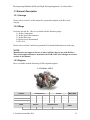


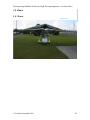
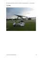
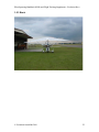
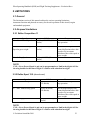


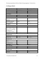
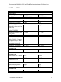
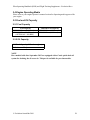


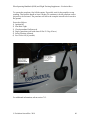


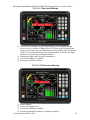


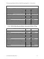
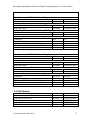

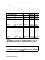

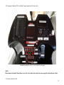

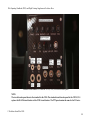

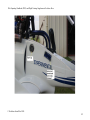

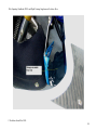
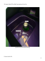

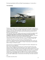
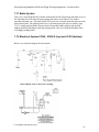
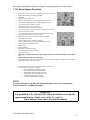
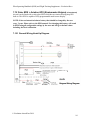
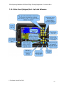

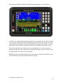


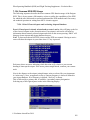
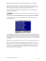
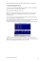
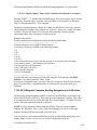
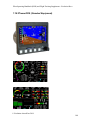


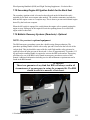


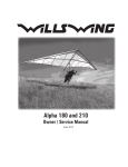


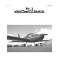
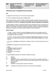
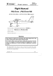
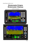
![[FR] Manuel d`instruction FLASHBLACK](http://vs1.manualzilla.com/store/data/006318723_1-6972d77362968624b08eecd697efb0eb-150x150.png)