1
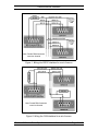
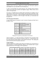
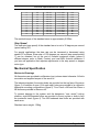
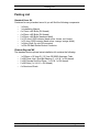
MGL Avionics Autopilot
Servo
Specifications & Installation Manual
Last Update: 20 October 2010
Disclaimer:
MGL Avionics should not be held responsible for errors or omissions in
this document. Usage of all or part of this document for purposes unrelated
to any product of MGL Avionics is prohibited under international copyright
laws.
October 2010
Servo Specifications & Installation Manual
Page 1 of 12
Table of Content
Introduction.............................................................................................................3
Servo Features........................................................................................................3
Communications Interfaces....................................................................................3
RS232 Interface..................................................................................................4
CAN Interface......................................................................................................4
Diagnostic LED....................................................................................................6
Force Measurement ...............................................................................................6
Electrical Specifications and Setup.........................................................................6
Power Supply......................................................................................................6
9 Pin Connector Description...............................................................................7
Torque Settings...................................................................................................7
Step Speed..........................................................................................................8
Mechanical Specification........................................................................................8
Mechanical Drawings..........................................................................................8
Connecting Rod.................................................................................................10
Sheer Safety Screw...........................................................................................11
Packing List...........................................................................................................12
Standard Servo Kit............................................................................................12
Connecting rod kit.............................................................................................12
October 2010
Servo Specifications & Installation Manual
Page 2 of 12
Introduction
Introduction
The MGL Avionics EFIS units (Enigma, Voyager and Odyssey) all contain an
integrated autopilot command system (the “heart” of the autopilot). The only
additional hardware required to provide full autopilot functionality in a MGL EFIS
equipped aircraft is a set of MGL Avionics Servo's - serving as the actuators to
manipulate the elevator, ailerons, etc.
This document outlines the functional specifications and installation instructions
of the servo. The document is aimed at experienced aircraft builders that are
capable of accepting full responsibility for the installation of the servos. The servo
installation should not be performed by some that is not familiar with the potential
dangers of incorrect installation (for example “over center lock-up”).
Three different versions of the servo are available:
– low torque (2.8Nm)
– medium (standard) torque (4.8Nm)
– high torque (6.3Nm).
The low and high torque servos are only manufactured on special request.
Servo Features
The MGL Avionics Servo feature include:
– Precision machined and anodized solid Aluminum housing
– Output shaft runs inside double bearings
– 12 bit output shaft position measurement (sub 0.1 degree resolution)
– Zero contact magnetic output shaft position measurement (no “pots”)
– Force measurement (no additional external subsystems required)
– Low residual torque
– Automatic slip detection
– Digitally adjustable maxim torque setting (4.8Nm – standard servo)
– Robust sub D9 connector simplifying inspection and modular installation
– CAN and RS232 interfaces
– Wide input voltage range (8V – 30V)
– Output arm equipped with safety sheer screw
– 4 + 4 mounting holes to simplify installation (4 side mounting holes)
– 8 holes to fit travel limiting bolts/plate (preventing “over center” lock-up)
– Diagnostic LED indicating communication mode and errors conditions
– 360 degree freedom of movement to simplify installation and setup
Communications Interfaces
Command and feedback messages can be transmitted to and received from the
servo using one of two protocols: CAN (Controller Area Network) or RS232.
Note: Do not try and use both the CAN and RS232 communications interfaces
simultaneously. This will cause conflict and the servo will try and follow both sets
of commands!
October 2010
Servo Specifications & Installation Manual
Page 3 of 12
Communications Interfaces
Enigma EFIS's are not equipped with an internal CAN port and an the internal
RS232 port or a Communications Extender (COEX) is required to connect to the
servo(s).
The Voyager and Odyssey units contain an internal CAN interface. Only the
internal CAN bus can be used to drive the servos.
For more information on setting up the autopilot and communications interfaces
on the EFIS, see the “ Integrated Autopilot User and Installation Manual”
available from http://www.mglavionics.co.za/Docs/Autopilot.pdf.
RS232 Interface
The RS232 communications driver hardware inside the servo allows for multiple
servos to be connected to a single RS232 port. The host (EFIS or PC) will
transmit a single command message to all of the connected servos. A fixed
response delay time is assigned to each servo (depending on the servo function pitch, bank, yaw, etc).
It is recommended that a 33 ohm resistor is fitted in the signal ground return line
to prevent large currents from flowing from the servo to the COEX or the internal
RS232 port. Only one 33 ohm resistor is required - even if multiple servos are
connected to the same RS232 port (see figure 1 below).
The servo RS232 interface is not only used to command the servo, but also to
program the unit and perform diagnostic functions. The servo firmware can be
upgraded using the RS232 interface.
The MGL Avionics servo RS232 communications protocol is open to be general
public and 3rd parties are invited to make use of the servo. For more information
on the RS232 communications protocols refer to the “MGL Avionics Servo
RS232 Protocol” document.
CAN Interface
The CAN bus is a differential signal bus that runs at 250kbps and requires no
ground reference. A number of nodes can be hooked onto a single CAN bus.
Two terminating resistors of 120 ohms should be installed on the CAN bus. If we
assume that no other equipment (engine monitors, AHRS units, etc) are
connected to the CAN bus, fit the two 120 ohm resistors as follow:
– the first resistor is installed close to the EFIS, while...
– the second terminating resistor is installed close to the servo with the
longest communications / wire path to the EFIS.
See figure 2 for details on wiring the servo CAN interface. Servo number “X” is
assumed to be located at the furtherest point from the EFIS.
October 2010
Servo Specifications & Installation Manual
Page 4 of 12
Communications Interfaces
Note: Female DB9 Connectors
seen from Outside
Figure 1: Wiring the RS232 interface for a set of servos
Note: Female DB9 Connectors
seen from Outside
Figure 2: Wiring the CAN interface for a set of servos
October 2010
Servo Specifications & Installation Manual
Page 5 of 12
Communications Interfaces
As is the case with the RS232 protocol, the MGL Avionics servo CAN
communications protocol is open to the general public and 3 rd parties are invited
to make use of the servo (at own risk). For more information on the CAN
communications protocols refer to the “MGL Avionics Servo CAN Protocol”
document.
Diagnostic LED
A single red LED is visible next to the 9 pin connector. This LED is used to
communicate the following information:
– No power connected, or LED failed (LED off)
– Power on but no data/commands being received (solid on, no flashing)
– Power on and RS232 commands being received (slow flashing, 0.5 Hz)
– Power on and CAN commands being received (fast flashing, 2 Hz)
– Power on but error detected (erratic flashing, “short-short-long”)
During power up the unit performs built in testing (BIT) and if any errors are
found (for example a single byte of code is invalid) the unit will not engage /
respond to any communication, but rather signal this error message using an
erratic LED flashing pattern.
Force Measurement
The MGL servo transmits a number that provides an indication of the load on the
servo output shaft. This number is not an absolute or accurately linear
measurement of force or torque. It is however useful as a low frequency
feedback signal to be used to adjust the trim of the aircraft. It provides a good
indication of direction of the load (up or down, left or right) and size of the load
(small, medium, large, very large). The numbers range between -60 and +60.
The force is only measured during the “hold” phase of operation (once the output
arm has reached the target position; not while the servo arm is stepping /
moving). If a torque setting of (approximately) 85% or more is selected, the force
measurement will not be activated. The force measurement can be felt as a slight
vibration on the aircraft controls.
Electrical Specifications and Setup
Power Supply
An input supply voltage of 12V – 15V is recommend. The servo will however run
off 10V – 30V. Do not exceed 34V.
The standard servo draws an average of 0.9A at 13.8V to deliver the maximum
holding torque of 4.8Nm. The maximum stepping torque of 4.8Nm is obtained
drawing an average of 1.71A at 13.8V.
The servos have been installed successfully without the addition of external
capacitors, but depending on the length and thickness of the wires used to
supply the current to the servo, it might be a good idea to fit a large electrolytic
October 2010
Servo Specifications & Installation Manual
Page 6 of 12
Electrical Specifications and Setup
capacitor close to each servo. (2200uF and 10 000uF 35V electrolytic capacitors
are available from your local MGL Avionics distributors.)
In order to accommodate the current required, 18 to 20 gauge wires should be
used for the power wires (positive and negative supply). Thinner wires can be
used for the signal wires.
If the servo is installed onto an bracket that is grounded (for example in an all
metal aircraft), ensure that the area created by the returning ground (thick) power
cable is kept to a minimum – keep the distance between the wire and the metal
construction to a minimum for the full length of the cable up to termination into
the power bus.
9 Pin Connector Description
A single SubD9 cannon connector is used to connect all power and data lines to
the servo. Use a
Pin Number Function/Description
1
Battery Minus / Ground (GND)
2
No Connection (NC)
3
RX RS232
4
TX RS232
5
No Connection (NC)
6,7
Battery Positive / +12 to +28V
8
CAN Low
9
CAN High
Cannon D-9 connector pin description for the Servo
The pin numbers 1, 5, 6 and 9 are written in small print on the connector. Note
that the casing is hard connected to ground as well. Pin 1 is wired directly onto
the casing and the ground planes of the internal electronics. The casing also
serves as a heat sink for the power electronics.
Torque Settings
The true output torque (stepping and holding) and whether force measurement is
being performed vs torque percentage setting for the standard servo is given
below (measured at 13.8V supply, room temperature):
Torque Setting Torque Setting
[-]
[%]
0
0
1
7
2
13
3
20
4
27
October 2010
Torque
Step/Hold [Nm]
4.8 / 2.4
4.8 / 2.4
4.8 / 3.0
4.8 / 3.0
4.8 / 3.7
Current
Step/Hold [A]
1.71 / 0.25
1.71 / 0.25
1.71 / 0.32
1.71 / 0.32
1.71 / 0.46
Servo Specifications & Installation Manual
Force
Measured?
Yes
Yes
Yes
Yes
Yes
Page 7 of 12
Electrical Specifications and Setup
5
6
7
8
9
10
11
12
13
14
15
33
40
47
53
60
67
73
80
87
93
100
4.8 / 3.7
4.8 / 3.9
4.8 / 3.9
4.8 / 4.1
4.8 / 4.1
4.8 / 4.3
4.8 / 4.3
4.8 / 4.5
4.8 / 4.7
4.8 / 4.8
4.8 / 5.5
1.71 / 0.46
1.71 / 0.52
1.71 / 0.52
1.71 / 0.58
1.71 / 0.58
1.71 / 0.60
1.71 / 0.60
1.71 / 0.66
1.71 / 0.71
1.71 / 0.84
1.60 / 0.98
Yes
Yes
Yes
Yes
Yes
Yes
Yes
Yes
No
No
No
The residual torque of the standard servo is approximately 0.28Nm.
Step Speed
The slew rate (step speed) of the standard servo is set to 35 degrees per second
(speed setting 20).
For special applications the slew rate can be increased or decreased using
special PC software. Slew rates of 100 degrees per second (step speed setting
7) can be obtained, but at the cost of reduced maximum torque (unless a
different stepper motor is fitted). Contact your local MGL Avionics distributor if
you have an application that requires adjustments to the step speed or stepper
motor type.
Mechanical Specification
Mechanical Drawings
All dimensions are provided in millimeters (mm) unless stated otherwise. All bolts
are metric and supplied as part of the servo kit.
The industry standard 4 mounting holes are provided on the top face of the servo
(figure 3). In addition 4 more (2 on each side) holes are provided to be utilized in
alternative mounting configurations (figure 5). Four 10mm x M5 and four 20mm x
M5 bolts are provided in the servo kit.
To prevent damage to the system and the dangerous “over center” lock-up
situation, eight M4 threaded holes are provided to mount a plate or bolts to limit
the maximum travel (figure 4). Two M4 hardened steel bolts are provided with
each servo.
Standard servo weight: 1.38kg
October 2010
Servo Specifications & Installation Manual
Page 8 of 12
Mechanical Specification
Figure 3: Top View
Figure 4: Limiting Travel (section A taken from Top View)
October 2010
Servo Specifications & Installation Manual
Page 9 of 12
Mechanical Specification
Figure 5: Servo Side View
Connecting Rod
As an additional optional extra an installation kit can be ordered from your local
MGL Avionics distributor. One standard metric installation kit contains the
necessary parts to connect one servo to one actuator.
Figure 6: Connecting Rod
The Rod End Pieces have been designed to be compatible with imperial
standard tubes. If longer lengths of tube are required, the supplied tube can be
replaced with a longer length of 0.5” outside diameter (0.402” ID) 6061 T6
Aluminum obtainable from companies like Aircraft Spruce.
October 2010
Servo Specifications & Installation Manual
Page 10 of 12
Mechanical Specification
Sheer Safety Screw
A mild steel screw is just to prevent the output arm from rotating relative to the
output shaft. The screw has been selected to fail gracefully when 12Nm of torque
is applied to the output arm. Do not replace the screw with another type of screw.
Output Arm kept from rotating
relative to Output Shaft and Collar
due to Sheer Screw (in place)
October 2010
Output Shaft and Collar with Output
Arm removed exposing 4 sets of
thread for the Sheer Screw
Servo Specifications & Installation Manual
Page 11 of 12
Packing List
Packing List
Standard Servo Kit
Contained in every standard servo kit you will find the following components:
–
–
–
–
–
–
–
–
–
1 x Servo
1 x Installation Manual
4 x 10mm x M5 Bolts (RH thread)
4 x 20mm x M5 Bolts (RH thread)
2 x 25mm x M4 Bolts (hardened steel)
2 x 120 ohm 0.25W resistor (band colors: brown, red, brown)
1 x 33 ohm 0.25W resistor (band colors: orange, orange, black)
1 x Nylon Shell (for sub D9 connector)
1 x Sub D9 Male Solder Bucket Connector
Connecting rod kit
The standard metric optional extra installation kit contains the following:
–
–
–
–
–
1 x 300mm x 10.3mm ID / 12.7mm OD 6063 Aluminum Tube
2 x M5 Rose Joint / End Bolt Bearing (1 x LH & 1 x RH thread)
2 x M5 Female Rod End Piece (1 x LH & 1 x RH thread)
2 x M5 Nuts (1 x LH & 1 x RH thread)
4 x Aluminum Rivets
October 2010
Servo Specifications & Installation Manual
Page 12 of 12


![sf-list [s]](http://vs1.manualzilla.com/store/data/005727021_1-5e70d84b679a2d9887789b982f459474-150x150.png)