1
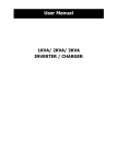
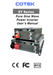
Dual Propulsion Endless Pool
Supplemental Guide
Page 1 of 12
Parts List
Dual Propulsion Pool Internals Kit (supplied by EPI)
Qty
Description
Qty
Description
2
Propulsion Housing (1 Left, “DBL” & 1 Right, “DBR”)
2
Front Base Face Plate (1 Left, “DL” & 1 Right, “DR”)
2
Power Corner w/ Motor & Propeller
(1 Left, “PCL” & 1 Right, “PCR”)
2
2
Power Wings (1 Left, “PWL” & 1 Right, “PWR”)
2
Front Base Caps (1 Left, “L” & 1 Right, “R”)
__ Middle Side/Rear Channel Inserts (depending on
pool length)
4 PVC Shroud Brackets (2 long & 2 short)
1
2
Center Cap (DC)
Side Front Return Channel Caps
(1 Left, “DELB” & 1 Right, “DERB”)
Side Rear Return Channel Caps (DEBSSF)
ABS Side Return Channel Vertical Walls
(1 Left, “DELB” & 1 Right, “DERB”)
Side Bench Supports (number depends on pool size) DESS
Intermediate Side Supports (number depends on pool size)
DEIS
Side Suction Equalizers
2
Rear Suction Equalizers
2
Side Support Beam
2
2
2
__
__
4
Stainless Steel Intake Grill
2 Rear Base Cap
(1 Left, “DRL” & 1 Right, “DRR”)
Rear Corner Turning Vane
2
Shrouds
1
Hardware Pack including:
(8) 1” Liquid Tight Fittings
(4) 1-1/2” Thru-Wall Fittings
(4) 1-1/2” Male Slip x 1” FPT Bushing Reducer
(4) 1” PVC Locknuts for liquid tight fittings
(1) 11/64” Drill Bit
(1) Cover Strip Kit (Includes 200 1” screws &
8 cover strips, 2 labeled "L" & "R")
Tool Required (supplied by others)
#2 Phillips Head Screwdriver
Cordless Drill
Additional Considerations
If an optional hydraulic treadmill has been purchased, then read that Supplemental Guide prior to installing
either product as the treadmill will affect the installation of the Dual Propulsion Pool components.
Prior to installing the internal components of this system, inspect the seams of the liner to ensure that they are
sealed properly. In the unlikely event that a seam is compromised, contact Customer Service (800-910-2714
in the US or 0800 520 0196 in the UK) to receive a new liner.
Installation Instructions
Thru-Wall Panel Cutouts
1) Follow the installation instruction for the Endless Pool found in the, “Endless Pool Installation,
Operations, and User’s Manual” up to step 9, “Optional Lights, Jets, and Treadmill.”
2) Holes may have to be drilled into your front panel to accept the submersible hose assemblies. After
the holes have been drilled into the front panel, continue with the installation of your pool through
steps 10 and 11 and up to but not including step 12, “Cast Composite Internal Components.” This
document replaces those instructions.
Endless Pools Inc.
12/08/2010
Dual Propulsion Endless Pool
Supplemental Guide
Page 2 of 12
Front Component Support Assembly
Keep the screws loose until you have started all the screws. You want to focus on the bottom screws first as
they are difficult to work on once the holes are covered with water. If you use a cordless drill, take care not
to over tighten the screws. Be careful to inspect for burs while installing these screws. If a burr occurs,
remove the screw and discard. Extra screws have been provided. The 1/2” screws should only be used to
secure the power corners to the power wings and the power wings to the propulsion housings; otherwise you
could puncture your liner. Use the 1” screws to secure return channels to internal support components.
1) Place each of the power corners into their respective corners at the front of the pool. The propeller
should be facing the front wall.
Front Panel of Pool
Left Power Corner
(PCL)
Tab of Power Corner
(Fig 1)
2) The placement of the power wings is next. The top of the wing will be labeled to indicate its
orientation (PWL=left side & PWR=right side). Remove the screws that hold the top plate of the
power wing in place and remove the top plate. Next, place each of the power wings along the front
wall of the pool. Make sure that the tab of the top of the corner is behind the front vertical face of the
power wing (see Fig 1).
3) Attach the power corner to the power wing (see Fig 2) using the provided scarf plates. There will be
2 scarf plates (a horizontal plate and a vertical plate) attaching the power wing to the power corner
(see Fig 3). IMPORTANT: You must use 1/2” screws provided when attaching the scarf plates or
you will puncture the liner.
Right Power Wing
Top Plate (PWR)
Right Power Corner
(PCR)
Right Power Wing
(PWR)
(Fig 2)
Endless Pools Inc.
12/08/2010
Dual Propulsion Endless Pool
Supplemental Guide
Page 3 of 12
1/2” Machine Screws
Power Wing
Power Corner
Scarf Plate
(Fig 3)
4) Slide the propulsion housing next to the power wing so that the closed off lower portion of the
housing will be facing the center of the pool. Attach the horizontal tab of the housing to the front
and rear of the vertical faces of the power wing with the provided #6 x 3/4” stainless steel screws.
There is 1 screw in the front and 1 screw in the rear.
5) Secure the housing to the power wing using the scarf plates. There will be 2 scarf plates (a horizontal
plate and a vertical plate) attaching the power wing to the propulsion housing. IMPORTANT: You
must use 1/2” screws provided when attaching the scarf plates or you could puncture the liner.
6) Take the bond wire that is coming from the power corner and feed up through the same hole that has
the bond wire from the housing going through. Pull bond wire tight and wrap around the screw next
to the hole. Tighten screw to secure to bond wires (Fig 4).
7) Four liquid tight fittings (2 per propulsion housing) have been provided for the submersible
hydraulic hoses inside the pool. Insert the liquid tight fitting into the holes immediately adjacent to
the propulsion housing (the holes will be labeled “DEP”). Attach the lock nut, securing the liquid
tight fitting to the housing assembly.
Bond Wire Hole
Bond Wire Screw
Liquid Tight Fitting
(Compression Gland)
Low-Pressure Submersible
Hose (Red tape wrapped
around fitting)
(Fig 4)
8) Loosen the compression gland on the liquid tight fittings and push the submersible hoses up through
the fitting. The low-pressure hoses have red tape wrapped around the fitting and should be positioned
closest to the pool wall. Pull the excess hose up and out of the power wing. Be sure not to pull too
tight that you are putting a kink in the hose. Re-tighten the compression gland. Repeat this process
for the other hose (Fig 4). If you have purchased a hydraulic treadmill, then refer to that
Supplemental Guide as that option will affect the order in which you install these components.
Endless Pools Inc.
12/08/2010
Dual Propulsion Endless Pool
Supplemental Guide
Page 4 of 12
9) Reattach the top plate of the power wing.
10) Repeat steps 1-9 for the other side of the pool.
11) Attach the front base faceplates to the front of each housing. These faceplates will be labeled “DL”
for left faceplate and “DR” for the right faceplate (see Fig 5). Start with the hole that is centered
underneath each housing (this will cause the remaining holes to line up). Only install the lower
screws at this tie. The upper screws will be installed at a later step. Use the provided 1” screws to
attach.
12) A side bench support (DESS) will be installed where the faceplates meet between the 2 propulsion
housings (Fig 5). Attach all four screws on the vertical face first. Place the center cap (DC) on and
install the 4 screws on the horizontal face. Then install the four upper screws (between the housings)
on the vertical face of the cap.
Left Propulsion
Housing (DBL)
Side Bench Support
(DESS)
Left Front Base Faceplate
(DL)
Right Propulsion
Housing (DBR)
Right Front Base Faceplate
(DR)
(Fig 5)
Side Return Channel Support Assembly
1) Next, start the assembly of the front side return channels. These parts will be partially assembled
outside the pool and then placed in the pool. Depending on the length of the pool being assembled,
there may be a middle return channel insert between the two longer side return channels. The
support structure for the front side return channel assemblies will be comprised of a series of
intermediate side supports (DEIS), side bench supports (DESS), and interlocking beams. Please refer
to the diagram on the following page for the proper configuration for your pool.
Side Bench Support
(DESS)
Endless Pools Inc.
Intermediate Side Support
(DEIS)
12/08/2010
Dual Propulsion Endless Pool
Supplemental Guide
Page 5 of 12
Endless Pools Inc.
12/08/2010
Dual Propulsion Endless Pool
Supplemental Guide
Page 6 of 12
2) Outside of the pool, position the interlocking beam so that the notches in the beam are facing up.
The end of the beam that has “PC” engraved into it will eventually be attached to the power corner.
Use the provided #6 x 3/4” stainless steel screws to attach the interlocking beam to the intermediate
side supports (DEIS) and the side bench supports (DESS).
3) Then attach the front side return channel vertical walls (DELB & DERB) to these supports with the
provided 1” machine screws (Fig 7). Lift each side support assembly into the pool and rest them
into place. The front edge of the channel vertical wall will be seated firmly against the front base
faceplate. Secure the interlocking beam to the power corner using the provided #6 x 3/4” stainless
steel screws. Secure the channel vertical wall to the power corner using the provided 1” machine
screws.
Side Return Channel
Vertical Wall
(DERB)
(Fig 7)
4) Attaching the stainless steel intake grills along the side of the pool is next. Place the rear corner
turning vane assemblies into their respective corners. The top edge of the corner turning vanes will
be etched with two score marks. Align the edge of the intake grill with its corresponding score mark.
Use the provided hardware to attach the intake grill to the corner turning vane and to the side bench
support. Make sure to use one of the provided narrow cover strips to the cover the end of the intake
grill where it meets side return channel (or where it meets the middle return channel insert) and at the
end of the intake grill where it meets the rear corner turning vane. These cover strips will only be
labeled with a “T”(Fig 8). The wider strips labeled “L” and “R” will be used later in a different
step.
Stainless Steel
Side/Rear Intake Grill
Rear Right Corner
Turning Vane
Rear Right Stainless
Steel Intake Grill
Side Bench Support
(DESS)
Cover Strip
(to be installed on each
intake grill)
Cover Strip
(Fig 8)
Endless Pools Inc.
12/08/2010
Dual Propulsion Endless Pool
Supplemental Guide
Page 7 of 12
Rear Base Support Assembly
1) Once the vertical sides of the return channels have been positioned and secured, the installation of the
stainless steel side/rear intake grills along the rear of the pool will be next. There will always be two
intake grills along the rear of the pool. Depending on the width of the pool selected, there may be a
middle return channel insert. The middle return channel will require additional supports. Refer to
the diagram below for the proper configuration of the supports.
2) Position the intake grill assembly against the rear corner support. Place the rear cover strips over the
end of the intake grill where it meets the corner support. The rear cover strips will be labeled “L”
and “R” (as you are swimming in the pool). Align the holes in the strip and the holes in the intake
grill. Use the provided screws to attach the cover strip and intake grill to the corner turning vane.
Endless Pools Inc.
12/08/2010
Dual Propulsion Endless Pool
Supplemental Guide
Page 8 of 12
Cover Strips
Rear Left Base
Intake Grill
Rear Right Base
Intake Grill
(Fig 9)
Rear Base Shown is of a 13’ Wide Pool
3) At the center of the rear base, secure the stainless steel side/rear intake grill to the side support. Make
sure to use the narrow cover strips to cover the end of the intake grill prior to securing the side
support. If you have a middle return channel insert, then attach the vertical face to the side bench
supports (DESS) and/or intermediate supports (DEIS) as applicable (Refer to the diagram on page 7).
Bond Wire Installation
Installing the bond wires will be the next step. A total of four additional lengths of wire have been
provided, 4 five-foot lengths. Two of the five-foot lengths will connect the stainless steel intake grills at
the rear of the pool to the stainless steel intake grills along the side of the pool. The other 2 five-foot
lengths will connect the intake grills along the side of the pool to the bonding screw on the side bench
support in the middle of the pool.
1) Each stainless steel intake grill has a PVC stiffeners screwed into the back. Loosen the PVC stiffener
top screw closest to the corner on the intake grill along rear of pool. Wrap the bond wire around that
screw and then retighten the screw. Feed the bond wire through the rear corner turning vane
assembly. Loosen the PVC stiffener top screw closest to the turning vane on the intake grill along the
side of the pool. Pull the wire through to minimize the excess and then wrap the wire around the
screw and retighten the screw. Cut any excess wire as needed.
2) On the opposite end of the stainless steel intake grill, loosen the PVC stiffener top screw closest to the
side bench support (DESS). Wrap the bond wire around this screw and then retighten the screw.
There will be a bonding screw attached to the underside of every side bench support. Loosen the
bonding screw on the side bench support (DESS) that was secured to the intake grill along the side of
the pool. Wrap the bond wire from the intake grill to that screw.
3) Attached to the motor mount in each of the power corners, there will be a bonding wire. Pull that
bond wire through the supports back to the side support attached to the intake grill. Wrap this wire
around the same screw that wire from the previous step is attached to. Make sure that the wire from
the motor mount is taut before tightening the screw.
Endless Pools Inc.
12/08/2010
Dual Propulsion Endless Pool
Supplemental Guide
Page 9 of 12
Suction Equalizer Installation
1) The installation of the suction equalizers is next. There are a total of four, two sides and two rear
equalizers. The longer equalizers are used at the side and the shorter equalizers are used at the rear.
The opening along the long wall of the equalizer should be facing into the pool. The end of the side
equalizer that has three openings should be facing the front of the pool. The end of the rear
equalizer that has three openings should be closest to the corner of the pool.
Rear Suction
Equalizer
Rear Base Stainless Steel
Intake Grill
This end should only
have one opening
(Fig 10)
2) Push the side suction equalizer up against the backside of the intake grill and against the side bench
support. Push the rear suction equalizer up against the backside of the intake grill and against the
rear corner support (Fig 10).
Return Channel and Rear Base Cap Installation
1) Place the front return channel cap (DELB & DERB) over the front supports and position the cap so
that the front vertical bend in the cap is seated against front base faceplate. This should cause the
holes in the cap to align with the holes in the front face of the vertical walls of the return channel (Fig
11). Use the provided 1” screws to attach.
Front Return
Channel Cap
(DELB)
Front Base Cap
(not to be installed until step 1 of
“Finishing Detail Installation”)
(Fig 11)
2) If your pool has the middle return channel insert, then the installation of that cap is next. Position the
insert cap in place so that it is seated against the bench cap at the front of the pool. This should cause
the holes in the cap to align with the holes in the front face of the vertical walls of the return channel
Use the provided 1” screws to attach.
Endless Pools Inc.
12/08/2010
Dual Propulsion Endless Pool
Supplemental Guide
Page 10 of 12
3) Next position the rear return channel cap along side of pool over the intake grill and suction
equalizer. The caps should be seated right against the front cap. The underside of the cap will have a
small milled out section. This allows the cap to nest over the top edge of the stainless steel side/rear
intake grill. Align the holes in the end of the cap with the holes in the support structures underneath.
Front edge of return channel cap should be in line with the return channel cap that is next to it. Use
the provided 1” screws to attach. Once the end screws are secured, use the provided 11/64” drill bit
to drill into the suction equalizer through the three holes in the center of the return channel cap along
side of pool. Thread in the provided 1” screws into the holes that were just drilled.
Rear Return Channel Cap
along side of pool
(Fig 12)
4) Position the rear base return channel caps over the intake grill at the rear of the pool, suction
equalizers and the PVC supports underneath. The underside of the cap will have a small milled out
section. This allows the cap to nest over the top edge of the stainless steel side/rear intake grill. The
rear base cap edge resting on the corner turning vane should align with the score mark on the corner
supports. Align the holes in the end of the caps with the holes in the PVC supports underneath. Front
edge of return channel cap should be in line with the return channel cap that is next to it. Use the
provided screws to attach. Once the end screws are secured, use the provided 11/64” drill bit to drill
into the suction equalizer through the four holes on the left or right side of the rear cap, depending
on which side of the pool you are working on. Thread in the provided 1” screws into the holes that
were just drilled.
5) If there is a middle return channel insert, then the installation of that cap is next. Place the insert cap
over its corresponding PVC supports and secure to the supports with the provided 1” screws.
6) Repeat step 3 for the other side at the rear of the pool.
Endless Pools Inc.
12/08/2010
Dual Propulsion Endless Pool
Supplemental Guide
Page 11 of 12
Finishing Detail Installation
1) You can now continue filling the pool. Once the pool has been filled with water up to the top of the
bench, rest each of the front base caps in place. The mitered corner of the cap goes into the corner
of the pool. Place one of the shorter shroud brackets over the 2 holes closest to the sub hoses. Use
the provided 1” screws to attach the bracket to the base. Use the provided 1” screws to finish
securing the top and vertical faces of the front base caps and faceplates (Fig 13).
Center Cap
Shroud
Front Base Cap
Front Base Faceplates
(Fig 13)
2) Remove the propulsion housing lids by removing the six screws (three on each side). Attach the
housings to pool wall with the stainless steel self-drilling screws. Make sure to wrap the housing bond
wire around one of the screws prior to tightening (This is located on right propulsion housing). Put
the lid back on. Attach the longer shroud bracket to the outside of each housing before installing the
screws. Position the rear corner covers over the rear turning vanes and align the holes in the cover
with the holes in the turning vane. Use the provided 1” screws to attach.
Hydraulic Hose Connection
1) There will be four hydraulic hoses protruding from the front base (submersible hoses), two on either
side of the housing. There will be one hose on either side of the housing that will have red tape
wrapped around the fitting. These are the low-pressure hoses. The remaining two hoses are the highpressure hoses.
2) Cut the liner for the four thru wall fittings, using the hole in the panel as your template.
3) Install the thru wall fittings next. If a hydraulic treadmill is being installed, then the thru-wall
connections will be different. Refer to that Supplemental Guide for more information. The higher
hole in the panel is for the high-pressure hose assembly and the low-pressure hose assembly will be
installed in the lower hole. One rubber gasket will be installed between the fitting and the liner, the
second rubber gasket is installed between the liner and the panel on the inside of the pool, and the
cork gasket will be placed over the fitting on the outside of the pool before the thru wall fitting lock
nut is installed. The lock nuts should only be hand tight.
4) If not done so already, glue a 1-1/2” male slip x 1”FPT bushing reducer into the backside of each of
the thru-wall fittings.
5) If not done so already, thread a liquid tight fitting into each of the bushing reducers. Make sure to
use Teflon sealant/tape on the threads of the liquid tight fitting that is being secured to the bushing
reducers.
6) Loosen the compression nut on the liquid tight fitting. Push the hoses into the thru-wall fittings.
Make sure to pull any excess hose out of the pool. The low-pressure hoses should go into the bottom
holes. Once all the hoses are through the fittings, tighten down on the compression nuts. Note: if a
hydraulic treadmill has been chosen, then refer to the section entitled, “Treadmill Hydraulic Hose
Endless Pools Inc.
12/08/2010
Dual Propulsion Endless Pool
Supplemental Guide
Page 12 of 12
Assemblies” in the Dual Elite Hydraulic Treadmill Supplemental Guide for proper hose
configuration.
7) Place each of the shrouds over their corresponding brackets (brackets were installed in steps 1 & 2)
of the section entitled, “Finishing Detail Installation”). Use the provided 1” screws to secure the
shrouds to the brackets.
Hose Connection to the Power Unit
1) Once the submersible hose assemblies have been installed through the pool wall, connect the
hydraulic run hoses between the pool and the power units. Hydraulic adapters will be provided with
the hydraulic run hoses to connect the run hoses to the submersible hoses. The low-pressure hose
(sub hose with red tape wrapped around fitting) will connect to the hydraulic fitting on the fill cap on
the reservoir. The high-pressure hose is connected to the high-pressure manifold (blue box) on the
power unit. Make sure that one pair of high and low pressure hoses from one propulsion housing are
going to one hydraulic power unit.
Electrical Connections 60hz (United States and Countries with similar electrical
requirements)
Two 30amp GFCI power supplies are required for the Dual Propulsion Endless Pool. One of the power
supplies will be used to power one of the hydraulic power units and the Water Quality System. Please
refer to the “Electrical Wiring Connections 60hz” in the Endless Pool Installation, Operations, and
User’s Manual for more specific direction on this situation.
Electrical Connections 50hz (United Kingdom and Countries with similar electrical
requirements)
Three 30amp RCD rated power supplies will be required for the Dual Propulsion Endless Pool. Each
power unit and the Water Quality System will require a dedicated power supply. Please refer to the
“Electrical Wiring Connections 50hz” in the Endless Pool Installation, Operations, and User’s Manual
for more specific direction on this situation.
Endless Pools Inc.
12/08/2010