1
TM
Installation Procedure
The transmitter and receiver will give the best results if
there is line of sight between them. Obstructions will affect
transmissions if the digital signal is corrupted, but
provided the receiver sees the digital signal you will
always get excellent quality results similar to the picture
quality generated by the camera. With digital, it will
always be a good picture or nothing. It is therefore
advisable to mount the transmitter and receiver at an
adequate height to avoid vehicles and people.
If using several transmitters in the same location try
to keep them 1 metre or more apart. Also it is good
practice to fit directional antennas where multiple
pairs are used.
This also applies to the “receivers” try and also keep
them 1 metre apart.
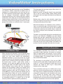
The units have wall mount fixing lugs for internal
installation but for external applications, they must be
installed in a suitable IP rated plastic enclosure. Do not
use metal enclosures. If fitting the Transmitter or Receiver
in an enclosure it is not necessary to make a hole in the
plastic enclosure if it is large enough to house the
complete unit including the antenna. If not, it is not
recommended to have the antenna protruding from a hole
in the top of the enclosure unless a watertight seal can be
made between the antenna and box. It is therefore
recommended to mount the unit so that any hole cut for
the antenna is made in the base of the enclosure and a
good silicon seal made to protect from water/moisture
(figure 3).
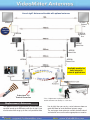
Our Recommended System Design...
figure 3.
In some instances where you can not achieve a clear line
of sight, you may need to fit a more powerful antenna than
those supplied free with the kit. A range of both internal
and external models are available and shown later in this
manual. Whilst different models are available to suit
different installations, please note the same model of
antenna must be fitted at both TX & RX ends.
Once connected, the RX unit will overlay a signal strength
bar on the transmitted picture. This is a useful indicator if
you will be inputting the transmitted signal to
a device other than a monitor as whilst a monitor will
display a signal strength as low as 0.7V p-p, devices such
as DVRs, quads and switchers require a stronger signal of
1V p-p to display an image.
What is line of sight?
This is when the TX and RX can “see” each
other with no obstacles inbetween them.
The TX is mounted in an external weatherproof box and only has to send its signal “line of sight” through air.
There is little to attenuate the signal and good results should be achieved. The external antenna in the receiver
helps “pull-in” the signal from the transmitter.
8