1
HIGH VOLTAGE
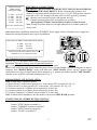
WIRE GAUGE/
DISTANCE CHART
16 AWG:
14 AWG:
12 AWG:
10 AWG:
8 AWG:
Up to 100'
100'-350'
350'-500'
500'-900'
900'-1200'
Over 1200' consult factroy
ELECTRICAL CONNECTIONS:
WARNING: DO NOT APPLY POWER UNTIL TOLD TO DO SO! RISK OF
SHOCK OR INJURY MAY RESULT. Before connecting the operator, use a
voltmeter to determine that the electrical service is 115 VAC. This operator cannot be
connected to 220 volts. Damage will result, which is NOT covered by warranty.
(1.) Be sure power switches at source and operator are OFF.
(2.) Connect incoming power lines and ground wire as follows:
Hot leg (black) to black; Neutral (white) to white; Ground to screw.
Note: Wiring to operator must use watertight materials in accordance with local
electric code.
Note: Master/Slave installation should have SEPARATE power supply wiring. If sharing a power supply line,
obstruction sensing adjustments may require recalibration.
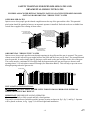
LOW VOLTAGE WIRE GAUGE/ DISTANCE CHART
24 AWG: Up to 150'
20 AWG:
150'-250'
18 AWG:
250'-1500'
Control wiring should be run as twisted pairs. Do not run
control wires in the same conduit as power wires,
telephone wires, or loop detectors leads.
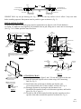
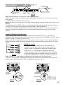
LOCATION OF
RIGHT HAND AND
LEFT HAND HARNESS
CONNECTIONS
LEFT - HAND
P1B
RIGHT - HAND
P1A
LEFT
HAND
P4B
RIGHT
HAND
P4B
LEFT/RIGHT HAND CONVERSION:
Refer to (Fig. 1) to determine hand of operator required for this
HIGH VOLTAGE
installation. This unit is factory setup for right hand operation.
Figure 7
To convert operator to left hand operation, make certain the power
switch is off, and locate 8-pin motor connection plug in center of control board. Squeeze locking tabs to remove
connector from "RIGHT HAND" socket, and insert into "LEFT HAND" socket. Locate 3-position limit
switch harness on edge of control board. Move connector to 3- position pin location marked "LEFT HAND".
Operator is now setup for a left hand installation (See Fig. 7).
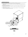
FOR MASTER/SLAVE INSTALLATION:
Note: A single unit is considered Master.
(1.) Place switch #3 on the master operator's P.C. board in the "OFF" position (See Fig. 13).
(2.) Place switch #3 on slave operator's P.C. board in the "ON" position. (See Fig. 13).
(3.) Connect terminal #15 of Master unit to terminal #5 of slave unit.
(4.) Connect terminal #16 of Master unit to terminal #6 of slave unit.
(5.) Connect Terminal #17 of Master unit to terminal #7 of slave unit.
Note: In Master/Slave installation, one unit must be converted to LEFT HAND operation.
CONNECTION OF A THREE BUTTON STATION:
Note: All control contacts must be NORMALLY OPEN.
Connect "STOP" button to terminal #4
Connect "COMMON" button to terminal #5
Connect "OPEN" button to terminal #6
Connect "CLOSE" to terminal #7
-7-
BSG
REV. D