1
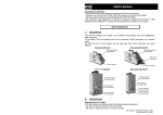
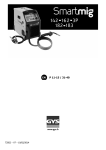
USER'S MANUAL
Declaration of conformity :
These devices have been designed following the European standards :
- Directive Low Tension 73/23 CEE 19/02/1973 (decree nr 95-1081 03/10/1995)
- Directive Electromagnetic Compatibility 89/336 CEE 03/05/1989.
This conformity was established in respect to European standards EN 50199 of 1995
(CEM directive), EN60974-1 of 1998 and amendments A1 of 2000 and A2 of 2003.
IMS WIRE FEEDER WF 324
I/
DESCRIPTION
The IMS wire feeder is suitable on IMS MIG PRO 41/35 MIG welding unit.
To be useful, IMS wire feeder has to be connected to IMS MIG PRO 41/35 via a contact
batch.
IMS WF 324 wire feeder can be used with rolls whose diameters can reach 300mm.
Front panel IMS WF 324
Wire speed setting
potentiometer
Torch connector
Rear panel IMS WF 324
Control connector
for contact batch
Gasl connector
for contact batch
Power connector
for contact batch
II /
PREPARATION
Settings/choice of rollers
IMS wire feeder is delivered with the following original equipment :
IMS WF 324 : double slot roller 0.8/1.0mm for steel
Last update : 05/08/2009 Version : S84
Nomenclature nr 73502
However, the rollers have to be chosen following the diameter and type of the wire to be
used => reverse the slot if needed (see chart here below).
Double slot roller
0.6/0.8mm
0.8/1.0mm
0.8/1.0mm alu
0.9/1.2mm no gas
1.2/1.6mm
1.2/1.6mm alu
Reference
042353
042360
042377
042407
042384
042391
- Select the position of the wire feeder on your MIG,
- Set your MIG as usual (current, 2T, 4T, etc.),
- Then set the wire speed thanks to the wire speed setting potentiometer of the wire
feeder.
IV / OUR ADVICE
- Let the ventilation holes free to let the air coming in and out.
- The maintenance must only be done by a qualified person.
V/
Connection of the wire feeder to the MIG via the contact batch
- Connect the power cable and the control cable of the MIG contact batch at the rear of the
wire feeder. The power cable has to be rotated of 90°.
Installation of the torch
- Connect the torch to the wire feeder.
Installation of the reel
- Open the wire feeder slot,
- Remove the nut from the reel support,
- Set the reel on its support and insure that it is well locked by the pin and put the nut back
in place,
- For a use with steel wire, place the capillar (A),
- For a use with aluminium wire, do not use capillar in the European connection but a
Teflon sheath (special aluminium) that has to come to the moto-wire feeder,
- Set the wire at the entrance of the moto-wire feeder,
- Untight the tighting lever (B),
- Close the panel of the moto-wire feeder,
- Push on the "AVANCE FIL" of the MIG and on the torch trigger (gas closed),
- Slowly tight the tighting lever (B) until the motor starts to drive the wire.
III / USE
SECURITY
Arc welding can be dangerous and can lead to serious injuries, which can be fatal. Protect
yourself and protect the others.
Take precautions against :
- Arc emissions : Protect yourself thanks - Burns : Wear protective or fire-proof
to an electronic welding helmet in clothing (cotton, overalls or jeans).
compliance with EN 175, supply with Work with welder gloves and a fire-proof
filters in compliance with EN 169 or apron.
EN 379.
Protect the others by installing non
- Rain, steam, humidity : Select a clean flammable protection walls, or prevent
environment to use your product the others to not look at the arc and to
(degree of pollution ≤ 3), on the even keep a sufficient distance
place and put the machine at least one - Fire risks : Suppress all flammable
products from the working area. Do not
meter from the part to be welded.
- Electric shock : This unit has to be work near flammable gas.
used on a single-phase power supply, - Smokes : Do not inhale gas or welding
with 3 wires, with neutral connected to smokes, use adapted extractors
the earth. Do not touch the parts under
voltage. Check that the supply system
is well adapted to the unit.
- Falls : Do not carry the unit over the
people or things.
Do not use this unit near people using Pacemaker.
Do not use the unit to defrost tubing.
Handle the gas bottle with care. Indeed, there are risks if the bottle or the bottle valve are
damaged.
VI / ANOMALIES, CAUSES, REMEDIES
(B)
(B)
(A)
Anomalies
During the starting, there is
a spark between the
electrode and the filler
metal stick.
No starting.
No starting.
The wire speed is not
constant.
Causes
There is an accumulation of
filings on the roller of the
moto-wire feeder.
Remedies
Clean the moto-wire feeder
and the rollers with an air
gun.
No gas
No gas
The wire is spinning on the
roller.
The torch is bended, which
breaks the exit of the wire.
Open the gas.
Gas bottle is empty.
Untight the break of the
wire reel.
Check the torch.
Last update : 05/08/2009 Version : S84
Nomenclature nr 73502