1
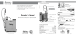
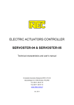
ENel Sp. z o. o. - WROCŁAW
DESIGN AND MANUFACTURE OF POWER
ELECTRONIC DEVICES
INVERTER WELDING MACHINE
ENEL250A
USER MANUAL
DEALER:
1. INTRODUCTION
This manual contains information that will allow to take full advantage of
ENEL250A welding machine operation values and enable its safe use.
Before operating the product, be sure to read this manual.
2. APPLICATION
ENEL250A welding machine is a modern direct current source designed
mainly for welding with coated electrodes (MMA) of all types (ER-, EA-, EB-,
ES-, ...) with diameters from ∅1.6 to ∅5.0. Due to the high open circuit
voltage (90V) and very good welding properties, the device also allows
welding with cellulose coated electrodes which are used, among others, for
pipelines welding.
When equipped with additional TIG welding torch with gas valve placed in
the torch grip, it is possible to weld steel and its alloys and copper and its
alloys using TIG welding (welding with a non-consumable electrode - mostly
tungsten electrode in an inert gas shield, such as argon). The ignition of the
arc is done by scratch.
Due to the small dimensions and weight, and resistance to large voltage
fluctuations, the ENEL250A welder is particularly useful for operation in
difficult field conditions when installing any type of welded structures,
pipelines, tanks, etc.
The device is designed for operation at ambient temperature from -10°C up
to +40°C and relative humidity up to 90% at temperature of + 20°C. You can
not operate the welder in the rain without an additional protection against
water entering the inside of the device.
3. DESCRIPTION
ENEL250AC welding machine is an inverter direct current source operating
in the frequency range above the audio frequency. This current source is
characterised by good dynamics and a smooth and stable arc. It is
lightweight, of small dimensions, resistant to large fluctuations of the mains
voltage. The connecting, control and indicating elements are located on the
front panel. On the rear panel there are: power switch, power cord, fan and
rating plate. Control elements of the welder are shown in Fig. 1. The welding
machine has smooth adjustment of the welding current (knob (1) (Fig. 1))
within the range from 10 to 250A.
2
Figure 1
There are two operation modes available to select with switch (2) (Fig. 1):
1) welding with coated electrodes (MMA) - the switch (2) should indicate
the icon
.
The rectifier is provided with the features:
• HOTSTART - for facilitating the launch of the welding process (at the
moment of arc ignition there occurs a momentary increase of the current
value of about 30% compared to welding current set).
• ANTISTICK - for facilitating electrode unsticking when it adheres to the
works being welded (when the electrode adheres to elements being
welded longer than 3 seconds, the welding current is automatically
switched off, so electrode detaching is not difficult).
2) TIG welding - the switch (2) should indicate the icon
.
HOTSTART and ANTYSTICK functions are off, the arc ignition occurs at
the moment of lifting an electrode (after having touched at the welding start
point).
3
The main switch of welding machine (green) is located on the rear panel backlight of the key indicates that the power cord is connected to the 3
phase mains. After the welding machine is turned on, the green indicator (3)
(Fig. 1) lights up. The welder has a protection against loss of one of supply
phases - in the case of phase loss the indicator (3) (Fig. 1) goes out and the
power module is turned off.
A welder has a thermal protection to protect certain components against
excessive overheating. Activation of this protection is indicated by the lamp
(4) (Fig. 1) shining yellow.
4. TECHNICAL SPECIFICATIONS
Table 1
Item
1
1.
2.
3.
4.
5.
6.
7.
8.
9.
10.
11.
12
.
13.
14.
15.
Parameter
Unit
Value
2
3
4
V
Hz
A
A
A
A
A
kVA
kVA
3x400V
50/60
250
210
10-250
13.0
11.0
8.5
7.0
0.95
90
5x1.5
IP22
C
352
222
262
10.5
EN60974-1
0.92
Power supply (3-phase)
Frequency
Welding current:
P60%
P100%
Current adjustment range
Input current:
P60%
P100%
Output Power:
P60%
P100%
Power factor (250A)
Open Circuit Voltage
Power cable cross-section
Case Enclosure Class
Insulation class
Dimensions: Length
Width
Height
Weight
Compliance with Standard
Electrical Efficiency
4
V
mm2
mm
mm
mm
kg
5. OPTIONAL ACCESSORY
(Can be supplied with rectifier for an extra fee)
1. 3m welding cable 1x35mm2 terminated with an electrode holder K-260.1)
2.
3.
4.
5.
3m welding cable 1x35mm2 terminated with an electric clamp ZBK35.1)
Shoulder strap for carrying the rectifier.
Welding cable with SR26V welding torch of TRAFIMET.
Remote Control module
6. OPERATING INSTRUCTIONS
6.1 CONNECTION TO POWER MAINS
1. ENEL250A welder is manufactured as a protection class I device and
because of users safety should be connected only to the 5-wire electrical
socket provided with the protective (earth) conductor. Electrical supply
circuit should be protected with a time-delayed fuse rated at 10A or
automatic circuit breaker, e.g. S391B10 of FAEL production.
2. After connecting the electrical plug to a power socket, the welding
machine switch located on the rear panel should be lit.
3. The rectifier should be placed in a dry place, so that free inflow and
outflow of cooling air is allowed. It is not permitted to cover the ventilation
openings.
4. Select the operation mode with button (2) (Fig. 1)
5. Preparation the rectifier for MMA welding (with coated electrodes):
connect the welding cable with electrode holder and the cable terminated
with electric clamp to (+) and (-) terminals maintaining polarity in
accordance with the instructions given on the electrode packaging. For
most of the electrodes being used, the welding cable with electrode
holder is connected to the (+) terminal, and the cable with a clamp is
connected to the (-) terminal.
5. Preparation the rectifier for TIG welding:
a) connect the cable with electric clamp to the (+) terminal and TIG welding
torch to the (-) terminal.
b) connect the connector of the welding torch gas hose to the output of
rotameter connected to a gas cylinder.
6.2 OPERATION OF THE RECTIFIER
Prior to welding, ensure that all safety precautions and instructions specified
in section 7.1 have been observed.
1)
Other length cables are available on request.
5
MMA WELDING (WITH COATED ELECTRODES)
1) Connect the welding cable with the electric clamp to the work to be
welded.
2) Turn on the power switch at position ON (ZAŁ). Then the indicator (3)
(Fig. 1) should illuminate indicating that the rectifier is ready for operation.
The cooling fan should turn on immediately.
3) Set the switch (2) in the position marked with MMA welding icon.
4) Fit an electrode in the electrode holder and set welding current suitable
for a specific electrode using the potentiometer (1) (Fig. 1).
5) After the welding is completed, the rectifier should be left connected to
the mains for some time (approx. 3 minutes). This is recommended for
cooling down the heated components.
6) If during welding, the rectifier has been overloaded by exceeding the
permitted duty cycle of 60% at currents given in Table 1, the temperature
limiter can operate. This cuts-off the welding current and lights up the
indicator (4) (Fig. 1). In such case wait until this indicator turns off, and
then you can continue the welding.
7) When the electrode adheres to elements being welded longer than 2-3
seconds, the welding current is automatically switched off, so electrode
detaching is not difficult.
TIG WELDING
1) Connect the welding cable with the electric clamp (connected to the (+)
terminal) to the work to be welded.
2) Fit an appropriate tungsten electrode in the TIG welding torch (connected
to the (-) terminal).
3) Set the power switch in the position ON (ZAŁ).
4) Set the switch (2) (Fig. 1) in the position marked with TIG welding icon.
.
5) Set the proper gas flow using a rotameter on the gas cylinder.
6) The ignition of the arc is done by scratch. Touch the workpiece to be
welded with an electrode (the current doesn't flow while touching, so no
sparking should take place) and lift it immediately - this should initiate
ignition of the arc.
6
7) After the welding is completed, the rectifier should be left connected to
the mains for some time (approx. 3 minutes). This is recommended for
cooling down the heated components.
8) If during welding, the rectifier has been overloaded by exceeding the
permitted duty cycle of 60% at currents given in Table 1, the temperature
limiter can operate. This cuts-off the welding current and lights up the
indicator (4) (Fig. 1). In such case wait until this indicator turns off, and
then you can continue the welding.
7. MAINTENANCE
CAUTION: Before performing any inspection and maintenance unplug
the power cord from the mains.
7.1 ONGOING MAINTENANCE
1) Check the condition of the power cord and insulation of welding cables.
Any damages should be fixed immediately.
2) Ensure that welding cables connections, the electric clamp and isolated
jaws of the welding holder are operational. Any worn or damaged parts
should be replaced.
7.2 PERIODIC MAINTENANCE
Depending on the operating conditions of rectifier but not less frequently than
once every three months, proceed with the following:
1) remove any dust from the internal and external parts using a soft brush
and a vacuum cleaner or compressed air under pressure of ca. 3bar.
2) check the condition and electrical connections, including cables
connected to the protective terminal. All connections should be correct.
3) check if all bolts are firmly tightened.
7
8. REPAIRS
Any repairs may be performed ONLY by persons authorized and trained by
the manufacturer.
9. DANGERS DURING WELDING
Prior to welding, authorized persons should thoroughly read this manual and
strictly observe all given instructions.
Non-compliance with these
instructions may result in, among others, following dangerous
consequences.
9.1 FIRE, EXPLOSION
Observe fire regulations in force at the welding stand. Remove any
flammable materials in the vicinity of the welding stand. Prepare the
appropriate fire-fighting equipment. Keep in mind that due to sparks and
welding arc high temperature, there is a fire hazard even after a certain
period after welding has been completed. Be especially careful when
welding tanks used to store flammable or combustible materials. If
improperly cleaned before welding, may result in explosion.
Argon used for TIG welding is an inert gas and it can remove oxygen from
the atmosphere resulting in suffocation.
Often inspect gas cylinder, pressure regulator and gas hose. All joints should
be tight. Do not connect the gas cylinder directly to the gas hose without a
pressure regulator designed for argon.
Do not use gas cylinders of which content is uncertain. The gas cylinder
should always be secured in an upright position to a wall or a specially
designed cylinder rack. After welding always turn off the cylinder valve.
Handling of gas cylinders must always be done in accordance with the
manufacturer's instructions.
WARNING: Gas cylinder may explode if dropped or fallen over.
8
Figure 2 General electric diagram
9
9.2 BURNS
A welder must be fitted with a suitable non-flammable clothing, welding
gloves, suitable footwear and welding mask. High temperature of the arc,
welding splatter and ultraviolet radiation can cause dangerous injuries.
9.3 HARMFUL FACTORS
Welding process causes emission of vapours harmful to your health.
Welding stand should be provided with efficiently operating ventilation. If the
ventilation is not sufficient, use appropriate protective masks.
Without appropriate gas masks do not weld metals containing lithium,
cadmium, zinc, and beryllium.
9.4 ELECTRIC SHOCK
Do not touch live electrical parts. Do not work in damp places and do not
place the power supply on wet surfaces. Keep your clothing and body dry.
Do not operate the rectifier without housing covers. Inspect the power cords,
plugs and sockets, and the condition of the insulation of all current
conducting wires and welding holders.
Any repairs and inspections must be carried out by qualified and
authorized persons.
10
10. SPARE PARTS LIST
Specification of main components is given in the following table:
Item
1.
2.
3.
4.
5.
6.
7.
8.
9.
10.
11.
12.
13.
14.
15.
16.
17.
18.
Description
Handle
Strap catch
Thermal switch 80°C
Bridge Rectifier
Power transformer
AC transformer 230/2x9V
Operating Mode Switch
IGBT transistor
Control circuit
Output socket
Output choke
Fan protective grille
Potentiometer
Knob
Circuit breaker
Power cord
Cord strain relief
Fan
11
Quantity
1
2
1
3
1
1
1
6
1
2
1
1
1
2
1
1
1
1