1
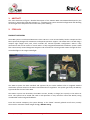
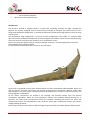
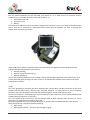
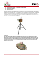
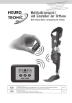
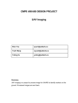
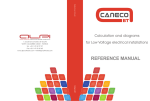
 SYSTEM OVERVIEW
A3R S.r.l. via E. Ortolani 102, 00125, Rome, Italy Tel. +39 06 60513522, Fax. +39 06 96708536, www.a3r.it © A3R, 2011; all rights reserved THIS PAGE IS INTENTIONALLY LEFT BLANK
1. ABSTRACT This short document will give a detailed description of the STRIX‐C MINI UAV SYSTEM developed by the Company in partnership with Alpi Aviation S.r.l., illustrating the system standard configuration and detailing on the single main components that makes the system working. 2. STRIX UAV PRODUCT OVERVIEW: The STRIX system is an Electrical Maneuvers Class UAS Unit. It can be launched by hand or catapult and has been specifically designed for Maneuvers and Special Operation support. The STRIX UAS is carried using a compact light weight back pack, which includes the minimal operable configuration. STRIX is fully autonomous and can be used as a critical node in a fully integrated Networked surveillance system. STRIX flies autonomously toward designated waypoint and controlled on a hand ground station through the free‐
controlled flight or the target mode flight. The STRIX‐C System has been Certified and approved by the Italian Defense after a longhand detailed certification process based on the Italian UAV Airworthiness regulation. The System got finally the Military Type Certificate the 10 of June 2009. The STRIX‐C system was derived by the STRIX‐A version, already in charge (one system) to the Italian Air Force. This System has be tested and used in real operation in many countries around the World, having considerable results and good feedbacks. From the external viewpoint, the system belongs to the “MINI” remotely piloted aircraft class, namely Those with a maximum takeoff weight of 2 kg < MTOW < 20 kg. © A3R, 2011; all rights reserved. Page 3 of 11 The STRIX‐C system, moreover, is completely transportable and can be operated by a single operator due to the fact that it fits into two passably sized backpacks and has a simple management logistic. The system’s aircraft/s can be directly assembled in the operating area in less than 8 minutes and have a mission endurance of 130 minutes each, with potential operational coverage therefore of approx. 6.5 hours of continuous hovering flight if used sequentially. The aircraft, equipped with on board avionics, is controlled by a ground station using a remote control unit which emits flight control signals and records video and telemetry data transmitted by the aircraft to the ground station. The aircraft is launched by a catapult and takes off and land automatically. Through the ground remote control station flight missions can be planned and modified. Moreover, it also controls data acquisition and interaction with the payload by directing its movements, during daytime and nighttime, since the system can also be equipped with a nighttime payload which permits night vision through an IR video camera. Everything necessary for minimum system operability (one aircraft with payload, the catapult and the ground station) can be transported in two dedicated backpacks which neatly house all system components. MAIN FEATURES: The main features of the STRIX‐C UAV can be here summarized: •
•
•
•
•
•
•
•
•
•
•
•
•
One Man Transportable Ready for operation in less than 6 minutes Packaged in less than 6 minutes Automatically launched by a bungee catapult Automatically recovered by automatic flared landing Recovered by automatic parachute landing Emergency Parachute Recovery Day and Night operational capability Continuous mission capability Extremely low noise signature No radar recognized none visible cross section Multi UAV operations (up to 3 UAVs flying simultaneously) Military Type Certified (AERP‐2) SYSTEM STANDARD CONFIGURATION A STRIX system is made of: •
•
•
•
•
3 Aircrafts fully ready to fly 1 Ground Control Station 2 Daytime Payload 1 IR Payload 1 Ground Control Logistic Unit o Launch catapult o Battery charges © A3R, 2011; all rights reserved. Page 4 of 11 •
o External Power Suppliers 1 Spare parts and maintenance kit. UAV Aircraft
The aircraft is defined as equipped when it is fitted with everything necessary for flight, including the payload. The aircraft, equipped with on board avionics including an autopilot and various sensors, has a flying wind sweepback configuration, a streamlined shape and variable percentage thickness from the wing root to the tip. The aerodynamic wing configuration, is as usual in these configurations, auto stable, i.e. naturally stable due to the choice of adequate aerodynamic profiles equipped with “Reflex” and to the accurate positioning of the aircraft centre of gravity with reference to its aerodynamic centre. The use of a particular type of wing tip, known as Winglet, moreover, increases flight performance and lateral stability during all flight phases. An axonometric view of the aircraft is shown in the next Figure. The aircraft is composed of seven main elements which can all be assembled and disassembled, before and after the mission. All these components are primarily manufactured in composite materials, carbon fiber and fiberglass in an epoxy matrix, optimizing material distribution on the basis of structural function, and electromagnetic compatibility. All the avionic components are housed in the fuselage, and therefore distant from the external aerodynamic appendices, which are more exposed to collision and accidental damage during use. In particular, the centre front compartment houses the autopilot, including the sensors, the centre left compartment houses the video/telemetry link, while the centre right compartment houses the system’s salvage/landing parachute. Power supply to the on board avionics and the engine is guaranteed by two lithium polymer battery packs. © A3R, 2011; all rights reserved. Page 5 of 11 These are housed in the two dedicated compartments under the wing situated ventrally in the central body of the fuselage with access through two rear hatches. The user can recharge the batteries by opening the above mentioned hatches, removing the batteries from their housing and recharging them remotely using the battery charging procedure prescribed for this type of batteries as indicated in the available System Use Manual and Maintenance Manual. The power electronics, which provide the power supply for the on board avionics and payload, are housed behind the ventral hatch in the centre of the fuselage. This board, known as the Power Supply & Sensor Board, PSSB, coordinated by its internal central processor, manages the energy from the battery packs “intelligently”, while simultaneously managing, in coordination with the autopilot, the various sensors for monitoring the correct functioning of the engine and other peripherals. The payload’s external vision is assured by the opening of the two hatches in the central area of the fuselage and the payload’s partial running out, thus making hemispherical vision under the aircraft possible. The fuselage is protected by a nose piece in polyurethane foam attached to the central body of the fuselage by means of an elastic system which allows for its deformation thus dissipating part of the energy deriving from any impact. UAV Control Station (UCS)
The UCS is the ground station that handles the generation, elaboration and control of telemetry and video signals (and therefore command and control), from the aircraft. The ground station is powered by rechargeable batteries of the same type equipping the aircraft (Lithium Polymer) and, alternatively, by an external power source. In the case of telemetry data, the UCS retransmits operator or autopilot commands, generated using a special user interface known as CUCS (Core UAV Control Station), to the aircraft. From the architectural point of view the UCS is divided into the following macro components herein briefly described: • CUCS (Core UAV Control Station), which is the flight control interface and mission planner. • CDT (Control Data Terminal), the ground unit which allows data and video link. • BEACON, the ground support module 1) CUCS This unit contains the HCI (Human Control Interface = laptop PC) for flight control and mission planning. The aircraft remote control unit is composed of a Tablet PC with touch screen controls which interfaces with a support structure with mechanical controls, buttons and control stick, the latter are fundamental for mission management. The CUCS is portable and allows the operator to handle missions and any possible emergency correctly and safely. Through the CUCS, the operator can view the acquired video, monitor all flight parameters and manage missions. The unit is wirelessly connected to the CDT, but, if necessary it can be cabled to the CDT to ensure a more reliable connection. The mission control station has its own dedicated battery. If necessary it can be recharged/powered using the PSU provided, by means of the connector situated on the rear of the CUCS, see the maintenance manual. The CUCS is equipped with 1 network connector for the cable connection to the CDT, 2 USB connectors for external hardware i.e. Mouse, USB sticks, etc. The CUCS is equipped with 1 VGA connector which allows the transmission of CUCS screen views to external devices, e.g. auxiliary screens, projectors, etc. The HCI’s screen can rotate and flip into operative position. The operator must rotate the screen view by 180° using the controls on the front left side of t he HCI. © A3R, 2011; all rights reserved. Page 6 of 11 The two backlit keyboards can be extracted and rotated so as to allow access (if necessary and for maintenance) to the tablet PC slots on the sides of the PC, i.e.: • Removable Hard Disk. • SD memory card. • Battery. The CUCS has a dedicated case to facilitate transport and to protect it from rain, wind, sand and humidity and its case can be attached to a dedicated harness (Vest) that the operator can wear to support the weight of the CUCS during missions. The ground station software (command & control) is based on the Windows XP operating system and supports the following activities of the mission: • Mission planning; • Mission control and monitoring; • Mission debriefing; The mission planning software lets you configure the mission through a graphical user interface (HCI) and simple commands given through the touch screen or an alphanumeric keyboard and a mouse touch pad integrated into the HCI. 2) CDT This is the ground unit containing the Rx/Tx telemetry link, the Rx video, the WiFi connection to the CUCS module and the relative data, and the video and WiFi antennas. Its main function is that of receiving telemetry and video data from the aircraft and transmitting them to the CUCS and vice versa. The CDT (next Figure) is connected to the control station by a WiFi connection, which can be substituted by a cable Ethernet connection, if necessary. The unit is powered by an internal 5 cell LIPO battery (with an 8 Ah capacity) and if necessary it can be powered by an external power supply using a PSU. The CDT is equipped with a small metallic dissipater to dissipate the heat emitted by the video receiver. The front of the CDT is equipped with the following: • Main switch • Video signal indicator – presence and strength of signal © A3R, 2011; all rights reserved. Page 7 of 11 •
•
•
Telemetry signal indicator – presence and strength of signal Battery voltage indicator Battery access point To prevent interference due to the proximity of the antennas to the ground during missions, the underside of the CDT has a connection point to permit the CDT to be mounted on a supporting tripod. An Ethernet connector is located on the right corner of the CDT to permit the latter to be connected via cable to the CUCS. All the antennas, telemetry, Wi‐Fi and video, are located on the upper surface of the CDT and can, if necessary, be disconnected by unscrewing them. 3) BEACON This is the ground module that during takeoff and landing (also in remote, i.e. distant from the CDT and the operator) instantly and continuously transmits the programmed landing point’s GPS coordinates and ground level pressure via a radio link identical to that used between the CDT and the aircraft. This allows extremely precise landings in terms of altitude and position, also due to the corrections implemented through the use of the GPS; PAYLOAD
© A3R, 2011; all rights reserved. Page 8 of 11 The aircraft can be equipped with two different and mutually exclusive payloads, a daytime and a nighttime payload, the following are the main characteristics of the two sensors: • Daytime optical system Type of lens optics ¼ CCDTM o Output signal PAL o Resolution in pixels: ≈ 440,000 pixels o Horizontal resolution ≈ 530 TV lines (@ zoom 1X) o Optical zoom 10x o Range: 46° (wide end) to 4.6° (tele end) o Focusing system Automatic o Minimum illumination 1.0 lux • Nighttime optical system o Type of lens optics Uncooled Microbolometer o Resolution in pixels: ≈ 110,500 pixels (384x288) o Visible spectrum 8‐14 μm o Pass: 35 μm The optical cartridge can be rapidly substituted manually, without the aid of tools, by applying a slight pressure over two release flanges. The standard aircraft equipment envisages the pre‐installation of the daytime optical array which is therefore already coupled to the fuselage by means of the pressure fit system. The installation of the nighttime IR payload is accomplished by simply opening the POD protection hatches on the underside of the fuselage, removing the existing system (cartridge) and fitting in the substitute cartridge. The alternative cartridge is transported inside the backpack in a dedicated protective case. As already mentioned, the STRIX‐C’s payload architecture is organized in such a way as to separate the optics movement system, namely the swinging turret, from the optics themselves. The optics are therefore independent elements that can be interchanged (daytime/nighttime) by simply sliding out and repositioning the so‐called “cartridge” containing either the daytime optic or the nighttime optic, which are externally similar except for the front lens. The daytime cartridge, that houses the daytime optic, is shown below with the two “pull tabs” that allow the cartridge to be extracted manually without the use of tools. The nighttime cartridge, equipped with the optic operating in the infrared. MISSION CAPABILITIES
The system permit the following flight mission capabilities: 1. Loiter 2. Flight Director 3. Emergency © A3R, 2011; all rights reserved. Page 9 of 11 4. Video and Telemetry recording 1) LOITER In the loiter modality the aircraft follows a circular flight path at constant altitude and speed. The loiter modality start automatically when the aircraft reach each planned waypoint. During all the mission time the operator can set and edit the following parameters thought the mission planner (CUCS) and management device: • Altitude; • Speed; • Loiter radius; • Loiter versus (clockwise/anticlockwise); • Edit the waypoint/loiter centre position. 2) FLIGTH DIRECTOR In the flight director modality the operator control the aircraft flight thought a small but friendly joystick and can manage the following parameters: • Aircraft altitude; • Aircraft speed; • Aircraft heading. 4) EMERGENCY The system is equipped with two different automatic emergency managements in case of telemetry lost and GPS lost. • Telemetry lost emergency. In every flight phase the autopilot monitors the goodness and robustness of the link radio, assuring, in case of a link lost, a safe and quick re‐entry to the take off point (home). In case of rehabilitation of the radio link, the operator can resume control of the mission. • GPS lost emergency. The stability and control of the aircraft are made always possible by the AHRS (Attitude and Heading Reference System), which provides the aircraft attitude in all flight phases also in absence of GPS signals. 4) VIDEO AND TELEMETRY RECORDING Video recording during the mission can be activated and deactivated on demand by the operator to optimize the memory space available. The CUCS Hard Disk size permit to record more than 100 hours of video streaming and telemetries. MAIN SYSTEM PERFORMANCES
•
•
•
The system can be operated (deployed) in less than 8 minutes and packaged in less than 8 minutes. The main back pack weight is 25 kg: o Nr. 1 ready to operate aircraft o Nr. 1 ground station o Nr. 1 spare optic cartridge o Nr. 1 user manual The ground support equipment that includes the following items weights 16 kg: © A3R, 2011; all rights reserved. Page 10 of 11 •
•
•
•
•
•
•
•
•
•
•
•
•
•
•
•
•
o Nr. 2 LIPO battery chargers; o Nr.1 catapult; o Nr. 2CDT and CUCS power suplliers; o Nr. 1 portable meteo station; The ready to be operated aircraft vehicle weight is 8.6 kg. Minimum speed permitted, 15.0 m/s (55.8 Km/h). Maximum speed permitted, 24 m/s (86.4 Km/h). Optimum cruising speed, 17 m/s (61 Km/h). Rate of climb, 2 m/s. Landing speed, 16 m/s (57.5 Km/h). LOS Range, 12.5 km (7.8 miles) Max Payload Weight, 1.5 kg (3.3 lbs) Max Endurance, 135 min (2.25 hours) Noise emission, at 100 m ground altitude and the standard cruise speed of 17 m/s, less than 40 db. Minimum altitude AGL for operative use 40 m AGL. Maximum altitude AGL for operative use 800 m AGL. Maximum altitude ASL for operative use 2500 m ASL. Rainproof up to a rain intensity ≤ 7mm/hour. Operational wind up to 7 m/s (25 Km/h). Temperature envelope: ‐10 / +50 C°. Humidity envelope: 10 ÷ 95 %. DEVELOPMENT STATUS Fully developed and tested, on selling. Developed in partnership with Alpi Aviation S.r.l. © A3R, 2011; all rights reserved. Page 11 of 11