1
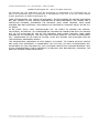
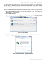
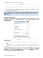
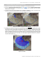
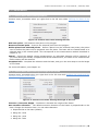
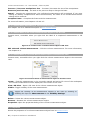
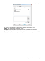
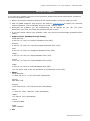
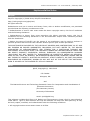
Volume Measurement 1.0 - User Manual | February 2013 Apps VOLUME MEASUREMENT 1.0 - USER MANUAL FEBRUARY 2013 Volume Measurement 1.0 - User Manual | February 2013 ©FARO Technologies Inc., 2013. All rights reserved. For personal use, this publication may be reproduced or transmitted. For commercial use, no part of this publication may be reproduced, or transmitted in any form or by any means without written permission of FARO Technologies Inc. FARO TECHNOLOGIES, INC. MAKES NO WARRANTY, EITHER EXPRESS OR IMPLIED, INCLUDING BUT NOT LIMITED TO ANY IMPLIED WARRANTIES OF MERCHANTABILITY OR FITNESS FOR A PARTICULAR PURPOSE, REGARDING THE FAROARM, FARO LASER TRACKER, FARO LASER SCANNER AND ANY MATERIALS, AND MAKES SUCH MATERIALS AVAILABLE SOLELY ON AN “ASIS” BASIS. IN NO EVENT SHALL FARO TECHNOLOGIES INC. BE LIABLE TO ANYONE FOR SPECIAL, COLLATERAL, INCIDENTAL, OR CONSEQUENTIAL DAMAGES IN CONNECTION WITH OR ARISING OUT OF THE PURCHASE OR USE OF THE FAROARM, FARO LASER TRACKER, FARO LASER SCANNER OR ITS MATERIALS. THE SOLE AND EXCLUSIVE LIABILITY TO FARO TECHNOLOGIES, INC., REGARDLESS OF THE FORM OF ACTION, SHALL NOT EXCEED THE PURCHASE PRICE OF THE MATERIALS DESCRIBED HEREIN. THE INFORMATION CONTAINED IN THIS MANUAL IS SUBJECT TO CHANGE WITHOUT NOTICE AND DOES NOT REPRESENT A COMMITMENT ON THE PART OF FARO TECHNOLOGIES INC. ACCEPTANCE OF THIS DOCUMENT BY THE CUSTOMER CONSTITUTES ACKNOWLEDGMENT THAT IF ANY INCONSISTENCY EXISTS BETWEEN THE ENGLISH AND NON-ENGLISH VERSIONS, THE ENGLISH VERSION TAKES PRECEDENCE. FARO Technologies Inc. Internal Control File Location: X:\CONTROL\RECORDS\05MANUFA\PARTSPEC\7 Software\E1064_Volume_Measurement_1.0_Manual_EN.pdf Volume Measurement 1.0 - User Manual | February 2013 Table of Contents 1. Introduction .............................................................................................................. 1 2. Installing the App ...................................................................................................... 1 3. Licensing the App ...................................................................................................... 1 3.1. Single-User License.............................................................................................. 1 3.2. Network Licensing (Floating License) ...................................................................... 4 4. Measuring the Volume of an Object ............................................................................. 5 4.1. Creating the Base of the Frame ............................................................................. 5 4.1.1. Creating the Base from a Selection of Scan Points ............................................... 6 4.1.2. Creating the Base in an Already Existing Plane .................................................... 8 4.1.3. Creating a Plane and Defining the Base in this Plane ........................................... 10 4.1.4. Using an Area Measurement as the Base of the Frame ........................................ 11 4.2. Defining Height and Extrusion Direction of the Frame .............................................. 12 4.3. Completing the Measurement ............................................................................... 13 4.4. Editing Completed Volume Measurements .............................................................. 14 5. Reference Handbook ................................................................................................. 18 5.1. Toolbar.............................................................................................................. 18 5.2. Options ............................................................................................................. 19 5.3. Context Menus ................................................................................................... 20 5.3.1. Context Menu While Defining the Base .............................................................. 20 5.3.2. Context Menu While Defining the Height of the Frame......................................... 20 5.3.3. Context Menu While Editing a Volume Measurement ........................................... 21 5.3.4. Context Menu of the Volume Measurement Object in the 3D View ........................ 21 5.3.5. Context Menu of a Volume Measurement Object in the Structure View .................. 21 5.4. Properties .......................................................................................................... 21 Technical Support........................................................................................................... i Software License Agreement ........................................................................................... iii Implementation Notes ....................................................................................................v Poly2Tri .....................................................................................................................v Qhull .........................................................................................................................v pugixml .................................................................................................................... vi LGPL......................................................................................................................... vi Trademarks ................................................................................................................ viii Volume Measurement 1.0 - User Manual | February 2013 1. Introduction The Volume Measurement is a helpful add-on for SCENE or SCENE LT that extends the standard measurement functionality by enabling the user to measure volumes of complex objects in the 3D view of scans, workspaces or project point clouds. This manual describes the Volume Measurement, its functions and how you can use it to determine the volume of objects in your scan data. View online tutorials in the Internet at http://tutorial.faroeurope.com to learn more about the use of SCENE and the SCENE apps. The Volume Measurement 1.0 works with version 5.1 of SCENE or SCENE LT. 2. Installing the App 1) Open SCENE or SCENE LT 2) If a previous version of the app is installed, remove this version first with the App Manager (available in SCENE or SCENE LT under Tools Apps). 3) Install the app by doing one of the following: Drag & Drop the app file (.fpp file) into SCENE or SCENE LT. Double click the app file in the Windows Explorer. Use the App Manager (available under Tools Apps) to install the app (see the SCENE or SCENE LT manual for more information). 4) Once installed, you should have this icon in your toolbar: . 3. Licensing the App Once installed, you may fully test the Volume Measurement for 7 days without the need of a software license. After the trial period, the Volume Measurement will be disabled and you need a license to further use the app. There are two licensing options: Single-user license. Network (floating) license Both types of licenses can be locked either to the computer where the app is installed (soft lock) or to a SCENE USB dongle (hard lock). Please note: For licensing, a third party software called Sentinel HASP is used and a driver has to be installed on your system to enable licensing of FARO software products. This driver will automatically be installed during the installation of SCENE, but not with SCENE LT. If the required driver is missing on your system, it will automatically be installed by SCENE LT’s app manager when installing the app. 3.1. Single-User License A single-user license can be locked either to a computer or to a SCENE USB dongle. 1 | Chapter 1: Introduction Volume Measurement 1.0 - User Manual | February 2013 You need a SCENE USB dongle in order to use the second option. A single-user license locked to an USB dongle is not bound to a single computer and adds mobility of the license between multiple computers. The USB dongle can be attached to an USB port on any computer running SCENE or SCENE LT. Once attached, the Volume Measurement has a valid license and can be used as normal. Once you have bought a single-user license of the app you will get a product key which consists of 18 numbers. To validate this key and to activate the license, take the following steps: If you have a SCENE USB dongle and if you want to lock the license of the app to this dongle, attach it to the computer. Start SCENE or SCENE LT. Open the Product Activation dialog with the App Manager by clicking Enter License next to the app name or under Help Licensing (only SCENE). Figure 3-1: App manager The Product Activation dialog will show up. Use the automatic activation method via Internet on tab Automatic Activation. Figure 3-2: Activation dialog – Automatic Activation Chapter 3: Licensing the App | 2 Volume Measurement 1.0 - User Manual | February 2013 Enter your product key and click the Activate button (if a SCENE USB dongle is attached you will now be asked whether you would like to lock the license to the computer or to the USB dongle). SCENE or SCENE LT will now contact FARO’s license server to validate the entered key. Depending on the Internet connection, this process might take up some time. Once the key has been successfully validated, the license will be activated and locked to your computer (or USB dongle). Please note: If your single user license is locked to your computer and if you change your hardware or if you want to use the app on a different computer, you will have to renew the license as it is bound to a system ID. Please contact customer service in that case. If the automatic activation fails: In case the automatic activation fails, please check your Internet connection or enter the product key again and retry. If activation still fails, you may activate the app manually on tab Manual Activation. Figure 3-3: Activation dialog – Manual Activation Enter your product key and click the Send button to create an activation request file (a file with the file extension .ar) which must be sent to FARO (this activation request file does not contain any private data): In case an E-Mail client is properly installed on your system an E-Mail with the activation request file attached will automatically be generated. Just send this E-Mail to the provided address. In case an E-Mail client is not installed on your system, you will be prompted to save the file to your hard disk. Please attach this file to an E-Mail and send it to the provided E-mail address. Once the E-Mail has been sent to FARO you will receive an automatic E-Mail with an activation file (a file with the extension .v2c). Save this file to your hard disk, open it with the Manual Activation dialog under Process Activation File, and then click Activate. Your product should now be activated and have a permanent license. 3 | Chapter 3: Licensing the App Volume Measurement 1.0 - User Manual | February 2013 3.2. Network Licensing (Floating License) If you have bought a network license of the Volume Measurement you will receive a license that is linked to a software product key. Like single-user licenses, you can lock network licenses either to a computer (license server) or, if available, to a SCENE USB dongle. To do this and to activate the license, follow the steps described in chapter 3.1. Network licenses are hosted by a license server computer and will be shared to client computers over the network. If you start the app on any computer in your network it will search the network for available licenses. If one is found, it will be used for the time the app is started. When disabling the app or closing SCENE or SCENE LT, the license will be released again and will be available to other installations in the network. To run a computer as a license server licensing software has to be installed on that computer. This is done automatically with the installation of SCENE. If you do not want to install SCENE on the computer that hosts the network licenses, you have to install this software manually. You may find it on the SCENE DVD or in the installation folder of SCENE. The file name of the setup is “haspdinst.exe”. Run this installer and follow the prompts. To administrate your network licenses on the license server, open http://localhost:1947/ in an Internet browser on this computer to run the Sentinel Admin Control Center. Please read the online help of this software for more information. If your license server hosts network licenses of the Volume Measurement that are locked to the computer (and not to an attached USB dongle) you can detach such a network license and bound it to a client computer for a certain period of time. The license can then be used locally on that computer without the need to be connected to the license server. When the detached license expires, it will automatically be disabled on the client computer and restored to the server. For more information, see the online help of the Sentinel Admin Control Center that can be found on your client computer or on the license server under http://localhost:1947/. For more information on network licensing, please read the SCENE manual. Chapter 3: Licensing the App | 4 Volume Measurement 1.0 - User Manual | February 2013 4. Measuring the Volume of an Object Depending on the complexity of the shape of the object you would like to measure you have two options to determine its volume: To measure an object with complex shape, create a frame (in the form of an extruded polygon) that encloses all the scan points of this object (and as few unwanted scan points as possible). The object’s surface will be reconstructed by creating a triangular mesh from the scan points within this frame. The object’s volume will be determined by measuring the volume between the mesh and the base of the frame. The volume of less complex objects in the form of extruded polygons, for example rooms, can be measured by recreating their shape in the point cloud. To do this, create an extruded polygon or frame that matches the shape of the object. The object’s volume will be determined by simply calculating the volume of this frame. The main focus is on creating the frame in the point cloud, which requires the following steps to be accomplished: 1) Define the (two-dimensional polygonal) base of the frame. See chapter 4.1 for more information. 2) Extrude the base: specify the frame’s height and the extrusion direction. See chapter 4.2 for more information. 3) Finally, to complete the measurement, select between the two above mentioned measuring options and simply calculate the volume of the frame or create a mesh from the scan points in the frame to calculate the volume between the mesh and the frame’s base. See chapter 4.3 for more information. 4) Improving the completed measurement, for example by removing unwanted points from the mesh, might be necessary. See chapter 4.4 for more information. 4.1. Creating the Base of the Frame The Volume Measurement offers different possibilities to create the base of the frame: Create the base from a selection of scan points in the point cloud. From this selection, a planar polygon will be created that matches best the selected points. This polygon will be used as the base of the frame. For more information, see chapter 4.1.1. Select an area in a pre-defined plane (limited or unlimited plane) and use this area as the frame’s base. For more information, see chapter 4.1.2. Create a new plane first, select an area in this plane and use this area as the frame’s base. For more information, see chapter 4.1.3. Use the area of an area measurement that was made with the app Area Measurement as the base of the frame. For more information, see chapter 4.1.4. Select one of these options from the drop-down menu of the Volume Measurement toolbar: Figure 4-1: Volume measurement menu 5 | Chapter 4: Measuring the Volume of an Object Volume Measurement 1.0 - User Manual | February 2013 4.1.1. Creating the Base from a Selection of Scan Points 1) Open the 3D view of a scan, scan folder, workspace or the project point cloud. 2) Click the Volume Measurement icon in the toolbar or select Volume measurement from its drop-down menu. A crosshair cursor in the 3D view indicates that the Volume Measurement is enabled. 3) As known from the polygon selection tool in SCENE or SCENE LT, make a polygonal point selection of the area you would like to use as the base for the frame. Figure 4-2: Creating a polygonal point selection 4) Complete the selection (if there are no intersections) with RETURN or double click on the last selected corner point. When completing, the line will be closed; in other words, the last fixed corner point is connected to the starting corner. The selection comprises all the scan points that are enclosed within the outline. An orthogonal regression plane which matches best the selected scan points will be created and the created polygon will be fitted to this plane. This fitted polygon will be used as the base for the volume measurement. The base will be extruded and, in the next step, you may adjust height and direction of extrusion. Continue with chapter 4.2. Figure 4-3: Frame Chapter 4: Measuring the Volume of an Object | 6 Volume Measurement 1.0 - User Manual | February 2013 The surface of the selected polygon is visualized in transparent blue. If there are scan points in front of the polygon, its surface will not appear as fully closed. While selecting the polygon, the edge between the first and the last added point is drawn as a dashed line. This indicates that this edge will be replaced by two new edges when adding the next corner point. To add the next corner point to a different edge, select this edge with the mouse (it will be drawn as a dashed line), and then add the new point as usual. Figure 4-4: Edge displayed with a dashed line Corner points of the polygonal selection can be moved at any time during the selection of the polygon. Just select a corner point and drag it with the mouse to another position. This point will be moved along the already fitted polygon. Figure 4-5: Moving a point The base can only be created from non-intersecting polygons. If there are intersections, only the outline of the fitted polygon is drawn and intersecting edges will be shown in red. In that case you may delete the last selected corner point(s) (with BACKSPACE) or move corner points by dragging them with the mouse until the intersections are resolved. 7 | Chapter 4: Measuring the Volume of an Object Volume Measurement 1.0 - User Manual | February 2013 Figure 4-6: Intersections Right from the beginning, ensure that the base matches the shape of the object as good as possible and that it encloses as few unwanted scan points as possible. This leads to more precise measurement results and reduces the rework effort of editing the resulting mesh (see chapter 4.4). Available hot keys in this measurement mode are: Backspace Removes the selected corner point from the polygon. ESCAPE Disables the Volume Measurement; unfinished polygonal selections will be removed. Keeping CTRL pressed Temporarily disables point selection, allows navigating in the view in examine mode Keeping SHIFT pressed Temporarily disables point selection, allows navigating in the view in the currently selected navigation mode. W, A, S, D, etc Movement in 3D view as usual. I Defines a plane from the selected scan points, the points used to define the plane will be projected onto the plane. The base will now be created based on a selected area in the created plane. This corresponds to the measurement method described in chapter 4.1.3. RETURN Complete the selection and create the base. 4.1.2. Creating the Base in an Already Existing Plane 1) Open the 3D view of a scan, scan folder, workspace or the project point cloud. 2) Select an already available plane in the structure view or the 3D view. This plane will be highlighted in the view. Chapter 4: Measuring the Volume of an Object | 8 Volume Measurement 1.0 - User Manual | February 2013 Figure 4-7: Selected plane 3) Select Volume Measurement based on selected plane from the drop-down menu of the Volume Measurement toolbar. A crosshair cursor in the 3D view indicates that the Volume Measurement is enabled. 4) Make a (non-intersecting) polygonal selection to define the base by selecting points in the selected plane. These points don’t have to be scan points. As described in chapter 4.1.1, you can change the position of already selected points at any time during the selection by dragging them with the mouse. Figure 4-8: Selected area on a plane 5) Complete the selection and the base with RETURN or double click on the last corner point of the selection. The selected polygon will be extruded and you can now adjust the height and direction of the extrusion. Continue with chapter 4.2. The available hot keys are identical to the hot keys described in chapter 4.1.1. Hot key I has no function in this measuring mode. 9 | Chapter 4: Measuring the Volume of an Object Volume Measurement 1.0 - User Manual | February 2013 4.1.3. Creating a Plane and Defining the Base in this Plane 1) Open the 3D view of a scan, scan folder, workspace or the project point cloud. 2) Select Volume measurement defining plane first from the drop-down menu of the Volume Measurement toolbar. A crosshair cursor in the 3D view indicates that the Volume Measurement is enabled. 3) Make a polygonal point selection in the 3D view to define the plane. Figure 4-9: Points selection to define the plane 4) Create the plane from the selected scan points with Return, I or double click on the last corner point of the selection. The created plane will be added to the Workspace and will be available in the Volumes folder (under Measurements) in the structure view. The corner points selected to define the plane will be kept and projected onto the plane. This selection will then be the starting point for the next step, the creation of the base. Figure 4-10: Plane created from the points selection 5) Continue creating a (non-intersecting) polygonal selection to define the base by moving, removing or adding points in the plane. These points don’t have to be scan points. As Chapter 4: Measuring the Volume of an Object | 10 Volume Measurement 1.0 - User Manual | February 2013 described in chapter 4.1.1, you can change the position of already selected points at any time during the selection by dragging them with the mouse. Figure 4-11: Selected area on the plane 6) Complete the selection and the base with RETURN or double click on the last corner point of the selection. The selected polygon will be extruded and you can now adjust the height and direction of the extrusion. Continue with chapter 4.2. The available hot keys are identical to the hot keys described in chapter 4.1.1 4.1.4. Using an Area Measurement as the Base of the Frame With this option you can create a volume measurement based on the area used for an area measurement that was made with the app Area Measurement. This area will be used as the base for the volume measurement. 1) Select the area measurement that you would like to use as the base for the frame in the structure view or in the 3D view. Figure 4-12: Selected area measurement 11 | Chapter 4: Measuring the Volume of an Object Volume Measurement 1.0 - User Manual | February 2013 2) Select Volume Measurement based on selected area measurement from the dropdown menu of the Volume Measurement toolbar. 3) The area of the selected measurement will be extruded and you can now adjust the height and direction of the extrusion. Continue with chapter 4.2. 4.2. Defining Height and Extrusion Direction of the Frame Once the base is completed you can adjust the height and direction of its extrusion. Increase / Decrease the height of the frame by dragging the red manipulator with the mouse or by pressing CTRL+UP or CTRL+DOWN on your keyboard (keep SHIFT pressed to increase the speed). The current volume of the frame is shown beneath the manipulator. Figure 4-13: Frame The default extrusion direction is perpendicular to the base. You can change this direction when you right click in the view and choose Set extrusion direction in the upcoming context menu. You can select between: Perpendicular to the base (default) Along the x axis Along the y axis Along the z axis Only axes with big enough angles to the normal of the base can be selected. If you want to determine the volume based on a mesh created from the scan points within the frame you should ensure that the frame encloses all the scan points of the object and as few unwanted points as possible. Chapter 4: Measuring the Volume of an Object | 12 Volume Measurement 1.0 - User Manual | February 2013 Available hot keys in this step are: Backspace Return to the previous step (defining the frame’s base) ESCAPE Abort measurement. If you were editing an already completed and saved measurement, the state of the measurement before editing will be restored. CTRL+UP / CTRL+DOWN increase / decrease the height of the frame (hold down SHIFT to increase the speed) + / - on the Numpad Increase / decrease the size of the manipulators RETURN Complete the frame and the measurement 4.3. Completing the Measurement Once the height of the frame has been defined, complete the measurement with RETURN. You will be prompted to select the method of measuring the volume: Figure 4-14: Two options to complete the measurement Volume of mesh: Create a triangular mesh from the scan points within the frame and calculate the volume between the mesh and the base of the frame. Volume of frame: Calculate the volume of the created frame: The volume of the frame will be calculated without taking the scan points within the frame into account. No mesh will be created. This option is useful if you want to calculate the volume of e.g. rooms. 13 | Chapter 4: Measuring the Volume of an Object Volume Measurement 1.0 - User Manual | February 2013 Figure 4-15: Mesh created from the scan points within the frame The measurement result will be shown in the 3D view. Completed measurements will be stored in the workspace. They are available in a sub folder of the Measurements folder. This sub folder is called Volumes. You may apply the surface smoothing filter when creating the mesh. This filter removes outlier points from the mesh that do not belong to the surface of your object. It is only useful if your object has a smooth surface. You can enable or disable this filter in the options of the Volume Measurement. 4.4. Editing Completed Volume Measurements You can edit already completed volume measurements at any time. To edit an already completed volume measurement, select it in the structure view and then select Edit selected volume measurement in the drop-down menu of the volume measurement toolbar or right click the measurement’s label in the 3D view and select Edit selected volume measurement in the upcoming context menu. Chapter 4: Measuring the Volume of an Object | 14 Volume Measurement 1.0 - User Manual | February 2013 Figure 4-16: Context menu of selected mesh in 3D view Once you are in the “edit mode” the colors of the mesh change according to the settings in the options of the Volume Measurement. Figure 4-17: Colored mesh in “Edit mode” Right clicking the mesh brings up a context menu with a range of options: 15 | Chapter 4: Measuring the Volume of an Object Volume Measurement 1.0 - User Manual | February 2013 Figure 4-18: Colored mesh in “Edit mode” Increase resolution (refine the mesh) – The mesh will be refined by decreasing the size and thus increasing the number of the triangles. The finer the mesh, the longer will it take to calculate it. Decrease resolution (coarsen the mesh) – The mesh will be coarsened by increasing the size and thus decreasing the number of the triangles. Restore initial mesh – restore the initial state of the mesh and undo all changes that were made to the mesh during editing. Return to previous step – go to the previous step to change the height of the frame. For more information, see chapter 4.2. Cancel – Cancel editing the volume measurement and quit the “edit mode”. Finish – Finish editing the measurement, save the changes and quit the “edit mode”. Selection - You can also select unwanted points and delete them from the mesh. The selected points and the corresponding triangles will be colored red. Once a selection has been made, you can apply several commands: Clear selection – Clears the available selection without further action. Remove points and smooth selected region – Removes the selected points and triangles from the mesh and closes the resulting hole in the mesh with triangles of greater size. This will smooth the surface of the mesh. Use this, for example, to remove points or triangles that stick out of the surface of the object. Figure 4-19: Removing points from mesh by smoothing the selected region Chapter 4: Measuring the Volume of an Object | 16 Volume Measurement 1.0 - User Manual | February 2013 Remove underlying volume – Removes the selected points or triangles from the mesh without closing the resulting hole in the surface of the mesh. This removes the underlying volume from the measurement. Use this, for example, to remove triangles at the border of the mesh, if you made the base too big. Figure 4-20: Removing points from mesh by removing the underlying volume 17 | Chapter 4: Measuring the Volume of an Object Volume Measurement 1.0 - User Manual | February 2013 5. Reference Handbook 5.1. Toolbar Figure 5-1: Volume measurement toolbar Clicking the icon - Start a volume measurement by creating the base from a selection of scan points. For more information, see chapter 4.1.1. Drop-down menu: Volume measurement – Same effect as clicking the icon (see above). Volume measurement based on selected plane – Start a volume measurement by creating the base in an already available plane. For more information, see chapter 4.1.2. Volume measurement defining plane first – Define a plane in the point cloud first and create the base of the frame in this plane. For more information, see chapter 4.1.3. Volume measurement based on selected area measurement – Use an existing area measurement (created with the app Area Measurement) as the base of the frame. For more information, see chapter 4.1.4. Edit selected volume measurement – Edit an already completed volume measurement. For more information, see chapter 4.4. Options… – Open the options dialog. For more information, see chapter 1.1. Help – Open this manual. Chapter 5: Reference Handbook | 18 Volume Measurement 1.0 - User Manual | February 2013 5.2. Options Access the option of the Volume Measurement from its toolbar. Figure 5-2: Options View Options Show calculated area of mesh – The calculated area of the mesh’s surface will be displayed in the 3D view under the label of the volume measurement. Show number of mesh points – The number of mesh points will be displayed in the 3D view under the label of the volume measurement. Show meshes in front of scan points – The mesh will always be displayed in front of the scan points in the 3D view. Show points removed by surface smoothing – Highlight the points that were removed by the surface smoothing filter during mesh creation (see below for more information). Color of currently edited mesh –Specify the mesh color(s) of the currently edited measurement. If Color Gradient is enabled the mesh will be displayed in gradient colors, starting with Color 1 for points and triangles that are furthermost from the base and transitioning linearly via Color 2 to Color 3 for points and triangles near the base. If Color Gradient is disabled the mesh will be displayed in Color 1. Color of completed meshes - Specify the mesh color(s) of completed measurements. If Color Gradient is enabled the mesh will be displayed in gradient colors, starting with Color 1 for points and triangles that are furthermost from the base and transitioning linearly via Color 2 to Color 3 for points and triangles near the base. If Color Gradient is disabled the mesh will be displayed in Color 1. Enable Same colors as currently edited mesh to use the color settings of the currently edited meshes also for the completed meshes. Filters Enable surface smoothing – Remove outlier points that do not belong to the surface of your object. This filter will be applied when creating the mesh (see chapter 4.3) and is only useful if your object has a smooth surface. You can view the removed points by enabling Show points removed by surface smoothing (see above). Default – Restores the settings to their default values. 19 | Chapter 5: Reference Handbook Volume Measurement 1.0 - User Manual | February 2013 5.3. Context Menus 5.3.1. Context Menu While Defining the Base Context menu, accessible when you right-click in the 3D view while defining the base of the frame: Figure 5-3: Context menu while defining the base Add scan point – Add another scan point to the polygon. Remove selected point – Remove the selected point from the polygon. Define plane from selected points – Define a plane from the selected scan points; the points used to define the plane will be projected onto the plane. The base will be created based on a selected area in the created plane. This corresponds to the measurement method described in chapter 4.1.3. Cancel - Cancel the started volume measurement, an unfinished selection will be removed. If you were editing an already completed and saved measurement, the state of the measurement before editing will be restored. Complete base - Complete the selection and the base, and go to the next step to set the height of the frame. For more information, see chapter 4.1. 5.3.2. Context Menu While Defining the Height of the Frame Context menu, accessible when you right-click in the 3D view while defining the height and the extrusion direction of the frame: Figure 5-4: Context menu while defining the height of the base Increase / Decrease height – Increase or decrease the height of the frame. Set extrusion direction – The default extrusion direction of the frame is perpendicular to the base. Change this direction here. You can select between: Perpendicular to the base (default) Along the x axis Along the y axis Along the z axis Chapter 5: Reference Handbook | 20 Volume Measurement 1.0 - User Manual | February 2013 Increase / Decrease manipulator size – Increase / decrease the size of the manipulator. Return to previous step – Go back to the previous step to change the base. Cancel – Cancels the measurement; the unfinished measurement will be deleted. If you were editing an already completed and saved measurement, the state of the measurement before editing will be restored. Complete frame – Complete the frame and the measurement. For more information, see chapters 4.2 and 4.3. 5.3.3. Context Menu While Editing a Volume Measurement See chapter 4.4 for a detailed description of this context menu. 5.3.4. Context Menu of the Volume Measurement Object in the 3D View Context menu, accessible when you right-click the label of a completed measurement in 3D view: Figure 5-5: Context menu of measurement object in 3D view Edit selected volume measurement – Edit the volume measurement. For more information, see chapter 4.4. 5.3.5. Context Menu of a Volume Measurement Object in the Structure View Context menu, accessible when you right-click the volume measurement object in the structure view: Figure 5-6: Context menu of measurement object in structure view Locate - Find the measurement in the currently opened and active 3D view of the workspace. The volume measurement will be displayed in the center of this view. View 3D View – Open a 3D view of the volume measurement object. Visible –Toggle visibility of the area measurement. Toggle the visibility of all measurement objects in the view by enabling or disabling the layer for Measurements in the Visibility Settings. Delete – Delete the volume measurement object. Rename – Rename the volume measurement object. Properties –Open the properties dialog of the volume measurement object. 5.4. Properties Access the properties of a volume measurement object from its context menu. 21 | Chapter 5: Reference Handbook Volume Measurement 1.0 - User Manual | February 2013 Figure 5-7: Properties This properties dialog is similar to the properties dialog of a documentation object. Position - The position of the center of the volume. Description - Information about the calculated volume. You may edit this information. Hyperlinks – Add hyperlinks to web sites, local or shared documents. For more information, see the properties dialog of the documentation object in the SCENE or SCENE LT manual. Chapter 5: Reference Handbook | 22 Volume Measurement 1.0 - User Manual | February 2013 Technical Support If you have any problem using one of our products, please follow these steps before contacting our Technical Support Team: Be sure to read the relevant sections of the documentation to find the help you need. Visit the FARO Customer Care area on the Web at www.faro.com to search our technical support database. This is available 24 hours a day 7 days a week. Document the problem you are experiencing. Be as specific as you can. The more information you have, the easier the problem will be to solve. If you still cannot resolve your problem, have your device’s Serial Number available before calling. Support Hours (Monday through Friday) North America: 8:00 a.m. to 7:00 p.m. Eastern Standard Time (EST). Europe: 8:00 a.m. to 5:00 p.m. Central European Standard Time (CET). Asia: 8:30 a.m. to 5:30 p.m. Singapore Standard Time (SST). Japan: 9:00 a.m. to 5:00 p.m. Japan Standard Time (JST). China: 8:30 a.m. to 5:30 p.m. China Standard Time (CST). India: 9:30 a.m. to 5:30 p.m. India Standard Time (IST). You can also e-mail or fax any problems or questions 24 hours a day. Phone North America: +1 800 736 2771, +1 407 333 3182 (Worldwide) Mexico: 866-874-1154 Europe: +800 3276 7378, +49 7150 9797-400 (Worldwide) Asia: +1 800 511 1360, +65 6511 1350 (Worldwide) Japan: +81 561 63 1411 (Worldwide) China: +400.677.6826 India: 1800.1028456 Fax Technical Support | i Volume Measurement 1.0 - User Manual | February 2013 North America: +1 407-562-5294 Europe: +800 3276 1737, +49 7150 9797-9400 (Worldwide) Asia: +65 6543 0111 Japan: +81 561 63 1412 China: +86 21 6494 8670 India: +91 11.4646.5660 E-Mail North America: [email protected] Europe: [email protected] Asia: [email protected] Japan: [email protected] China: [email protected] India: [email protected] E-Mails or Faxes sent outside regular working hours usually are answered before 12:00 p.m. the next working day. Should our staff be on other calls, please leave a voice mail message; calls are always returned within 4 hours. Please remember to leave a detailed description of your question and your device’s Serial Number. Do not forget to include your name, fax number, telephone number and extension so we can reach you promptly. ii | Technical Support Volume Measurement 1.0 - User Manual | February 2013 Software License Agreement This Software License Agreement is part of the operating manual for the product and software system which you have purchased from FARO TECHNOLOGIES INC. (collectively, the “Licenser”). By your use of the software you are agreeing to the terms and conditions of this Software License Agreement. Throughout this Software License Agreement, the term “Licensee” means the owner of the System. I. The Licensor hereby grants the Licensee the non exclusive right to use the computer software described in this Operating Manual (the “Software”). The Licensee shall have no right to sell, assign, sub-license, rent or lease the Software to any third party without the Licenser’s prior written consent. II. The Licenser further grants the Licensee the right to make a backup copy of the Software media. The Licensee agrees that it will not decompile, disassemble, reverse engineer, copy, transfer, or otherwise use the Software except as permitted by this Agreement. The Licensee further agrees not to copy any written materials accompanying the Software. III. The Licensee is licensed to use the Software only in the manner described in the Operating Manual. Use of the Software in a manner other than that described in the Operating Manual or use of the Software in conjunction with any non-Licenser product which decompiles or recompiles the Software or in any other way modifies the structure, sequence or function of the Software code, is not an authorized use, and further, such use voids the Licenser’s set forth below. IV. The only warranty with respect to the Software and the accompanying written materials is the warranty, if any, set forth in the Quotation/Purchase Order and Warranty Appendix B pursuant to which the Software was purchased from the Licenser. V. THIS WARRANTY IS IN LIEU OF OTHER WARRANTIES, EXPRESS OR IMPLIED, INCLUDING, BUT NOT LIMITED TO, THE IMPLIED WARRANTIES OF MERCHANTABILITY AND FITNESS FOR A PARTICULAR PURPOSE WITH RESPECT TO THE SOFTWARE AND WRITTEN MATERIALS. IN NO EVENT WILL THE LICENSER BE LIABLE FOR DAMAGES, INCLUDING ANY LOST PROFITS OR OTHER INCIDENTAL OR CONSEQUENTIAL DAMAGES ARISING OUT OF THE USE OR INABILITY TO USE THE SOFTWARE, NOTWITHSTANDING THAT THE LICENSER HAVE BEEN ADVISED OF THE POSSIBILITY OF SUCH DAMAGES, THE LICENSER WILL NOT BE LIABLE FOR ANY SUCH CLAIM BY ANY OTHER PARTY. VI. In the event of any breach by the Licensee of this Agreement, the license granted hereby shall immediately terminate and the Licensee shall return the Software media and all written materials, together with any copy of such media or materials, and the Licensee shall keep no copies of such items. VII. The interpretation of this Agreement shall be governed by the following provisions: a. This Agreement shall be construed pursuant to and governed by the substantive laws of the State of Florida (and any provision of Florida law shall not apply if the law of a state or jurisdiction other than Florida would otherwise apply). b. If any provision of this Agreement is determined by a court of competent jurisdiction to be void and non-enforceable, such determination shall not affect any other provision of this Agreement, and the remaining provisions of this Agreement shall remain in full force and effect. If any provision or term of this Agreement is susceptible to two or more constructions or interpretations, one or more of which would render the provision or term void or nonenforceable, the parties agree that a construction or interpretation which renders the term of provision valid shall be favored. c. This Agreement constitutes the entire Agreement, and supersedes all prior agreements and understandings, oral and written, among the parties to this Agreement with respect to the subject matter hereof. VIII. If a party engages the services of an attorney or any other third party or in any way initiates legal action to enforce its rights under this Agreement, the prevailing party shall be Software License Agreement | iii Volume Measurement 1.0 - User Manual | February 2013 entitled to recover all reasonable costs and expenses (including reasonable attorney’s fees before trial and in appellate proceedings). iv | Software License Agreement Volume Measurement 1.0 - User Manual | February 2013 Implementation Notes Poly2Tri Poly2Tri Copyright (c) 2009-2010, Poly2Tri Contributors http://code.google.com/p/poly2tri/ All rights reserved. Redistribution and use in source and binary forms, with or without modification, are permitted provided that the following conditions are met: * Redistributions of source code must retain the above copyright notice, this list of conditions and the following disclaimer. * Redistributions in binary form must reproduce the above copyright notice, this list of conditions and the following disclaimer in the documentation and/or other materials provided with the distribution. * Neither the name of Poly2Tri nor the names of its contributors may be used to endorse or promote products derived from this software without specific prior written permission. THIS SOFTWARE IS PROVIDED BY THE COPYRIGHT HOLDERS AND CONTRIBUTORS "AS IS" AND ANY EXPRESS OR IMPLIED WARRANTIES, INCLUDING, BUT NOT LIMITED TO, THE IMPLIED WARRANTIES OF MERCHANTABILITY AND FITNESS FOR A PARTICULAR PURPOSE ARE DISCLAIMED. IN NO EVENT SHALL THE COPYRIGHT OWNER OR CONTRIBUTORS BE LIABLE FOR ANY DIRECT, INDIRECT, INCIDENTAL, SPECIAL, EXEMPLARY, OR CONSEQUENTIAL DAMAGES (INCLUDING, BUT NOT LIMITED TO, PROCUREMENT OF SUBSTITUTE GOODS OR SERVICES; LOSS OF USE, DATA, OR PROFITS; OR BUSINESS INTERRUPTION) HOWEVER CAUSED AND ON ANY THEORY OF LIABILITY, WHETHER IN CONTRACT, STRICT LIABILITY, OR TORT (INCLUDING NEGLIGENCE OR OTHERWISE) ARISING IN ANY WAY OUT OF THE USE OF THIS SOFTWARE, EVEN IF ADVISED OF THE POSSIBILITY OF SUCH DAMAGE. Qhull Qhull, Copyright (c) 1993-2012 C.B. Barber Arlington, MA and The National Science and Technology Research Center for Computation and Visualization of Geometric Structures (The Geometry Center) University of Minnesota email: [email protected] This software includes Qhull from C.B. Barber and The Geometry Center. Qhull is copyrighted as noted above. Qhull is free software and may be obtained via http from www.qhull.org. It may be freely copied, modified, and redistributed under the following conditions: 1. All copyright notices must remain intact in all files. Implementation Notes | v Volume Measurement 1.0 - User Manual | February 2013 2. A copy of this text file must be distributed along with any copies of Qhull that you redistribute; this includes copies that you have modified, or copies of programs or other software products that include Qhull. 3. If you modify Qhull, you must include a notice giving the name of the person performing the modification, the date of modification, and the reason for such modification. 4. When distributing modified versions of Qhull, or other software products that include Qhull, you must provide notice that the original source code may be obtained as noted above. 5. There is no warranty or other guarantee of fitness for Qhull, it is provided solely "as is". Bug reports or fixes may be sent to [email protected]; the authors may or may not act on them as they desire. pugixml This software is based on pugixml library (http://pugixml.org). pugixml is Copyright (C) 2006-2012 Arseny Kapoulkine. LGPL Volume Measurement includes the following applications and libraries, which are covered by the LGPL: • Eigen • CppUnit GNU LESSER GENERAL PUBLIC LICENSE Version 3, 29 June 2007 Copyright (C) 2007 Free Software Foundation, Inc. <http://fsf.org/> Everyone is permitted to copy and distribute verbatim copies of this license document, but changing it is not allowed. This version of the GNU Lesser General Public License incorporates the terms and conditions of version 3 of the GNU General Public License, supplemented by the additional permissions listed below. 0. Additional Definitions. As used herein, "this License" refers to version 3 of the GNU Lesser General Public License, and the "GNU GPL" refers to version 3 of the GNU General Public License. "The Library" refers to a covered work governed by this License, other than an Application or a Combined Work as defined below. An "Application" is any work that makes use of an interface provided by the Library, but which is not otherwise based on the Library. Defining a subclass of a class defined by the Library is deemed a mode of using an interface provided by the Library. A "Combined Work" is a work produced by combining or linking an Application with the Library. The particular version of the Library with which the Combined Work was made is also called the "Linked Version". The "Minimal Corresponding Source" for a Combined Work means the Corresponding Source for the Combined Work, excluding any source code for portions of the Combined Work that, considered in isolation, are based on the Application, and not on the Linked Version. vi | Implementation Notes Volume Measurement 1.0 - User Manual | February 2013 The "Corresponding Application Code" for a Combined Work means the object code and/or source code for the Application, including any data and utility pro-grams needed for reproducing the Combined Work from the Application, but ex-cluding the System Libraries of the Combined Work. 1. Exception to Section 3 of the GNU GPL. You may convey a covered work under sections 3 and 4 of this License without being bound by section 3 of the GNU GPL. 2. Conveying Modified Versions. If you modify a copy of the Library, and, in your modifications, a facility refers to a function or data to be supplied by an Application that uses the facility (other than as an argument passed when the facility is invoked), then you may convey a copy of the modified version: a) under this License, provided that you make a good faith effort to ensure that, in the event an Application does not supply the function or data, the facility still operates, and performs whatever part of its purpose remains meaningful, or b) under the GNU GPL, with none of the additional permissions of this License applicable to that copy. 3. Object Code Incorporating Material from Library Header Files. The object code form of an Application may incorporate material from a header file that is part of the Library. You may convey such object code under terms of your choice, provided that, if the incorporated material is not limited to numerical parameters, data structure layouts and accessors, or small macros, inline functions and templates (ten or fewer lines in length), you do both of the following: a) Give prominent notice with each copy of the object code that the Library is used in it and that the Library and its use are covered by this License. b) Accompany the object code with a copy of the GNU GPL and this license document. 4. Combined Works. You may convey a Combined Work under terms of your choice that, taken together, effectively do not restrict modification of the portions of the Library contained in the Combined Work and reverse engineering for debugging such modifications, if you also do each of the following: a) Give prominent notice with each copy of the Combined Work that the Library is used in it and that the Library and its use are covered by this License. b) Accompany the Combined Work with a copy of the GNU GPL and this license document. c) For a Combined Work that displays copyright notices during execution, include the copyright notice for the Library among these notices, as well as a reference directing the user to the copies of the GNU GPL and this license document. d) Do one of the following: 0) Convey the Minimal Corresponding Source under the terms of this License, and the Corresponding Application Code in a form suitable for, and under terms that permit, the user to recombine or relink the Application with a modified version of the Linked Version to produce a modified Combined Work, in the manner specified by section 6 of the GNU GPL for conveying Corresponding Source. Implementation Notes | vii Volume Measurement 1.0 - User Manual | February 2013 1) Use a suitable shared library mechanism for linking with the Library. A suitable mechanism is one that (a) uses at run time a copy of the Library already present on the user's computer system, and (b) will operate properly with a modified version of the Library that is interfacecompatible with the Linked Version. e) Provide Installation Information, but only if you would otherwise be required to provide such information under section 6 of the GNU GPL, and only to the extent that such information is necessary to install and execute a modified version of the Combined Work produced by recombining or relinking the Application with a modified version of the Linked Version. (If you use option 4d0, the Installation Information must accompany the Minimal Corresponding Source and Corresponding Application Code. If you use option 4d1, you must provide the Installation Information in the manner specified by section 6 of the GNU GPL for conveying Corresponding Source.) 5. Combined Libraries. You may place library facilities that are a work based on the Library side by side in a single library together with other library facilities that are not Applications and are not covered by this License, and convey such a combined library under terms of your choice, if you do both of the following: a) Accompany the combined library with a copy of the same work based on the Library, uncombined with any other library facilities, conveyed under the terms of this License. b) Give prominent notice with the combined library that part of it is a work based on the Library, and explaining where to find the accompanying uncombined form of the same work. 6. Revised Versions of the GNU Lesser General Public License. The Free Software Foundation may publish revised and/or new versions of the GNU Lesser General Public License from time to time. Such new versions will be similar in spirit to the present version, but may differ in detail to address new problems or concerns. Each version is given a distinguishing version number. If the Library as you received it specifies that a certain numbered version of the GNU Lesser General Public License "or any later version" applies to it, you have the option of following the terms and conditions either of that published version or of any later version published by the Free Software Foundation. If the Library as you received it does not specify a version number of the GNU Lesser General Public License, you may choose any version of the GNU Lesser General Public License ever published by the Free Software Foundation. If the Library as you received it specifies that a proxy can decide whether future versions of the GNU Lesser General Public License shall apply, that proxy's public statement of acceptance of any version is permanent authorization for you to choose that version for the Library. Written Offer If you, the owner of the scanner, like to get a copy of the source code of LGPL covered parts of the scanner’s firmware, please contact our support team [email protected]. This offer is valid for three years and valid for as long as FARO offers spare parts or customer support for this product model. Trademarks FARO and FARO Laser Scanner Focus 3D are registered trademarks or trademarks of FARO Technologies Inc. All other brand and product names are trademarks or registered trademarks of their respective companies. viii | Trademarks Volume Measurement 1.0 - User Manual | February 2013 Microsoft, Windows, Windows Vista, Windows XP and Windows 7 are either registered trademarks or trademarks of Microsoft Corporation in the United States and/or other countries. Trademarks | ix Volume Measurement 1.0 - User Manual | February 2013 FARO Technologies, Inc. 250 Technology Park Lake Mary, FL 32746 Tel. (800)-736-2771 U.S. / +1 407-333-3182 Worldwide E-Mail: [email protected] FARO Europe GmbH & Co. KG Lingwiesenstrasse 11/2 D-70825 Korntal-Münchingen, Germany Tel: +49 7150/9797-400 (FREECALL +800 3276 7378) Fax: +49 7150/9797-9400 (FREEFAX +800 3276 1737) E-Mail: [email protected] FARO Singapore Pte. Ltd. No. 03 Changi South Street 2 #01-01 Xilin Districentre Building B SINGAPORE 486548 TEL: +65 6511.1350 E-Mail: [email protected] FARO Japan, Inc. 716 Kumada, Nagakute-city, Aichi, 480-1144, Japan Tel: 0120-922-927, 0561-63-1411 FAX:0561-63-1412 E-Mail: [email protected] FARO (Shanghai) Co., Ltd. 1/F, Building No. 2, Juxin Information Technology Park 188 Pingfu Road, Xuhui District Shanghai 200231, China Tel.: 400.677.6826 Email: [email protected] FARO Business Technologies India Pvt. Ltd. E-12, B-1 Extension, Mohan Cooperative Industrial Estate, New Delhi-110044 India Tel.: 1800.1028456 Email: [email protected] x | Trademarks