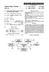
1
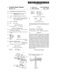
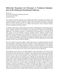
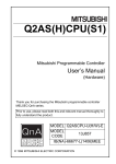
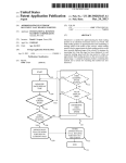
US006949021B2
(12) United States Patent
(10) Patent N0.:
Ichishi et al.
(54)
US 6,949,021 B2
(45) Date of Patent:
VEHICLE AIR CONDITIONER AND
6,659,358 B2 * 12/2003 Kamiya et al. .......... .. 236/49.3
VEHICLE VENTILATION SYSTEM
6,698,262 B2 *
3/2004 Wittwer .......... ..
2001/0039806 A1 * 11/2001
IIIVCIIIOI‘SZ Kumada,
YOShIIlOI‘I Gamagor1
IChIShI, I<ariya
(JP)
Notice:
70/208
Kawai et al. ............... .. 62/229
Tatsumi
(73) Assignee: Denso Corporation, Kariya (JP)
(*)
Sep. 27, 2005
Subject to any disclaimer, the term of this
patent is extended or adjusted under 35
U.S.C. 154(b) by 0 days.
JP
01167551 A
*
JP
5493349
* 8/1993
7/1989
JP
10-278564
* 10/1998
JP
JP
2000442089
2002264635
* 5/2000
9/2002
.......... .. F24F/11/02
* cited by examiner
_
Primary Examiner—Harold Joyce
(21) Appl' NO" 10/779’574
(74) Attorney, Agent, or Firm—Harness, Dickey & Pierce,
(22) Filed:
Feb. 13, 2004
PLC
(65)
Prior Publication Data
(57)
Us 2004/0185764181 56p 23’ 2004
_
(30)
_
_
_
_
sensor is used as an inside
Forelgn Apphcatlon Pnonty Data
Feb. 24, 2003
ABSTRACT
In a vehicle air conditioner, a non-contact temperature
air temperature sensor for
detecting a temperature in a passenger compartment. Based
(JP) ..................................... .. 2003-046124
7
on infrared rays radiated from a predetermined area of the
passenger compartment, the non-contact temperature sensor
(51)
Int- Cl-
(52)
US. Cl. ......................... .. 454/75; 62/186; 165/288;
.....
- - - - - - - - - - - - - - - - - - - - - - - --
B6011 1/00
58
F'1e ld 0 f S earc h ........................ .. 4 5 4/7 5,- 236/91 E ,
236/49.3
236/51, 49.3; 62/186; 165/202, 288, 291
detects a surface temperature
in the predetermined area in
non-contact. Therefore, it is not necessary to bloW air from
the passenger compartment to the inside air temperature
sensor 1n
' or d er to
d etect t h e tem p erature 1n
' t h e p assen g er
compartment. Thus, energy consumption can be reduced
While the temperature in the passenger compartment can be
(56)
References Cited
accurately detected. Accordingly, While the vehicle stops,
U'S' PATENT DOCUMENTS
the vehlcle a1~r cond1t1oner can accurately determme Whether
6,202,934 B1 *
6,397,615 B1 *
6,550,686 B2 *
an cond1t1omng control by an a1r cond1t1onmg umt needs be
3/2001 Kamiya et al. ......... .. 236/91 (3
6/2002 Kawai et al.
4/2003
Kawai et a1. ............ .. 236/493
started While energy consumption can be reduced.
20 Claims, 7 Drawing Sheets
START
(16 OFF)
S100
DISTANCE<D1?
YES
8110
F(t)>F(1;-5)?
YES
5120
BATTERY VOLTAGE>12V?
S130
YES
DETECT TEMPERATURE T(R1)
IN AREA R1
S140
S150
SET “STRONG”?
S160
<=ATTERY VOLTAGE>11.5V"
YES
S170
PERFORM FULL AIR-CONDITIONING
OPERATION FOR A PERIOD (1MIN)
(CALCULATE TAO(Dr) AND TAO(Pa))
|
YES
8162
ERFORM VENTILATI (IN
PERATION FOR A P ERIOI) (1MIN)
U.S. Patent
Sep. 27,2005
Sheet 1 0f 7
US 6,949,021 B2
3A5l8Em
2
w
w
_
u
59
W1L
_5AWE,
my?
,:x22 ,$2, 5mo3m\< onSNdim: m?»R 2mI.E,2N“R
6m"
"
U
53
_2.
1
g
em m
A
\
N
mm
mmE5
:_
___
-a)
n
_
i“
Aliwee:__H?
ON\Sr
m08 .qm0?"
N“;
\_
omr_
H.
w?
n
wsw
n_
P.UE@05 0
U.S. Patent
Sep. 27,2005
Sheet 3 0f 7
FIG. 3
5O 51
FIG. 4
71, 72
21 2O
US 6,949,021 B2
U.S. Patent
Sep. 27,2005
Sheet 4 0f 7
FIG. 5
R2
US 6,949,021 B2
U.S. Patent
Sep. 27,2005
Sheet 5 0f 7
US 6,949,021 B2
FIG. 6
S100
DISTANCE<D1?
$110
N0
8120
BATTERY VOLTAGE>12V?
DETECT TEMPERATURE T(R1)
IN AREA R1
$150
No
SET “STRONG”?
S151 NO
YES
S160
ATTERY VOLTAGE>11.5V'7
SET “WEAK”?
NO
YES/S162
PERFORM VENTILATION
YES
PERFORM FULL AIR-CONDITIONING
OPERATION FOR A PERIOD (1MIN)
(CALCULATE TAO(Dr) AND TAO(Pa))
I
\
END
OPERATION FOR A PERIOD (mm)
U.S. Patent
Sep. 27, 2005
Sheet 6 0f 7
US 6,949,021 B2
FIG. 7
FIG. 8
5wE<a:s3:0
FIG. 9
(FRS) 100 —
sw1
(%)
(REC) 0 -
TAOe
—> HIGH
U.S. Patent
Sep. 27, 2005
US 6,949,021 B2
Sheet 7 0f 7
FIG. 10
S120
NC)
ATTERY VOLTAGE>12.0V?
$130Mq
DETECT TEMPERATURE
TIR(Dr) IN AREA R1
VA
5.0
1*‘
[v] 4.5
4.0
F
34 35
39 40
44 45
TIR(DF) [°C]
END
US 6,949,021 B2
1
2
VEHICLE AIR CONDITIONER AND
VEHICLE VENTILATION SYSTEM
compartment is detected. Thus, energy consumption due to
air bloWing can be prevented While the temperature in the
passenger compartment can be accurately detected.
Accordingly, the vehicle ventilation system can accurately
determine the timing to start ventilating by the ventilating
CROSS REFERENCE TO RELATED
APPLICATION
unit While energy consumption can be reduced.
According to an another aspect of the present invention,
This application is base on Japanese Patent Application
an air conditioner for a vehicle includes an air conditioning
unit Which controls an air condition in a passenger compart
ment While the vehicle stops, a non-contact temperature
sensor Which detects infrared rays radiated from a predeter
mined area of the passenger compartment and detects a
No. 2003-46124 ?led on Feb. 24, 2003, the disclosure of
Which is incorporated herein by reference.
BACKGROUND OF THE INVENTION
surface temperature in the predetermined area in non-contact
1. Field of the Invention
based on the detected infrared rays, and an air-conditioning
The present invention relates to a vehicle air conditioner
determining means Which determines Whether an air condi
and a vehicle ventilation system, Which are operated While 15
tioning control by the air conditioning unit needs to be
a vehicle stops.
started based on the surface temperature detected by the
non-contact temperature sensor. Therefore, the vehicle air
conditioner can accurately determines Whether air condi
2. Description of Related Art
An automatic ventilation system for a vehicle, Which is
used While the vehicle stops, is proposed in JP-A-2000
tioning control by the air conditioning unit needs to be
142089. In this system, a temperature sensor is used in order
to detect a temperature in a passenger compartment. If the
started While energy consumption can be reduced.
Preferably, the ventilation system further includes a res
ervation means Which reserves to perform the ventilation by
detected temperature is higher than a predetermined value,
a bloWer is automatically operated and ventilates the pas
senger compartment.
Generally, a dashboard is heated by sunlight entering into
the passenger compartment, for example, in the daytime in
the ventilating unit in advance. Similarly, the air conditioner
25 includes a reservation means Which reserves to perform the
air conditioning by the air conditioning unit in advance.
Alternatively, the ventilation system or the air conditioner
summer. Thus, if a thermistor inside the dashboard is used
as the temperature sensor, the heated dashboard affects a
temperature detection of the thermistor because an air tem
includes a distance determining means for determining a
distance betWeen a user and the vehicle. In this case, the
perature inside the dashboard increases.
user to the vehicle based on the detected distance betWeen
distance determining means determines an approach of the
In order to detect a temperature in the passenger com
partment correctly, it is possible to bloW air toWard the
temperature sensor by a bloWer Whenever the temperature
sensor detects a temperature. HoWever, in this case, large
energy is consumed because the bloWer is operated.
35
ventilation by the ventilating unit or the air conditioning by
the air conditioning unit needs to be started When the
distance determining means determines the approach of the
Therefore, if the ventilation system ventilates the passenger
compartment for a long time While the vehicle stops, all
energy of a battery may be spent.
user.
40
SUMMARY OF THE INVENTION
In vieW of the foregoing problems, it is an object of the
present invention to provide a vehicle ventilation system
Which reduces energy consumption and accurately deter
mines a timing to start ventilating a passenger compartment
While a vehicle stops.
45
infrared rays. The ventilation determining means determines
Whether a ventilation by the ventilating unit is started based
on the surface temperature detected by the non-contact
surface temperature in the predetermined area including a
seat in the passenger compartment in non-contact.
Therefore, the ventilation or the air conditioning can be
performed to be ?tted to the thermal feeling of the passenger.
According to a further aspect of the present invention, a
control system for controlling a vehicle air conditioner or a
ventilation system While a vehicle is stopped, includes a
determining means that determines Whether an air condi
tioning control by an air conditioning unit or a ventilation
control by a ventilation unit needs to be started based on a
surface temperature detected by a non-contact temperature
sensor. Thus, While the vehicle stops, the control system
control of a passenger compartment While a vehicle stops.
According to an aspect of the present invention, a vehicle
ventilation system includes a ventilating unit, a non-contact
temperature sensor and a ventilation determining means.
While a vehicle stops. The non-contact temperature sensor
detects infrared rays radiated from a predetermined area of
the passenger compartment in non-contact and determines a
surface temperature of the predetermined area based on the
More preferably, in the ventilation system or the air
conditioner, the non-contact temperature sensor detects a
It is another object of the present invention to provide a
vehicle air conditioner Which reduces energy consumption
and accurately determines a timing to start air conditioning
The ventilating unit ventilates a passenger compartment
the user and the vehicle When the detected distance betWeen
the user and the vehicle is smaller than a predetermined
value, and the ventilation determining means or the air
conditioning determining means determines Whether the
accurately determines a timing to start the air conditioning
55
control or the ventilation control of the passenger compart
ment While energy consumption can be effectively reduced.
BRIEF DESCRIPTION OF THE DRAWINGS
Additional objects and advantages of the present inven
tion Will be more readily apparent from the folloWing
detailed description of preferred embodiments When taken
together With the accompanying draWings, in Which:
FIG. 1 is a schematic diagram shoWing an entire system
temperature sensor. Because the non-contact temperature
of a vehicle air conditioner according to a ?rst embodiment
sensor is used in the vehicle ventilation system according to
the present invention. Therefore, it is not necessary to bloW 65 of the present invention;
FIG. 2 is a front vieW shoWing an air-conditioning opera
air from the passenger compartment to the non-contact
tion panel in FIG. 1;
temperature sensor When a temperature in the passenger
US 6,949,021 B2
3
4
FIG. 3 is a front vieW showing an arrangement of inside
air temperature sensors in FIG. 1;
heat exchanger) 42 is provided in the air duct 2 on a
doWnstream air side of the evaporator 41. The heater core 42
FIG. 4 is a perspective vieW shoWing the arrangement of
the inside air temperature sensors in FIG. 1;
FIG. 5 is a perspective vieW shoWing a detection area of
heats air ?oWing therethrough in ?rst and second air pas
5
air passages 11, 12 are separated by a division plate 14.
each of the inside air temperature sensors in a passenger
Further, a Peltier element can be also used as the evaporator
compartment;
41 When the air conditioner is used for a vehicle driven by
electric poWer.
FIG. 6 is a ?oWchart shoWing an air-conditioning opera
tion of an A/C ECU in FIG. 1 in the ?rst embodiment of the
A driver-seat side air mixing door (driver-seat side A/M
door) 15 and a passenger-seat side air mixing door
(passenger-seat side A/M door) 16 are provided on an
present invention;
FIG. 7 is a characteristic graph for determining bloWer
voltage in the ?rst embodiment of the present invention;
FIG. 8 is a characteristic graph for determining an air
outlet mode in the ?rst embodiment of the present invention;
sages 11, 12 by exchanging heat With cooling Water (hot
Water) of the engine for driving. Here, the ?rst and second
15
FIG. 9 is a characteristic graph for determining an open
ing degree of an inside-outside air sWitching door in the ?rst
embodiment of the present invention; and
FIG. 10 is a ?oWchart shoWing an air-conditioning opera
tion of an A/C ECU according to a second embodiment of
upstream air side of the heater core 42. The driver-seat side
A/M door 15 independently controls an air temperature to be
bloWn into the driver-seat side area of the passenger
compartment, and the passenger-seat side A/M door 16
independently controls an air temperature to be bloWn into
the passenger-seat side area of the passenger compartment.
The driver and passenger-seat side A/M doors 15, 16 are
driven by the actuators (e.g., servo motors 17, 18) and
control a temperature of conditioned air bloWing from driver
the present invention.
and passenger-seat side air outlets to the driver and
passenger-seat side areas respectively. More particularly, the
temperature of conditioned air bloWn toWard inner surfaces
DETAILED DESCRIPTION OF THE
PRESENTLY PREFERRED EMBODIMENTS
25
Preferred embodiments of the present invention Will be
described hereinafter With reference to the accompanying
of front Windshield on the driver and passenger-seat sides
are respectively controlled. The driver and passenger-seat
side air outlets Will be explained beloW.
Here, the evaporator 41 according to the ?rst embodiment
of the present invention is a part of a refrigerant cycle 400
draWings.
(First Embodiment)
The ?rst embodiment of the present invention Will be noW
described With reference to FIGS. 1—9.
In the ?rst embodiment of the present invention, an air
cycle 400 includes an electric compressor 410, a condenser
conditioner is typically used for performing an air
conditioning in a passenger compartment of a hybrid vehicle
420, a gas-liquid separator 430, the above-described expan
sion valve 440 and refrigerant piping Which connects the
Which has both an engine and an electric motor for driving.
The vehicle air conditioner is an automatic air conditioner
Which includes an air conditioning unit 1 and an air
and evaporates refrigerant Which is decompressed and
expanded by an expansion valve 440. Further, the refrigerant
35
?oWs into the condenser 420 to be lique?ed and condensed.
Then, the gas-liquid separator 430 separates the lique?ed
conditioning electronic control unit (A/C ECU) 10. The air
conditioning unit 1 can independently control an air tem
perature in a driver-seat side area (e.g., right side area in a
above-described parts circularly. In the refrigerant cycle
400, refrigerant discharged from the electric compressor 410
and condensed refrigerant from the condenser 420 into gas
40
right steering Wheel) and an air temperature in a passenger
seat side area (e.g., left side area in the right steering Wheel).
Here, in the vehicle having the right steering Wheel, the
refrigerant and liquid refrigerant, so that only the liquid
refrigerant ?oWs doWnstream. Then, the expansion valve
440 decompresses and expands the liquid refrigerant from
the gas-liquid separator 430.
In the refrigerant cycle 400, the electric compressor 410
driver-seat side area includes a rear seat on the right side of
45
the vehicle, and the passenger-seat side area includes a rear
compresses and discharges refrigerant. The electric com
seat on the left side of the vehicle. The air conditioning unit
pressor 410 includes an electric motor 460 and an inverter
1 can also independently change an air outlet mode in the
470. The electric motor 460 drives the electric compressor
410. For example, a three-phase induction motor is used as
the electric motor 460. The inverter 470, to Which a battery
driver-seat side area and the passenger-seat side area.
Further, the A/C ECU 10 controls each actuator in the air
conditioning unit 1 so as to control air-conditioning opera
tion of the air conditioning unit 1.
Speci?cally, the air conditioning unit 1 includes an air
duct 2 Which is provided on a front side of the passenger
compartment. An inside-outside air sWitching door 3 and a
55
bloWer 4 are provided on an upstream air side of the air duct
2. The inside-outside air sWitching door 3 is driven by the
actuator (e. g., servo motor 5) and changes an opening degree
B supplies electric poWer, changes a rotation speed of the
electric motor 460 according to a driving frequency calcu
lated by the A/C ECU 10.
Accordingly, the electric compressor 410 changes the
amount of refrigerant discharged from its discharge port to
the condenser 420 by changing a rotation speed of the
electric motor 460. Thus, a cooling capacity of the evapo
rator 41 can be controlled by controlling the amount of
of each of an inside air introduction port 6 and an outside air
refrigerant circulated in the refrigerant cycle 400, that is, the
introduction port 7.
The bloWer 4 is a centrifugal electrical bloWer that is
amount of refrigerant ?oWing into the evaporator 41.
A driver-seat side defroster air outlet 20, a driver-seat side
center-face air outlet 21, a driver-seat side side-face air
outlet 22 and a driver-seat side foot air outlet 23 are opened
driven and rotated by a bloWer motor 9 controlled by a
bloWer driving circuit 8. In the air duct 2, the bloWer 4
generates an air ?oW toWard the passenger compartment.
An evaporator (cooling heat exchanger) 41, Which cools
air ?oWing through the air duct 2, is provided in the air duct
2 doWnstream of the bloWer 4. Further, a heater core (heating
at doWnstream ends of air ducts connected to a doWnstream
65
air side of the ?rst air passage 11 (FIG. 1).
Further, a passenger-seat side defroster air outlet 30, a
passenger-seat side center-face air outlet 31, a passenger
US 6,949,021 B2
5
6
seat side side-face air outlet 32 and a passenger-seat side
foot air outlet 33 are opened at downstream ends of air ducts
connected to a downstream air side of the second air passage
Here, the inside air temperature sensors 71, 72 are
arranged integrally in the dashboard 50 as shown in FIGS.
3 and 4. The driver-seat side inside air temperature sensor 71
detects a temperature in an area R1 (FIG. 5) including a seat
surface on the driver-seat side in non-contact. Further, the
12 (FIG. 1). Here, the driver and passenger-seat side
defroster air outlets 20, 30 are air outlets for blowing
conditioned air (mainly, warm air) to the front windshield at
the right and left sides. The right and left side side-face air
outlets 22, 32 are air outlets for blowing conditioned air
(mainly, warm air) to right and left side windowpanes.
Then, driver and passenger-seat side air-outlet mode
switching doors 24—26, 34—36 are provided in the ?rst and
driver-seat side inside air temperature sensor 71 has a sensor
element which is arranged so that a light receiving surface
points to the area R1. The sensor element of the driver-seat
side inside air temperature sensor 71 outputs an electric
10
second air passage 11, 12. The air outlet mode on each of the
driver and passenger-seat sides can be set independently by
using these doors 24—26, 34—36. Further, these doors 24—26,
34—36 are driven by the actuators (e.g., servo motors 28, 29,
38, 39). Here, the vehicle air conditioner has a face mode, a
15
bi-level mode, a foot mode and a defroster mode, for
eXample, as the air outlet mode on the driver-seat side and
the air outlet mode on the passenger-seat side.
The A/C ECU 10 is supplied with DC power from the
battery B and performs some control operation, such as air
conditioning control in the passenger compartment while the
vehicle drives and air conditioning control in the passenger
compartment while the vehicle stops. The control while the
vehicle stops will be described below. As shown in FIG. 1,
the A/C ECU 10 receives switching signals from operation
signal according to a quantity of infrared rays radiated from
the area R1.
The passenger-seat side inside air temperature sensor 72
detects a temperature in an area R2 (FIG. 5) including a seat
surface on the passenger-seat side in non-contact. Further,
the passenger-seat side inside air temperature sensor 72 has
a sensor element which is arranged so that a light receiving
surface points to the area R2. The sensor element of the
passenger-seat side inside air temperature sensor 72 outputs
an electric signal according to a quantity of infrared rays
radiated from the area R2.
Here, each of the inside air temperature sensors 71, 72 is
a thermo pile type infrared ray sensor. Each of the inside air
temperature sensors 71, 72 includes a temperature sensor
(not shown) for detecting an absolute temperature of each
25
inside air temperature sensor itself. Further, a temperature
sensing element (e.g., thermistor) is used for each of the
switches on an air-conditioning operation pane 151 inte
grally provided in a dashboard 50. Further, the A/C ECU 10
outside air temperature sensor 73, the post-evaporator tem
receives sensor input signals from sensors described below.
perature sensor 74 and the water temperature sensor 75.
Further, the A/C ECU 10 is connected with a keyless ECU
200. The keyless ECU 200 automatically transmits a trans
mitting signal by a radio-wave at certain intervals. An
As shown in FIG. 2, the air-conditioning operation panel
51 has a liquid crystal display 52, an inside-outside air
selecting switch 53, a front defroster switch 54, a rear
defroster (defogger) switch 55, a DUAL switch 56, an air
outlet mode selecting switch 57, an blower air amount
setting switch 58, an A/C switch 59, an AUTO switch 60, an
OFF switch 61, a driver-seat side air temperature setting
switch 62, a passenger-seat side air temperature setting
switch 63 and a fuel consumption improving switch 64, etc.
The air outlet mode selecting switch 57 is used for setting
35
the air outlet mode to any one of the face mode, the bi-level
mode, the foot mode and the defroster mode according to a
40
user manual operation. Further, the air outlet mode selecting
switch 57 is used for setting an air-conditioning state while
the vehicle stops according to a user manual operation. Here,
the air-conditioning state while the vehicle stops is indicated
electronic key 300 transmits a returning signal whenever it
receives the transmitting signal from the keyless ECU 200.
For example, if a user having the electronic key 300
comes to the vehicle to get on, the keyless ECU 200 unlocks
a vehicle door by using a lock device 210 because the
keyless ECU 200 receives the returning signal from the
electronic key 300. Further, if the user having the electronic
key 300 goes away from the vehicle beyond a certain
distance, the electronic key 300 does not receive the trans
mitting signal from the keyless ECU 200 and does not
transmit the returning signal to the keyless ECU 200. That
is, no signal is eXchanged between the keyless ECU 200 and
45
the electronic key 300. If this situation continues for a
62 is used for setting a temperature in the driver-seat side
certain period, the keyless ECU 200 locks the door.
Next, as an eXample of operation according to the ?rst
embodiment of the present invention, an air conditioning
control of the A/C ECU 10 while the vehicle stops will be
area of the passenger compartment to a desired temperature.
described below with reference to FIG. 6.
by a controlling level (“strong”, “weak”, “no setting”) of
air-conditioning in the passenger compartment.
Further, the driver-seat side air temperature setting switch
The A/C ECU 10 performs air conditioning control opera
The passenger-seat side air temperature setting switch 63 is
used for setting a temperature in the passenger-seat side area
of the passenger compartment to a desired temperature.
The A/C ECU 10 is connected with a driver-seat side
inside air temperature sensor 71, a passenger-seat side inside
air temperature sensor 72, an outside air temperature sensor
tion according to a ?owchart in FIG. 6. The air conditioning
control operation starts when an ignition switch IG is
switched off and is repeated at certain intervals (e.g., 250
55
to supply electric power to a driving equipment such as the
engine and the electric motor.
Firstly, the A/C ECU 10 determines whether a distance
73 and a post-evaporator temperature sensor 74 and a water
temperature sensor 75. The driver-seat side inside air tem
perature sensor 71 detects an inside air temperature in the
driver-seat side area, and the passenger-seat side inside air
temperature sensor 72 detects an inside air temperature in
the passenger-seat side area. The outside air temperature
sensor 73 detects an outside air temperature. The post
evaporator temperature sensor 74 detects a temperature of
air blown immediately from the evaporator 41. The water
temperature sensor 75 detects a temperature of engine
cooling water.
msec). The ignition switch IG is used for giving permission
between the user and the vehicle is smaller than a certain
distance D1 (e.g., 50 m) or not (S100). For eXample, the A/C
ECU 10 determines received power of the returning signal
received on the keyless ECU 200 and determines whether
the received power is larger than a predetermined power P.
65
When the received power is larger than the predetermined
power P, the A/C ECU 10 determines that the distance
between the user and the vehicle is smaller than the certain
distance D1, and the determination at step S100 is “YES”.
US 6,949,021 B2
8
7
TAO(Dr)=Kset><TSET(Dr)—KirxTIR(Dr)-Kam><TAM+C (equation 1)
The received power is referred to as F(t) below, and “t”
indicates time (multiples of 250 msec).
TAO(Pa)=Kset><TSET(Pa)—KirxTIR(Pa)-Kam><TAM+C (equation 2)
Next, the A/ C ECU 10 determines Whether the user comes
to the vehicle or not (S110). For example, the A/C ECU 10
compares a received poWer F(t) at the present time and a
received poWer F(t—5) at the time before 5 seconds from the
Where, Kset: temperature setting coefficient (e.g., 7.0)
Kir: infrared ray coef?cient (e.g., 5.1)
Kam: outside air temperature coefficient (e.g., 1.0)
present time. When the received poWer F(t) is larger than the
received poWer F(t—5), the A/C ECU 10 determines that the
C: compensation coefficient (e.g., —45)
user comes to the vehicle, and the determination at step S110
is “YES”.
Next, the A/C ECU 10 determines Whether a terminal
Next, the A/C ECU 10 calculates a bloWer voltage VA,
Which corresponds to air bloWing amount of the bloWer 4
and is applied to the bloWer motor 9, based on TAO(Dr) and
TAO(Pa) calculated above. Firstly, the A/C ECU 10 calcu
voltage (battery voltage) of the battery B is larger than 12 V
or not (S120). That is, the A/C ECU 10 determines Whether
capacity of the battery B is sufficient or not for controlling
an air condition in the passenger compartment While the
vehicle stops, that is, When a vehicle generator does not
lates bloWer voltage VA(Dr) and VA(Pa) in order to calculate
the bloWer voltage VA. Speci?cally, VA(Dr) and VA(Pa) are
15
generate.
voltage VA is calculated by averaging VA(Dr) and VA(Pa).
When the terminal voltage of the battery B is larger than
12 V, the A/ C ECU 10 determines that capacity of the battery
Next, the A/C ECU 10 determines the air outlet mode on
each of the driver and passenger-seat sides based on TAO
B is sufficient. Then, the A/C ECU 10 receives a driver-seat
(Dr), TAO(Pa) and the characteristic graph in FIG. 8.
side temperature (i.e., temperature T(R1) detected by an
When the A/C ECU 10 determines the face mode as the
infrared ray sensor in the driver-seat side area R1) from the
driver-seat side inside air temperature sensor 71 (S130).
Next, in order to determine a timing to start the air condi
tioning control, the A/C ECU 10 determines Whether the
detected temperature T(R1) is larger than a predetermined
temperature 28° C. (S140). When the detected temperature
T(R1) is larger than 28° C., the A/ C ECU 10 determines that
the air conditioning control needs to be started, and the
determination at step S140 is “YES”. That is, the A/C ECU
10 determines that the present time is the timing to start the
air conditioning control. Further, When the detected tem
perature T(R1) is smaller than 28° C., the A/C ECU 10
determines that the air conditioning control should not be
started, and the determination at step S140 is “NO”.
Then, When the determination at step S140 is “YES”, the
A/C ECU 10 determines Whether the air condition setting
While the vehicle stops is set to “strong” by the air outlet
driver-seat side air outlet mode, only the air outlets 21, 22
are opened. When the foot mode is determined as the
driver-seat side air outlet mode, only the air outlet 23 is
25
passenger-seat side air outlet mode, only the air outlets 31,
passenger-seat side air outlet mode, only the air outlet 33 is
opened. When the bi-level mode is determined as the
passenger-seat side air outlet mode, the air outlets 31—33 are
opened.
Next, the A/C ECU 10 averages TAO(Dr) and TAO(Pa)
35
calculated above and obtains an average target air tempera
ture TAOe by using a formula of TAOe=(TAO(Dr)+TAO
(Pa))/2. Then, based on the TAOe and the characteristic
graph in FIG. 9, the A/C ECU 10 determines a target air flow
40
ratio betWeen an inside air amount introduced from the
inside air introduction port 6 and an outside air amount
introduced from the outside air introduction port 7. That is,
the A/C ECU 10 determines a target opening degree SW1
(target operation position) of the inside-outside air sWitching
45
door 3. In FIG. 9, When the target opening degree SW1 is
“100%” (FRS), only outside air is introduced by the inside
outside air sWitching door 3. To the contrary, When the target
opening degree SW1 is “0%” (REC), only inside air is
introduced by the inside-outside air sWitching door 3.
Next, the A/C ECU 10 determines that a driver-seat side
case, the A/C ECU 10 starts and performs a full automatic
A/M door opening degree SW(Dr) (i.e., opening degree of
air-conditioning operation (S170). This full automatic air
conditioning operation continues for a predetermined period
the driver-seat side A/M door 15) is “100%”. Further, the
A/C ECU 10 determines that a passenger-seat side A/M door
(e.g., 1 min).
opening degree SW(Pa) (i.e., opening degree of the
Firstly, in the full automatic air-conditioning operation,
the A/C ECU 10 calculates a driver-seat side target air
opened. When the bi-level mode is determined as the
driver-seat side air outlet mode, the air outlets 21—23 are
opened. Then, When the face mode is determined as the
32 are opened. When the foot mode is determined as the
mode selecting sWitch 57 (S150).
When the air condition setting While the vehicle stops is
“strong”, the A/C ECU 10 determines Whether the terminal
voltage of the battery B is larger than 11.5 V or not (S160).
That is, the A/C ECU 10 determines again Whether the
remaining capacity of the battery B is sufficient or not for
performing the air conditioning control in the passenger
compartment While the vehicle stops. If the terminal voltage
of the battery B is larger than 11.5 V, the A/C ECU 10
determines that the remaining capacity of the battery B is
sufficient for performing the air conditioning control. In this
calculated by using TAO(Dr) and TAO(Pa), respectively
based on the characteristic graph in FIG. 7. Then, the bloWer
55
temperature TAO(Dr) and a passenger-seat side target air
temperature TAO(Pa).
Speci?cally, the TAO(Dr) and TAO(Pa) are calculated
respectively by using a temperature TIR(Dr) detected by the
passenger-seat side A/M door 16) is “100%”.
Next, the A/C ECU 10 outputs a signal corresponding to
the bloWer voltage VA to the bloWer driving circuit 8.
Further, the A/C ECU 10 outputs control signals Which
correspond to the air outlet mode, the SW(Dr), the SW(Pa)
and the target opening degree of the inside-outside air
driver-seat side inside air temperature sensor 71, a tempera
sWitching door 3, to corresponding one of the servo motors
ture TIR(Pa) detected by the passenger-seat side inside air
temperature sensor 72, a temperature TSET(Dr) set by the
5, 17, 18, 28, 29, 38, 39 and the electric motor 460.
driver-seat side air temperature setting sWitch 62, a tem
(motor control signal) for controlling the electric motor 460
In addition, the A/C ECU 10 determines a control value
perature TEST(Pa) set by the passenger-seat side air tem
perature setting sWitch 63 and a temperature TAM detected
by the outside air temperature sensor 73, in accordance With
the folloWing equations 1 and 2.
of the electric compressor 410 based on a temperature
65
detected by the post-evaporator temperature sensor 74. The
amount of refrigerant ?oWing into the evaporator 41 is
changed by controlling the electric motor 460 of the electric
US 6,949,021 B2
10
detected by the driver-seat side inside air temperature sensor
71 is higher than 28° C. That is, the driver-seat side inside
air temperature sensor 71 is used for determining Whether
the ventilation due to the air conditioning unit 1 needs to be
started or not, that is, for determining a timing to start the
compressor 410 based on the determined motor control
value. Thus, the temperature detected by the post-evaporator
temperature sensor 74 can be adjusted to a target tempera
ture.
As described above, the air condition in the passenger
compartment is controlled by the operation of each of the
ventilation operation. Accordingly, the vehicle air condi
electric motor 460 of the electric compressor 410 and the
tioner can accurately determine the timing to start ventila
tion operation due to the air conditioning unit 1 While energy
consumption can be reduced.
servo motors.
Further, When the air condition setting While the vehicle
stops is not “strong” (determination at step S150 is “NO” in
FIG. 6) and is “Weak” (determination at step S161 is
10
(3) The air outlet mode selecting sWitch 57 is provided to
select the controlling level of air condition among the
“YES”), a ventilation operation is performed (S162).
“strong”, the “Weak”, the “no setting” in advance. Therefore,
Further, this ventilation operation continues for a predeter
the air condition in the passenger compartment can be
controlled so as to ?t a passenger’s preference before the
user gets on the vehicle. Especially, if the controlling level
of air condition is set to the “Weak”, it is possible to reserve
mined period (e.g., 1 min).
In this case, the A/C ECU 10 determines the target
opening degree of the inside-outside air sWitching door 3 so
the ventilation operation due to the air conditioning unit 1.
Therefore, it is useful for a user Who prefers only ventilation.
that an inside air amount introduced from the inside air
introduction port 6 is “0%” (full close) and an outside air
amount introduced from the outside air introduction port 7
(4) If a distance betWeen the user and the vehicle is
is “100%” (full open). That is, in the ventilation operation,
smaller than a certain distance D1 and the user comes to the
the inside-outside air sWitching door 3 fully closes the inside
air introduction port 6 and fully opens the outside air
introduction port 7, so that the passenger compartment is
ventilated by outside air. The A/C ECU 10 outputs a control
vehicle, the vehicle air conditioner determines Whether the
air conditioning control by the air conditioning unit 1 should
be started or not. Therefore, the air conditioning control is
degree to the servo motor 5.
performed only When possibility of approach of the user is
high. Accordingly, energy consumption can be minimiZed
because the air conditioning control is performed only When
Further, the A/C ECU 10 outputs a predetermined signal
corresponding to the bloWer voltage VA to the bloWer
it is necessary.
(5) Generally, a passenger is especially sensitive to a
driving circuit 8.
In addition, in the ventilation operation, the A/C ECU 10
temperature of a seat When the passenger sits on the seat. In
determines the bi-level mode as the air outlet mode on each
sensors 71, 72 is the non-contact temperature sensor Which
of the driver and passenger-seat sides and outputs a control
signal corresponding to the determined air outlet mode to the
servo motors 17, 18, 28, 29, 38, 39.
As described above, outside air is introduced in the
passenger compartment and the ventilation operation is
detects the surface temperature of corresponding one of
signal corresponding to the determined target opening
25
the ?rst embodiment, each of the inside air temperature
areas including the driver and passenger seats in non
35
feeling.
performed by operating each of the servo motors 5, 17, 18,
28, 29, 38, 39 and the electric motor 460.
Further, When the air condition setting While the vehicle
stops is not either the “strong” or the “Weak” at step S161,
either the ventilation operation or the air-conditioning opera
tion is not performed in the passenger compartment.
Next, advantages of the vehicle air conditioner according
40
to the ?rst embodiment of the present invention Will be
described beloW.
(1) The non-contact temperature sensors 71, 72 are used
45
Further, the on-off control of the ventilation operation of
the passenger compartment is performed in the vehicle air
conditioner according to the ?rst embodiment of the present
invention. HoWever, for eXample, strong-Weak control of a
ventilating capacity can be also performed in a ventilation
system Which ventilates a passenger compartment normally.
(Second Embodiment)
as the inside air temperature sensors. Further, based on the
infrared rays radiated from each of the driver and passenger
seat side areas R1, R2, each of these sensors 71, 72 detects
a surface temperature in corresponding one of the areas R1,
R2 in non-contact. Therefore, it is not necessary to bloW air
from the passenger compartment to each of the non-contact
temperature sensors 71, 72 in order to detect an air tem
perature in the passenger compartment by using each of the
sensors 71, 72.
contact. Therefore, the vehicle air conditioner determines
the start operation of the air conditioning control due to the
air conditioning unit 1 to be ?tted to a passenger’s thermal
55
In the above-described ?rst embodiment of the present
invention, one of the ventilation operation and the air
conditioning operation can be selected for setting the air
conditioning state While the vehicle stops by the air outlet
mode selecting sWitch 57. To the contrary, only the venti
lation operation can be performed in a vehicle air condi
tioner according to the second embodiment of the present
invention.
In the second embodiment, the A/C ECU 10 performs air
conditioning control operation according to the ?oWchart in
FIG. 10. The air conditioning control operation starts When
the ignition sWitch IG is sWitched off and is repeated at
Thus, energy consumption due to air bloWing can be
reduced While the temperature in the passenger compartment
can be accurately detected. Accordingly, the vehicle air
certain intervals (e.g., 60 msec).
conditioner can accurately determine a timing to start air
voltage (battery voltage) of the battery B is larger than 12 V
conditioning by the air conditioning unit 1 While the energy
consumption can be effectively prevented. Thus, a tempera
or not (S120). When the terminal voltage of the battery B is
larger than 12 V, the A/C ECU 10 receives a driver-seat side
ture rise can be prevented in the passenger compartment
While energy consumption can be reduced.
temperature TIR(Dr) detected by the driver-seat side inside
air temperature sensor 71 (S130A). The bloWer voltage VA
(2) In the vehicle air conditioner according to the ?rst
embodiment of the present invention, the ventilation opera
tion is performed in case Where the air-conditioning While
the vehicle stops is set to “Weak”, even if the temperature
Firstly, the A/C ECU 10 determines Whether the terminal
65
is determined based on the detected temperature TIR(Dr)
(i.e., temperature detected by the infrared ray sensor at the
driver-seat side) and the characteristic graph shoWn in FIG.
10. That is, the bloWer voltage VA increases stepWisely as
US 6,949,021 B2
11
12
the temperature TIR(Dr) detected by the driver-seat side
When the determining means determines that the ventila
tion by the ventilating unit needs to be started, the
inside air temperature sensor 71 increases.
Further, the A/C ECU 10 determines the target opening
ventilating unit performs the ventilation using the
degree of the inside-outside air switching door 3 so that an
air amount introduced from the inside air introduction port
6 is “0%” (full close) and an air ?oW introduced from the
poWer of the battery that is disconnected from the
driving source of the vehicle.
2. The ventilation system according to claim 1, further
comprising:
outside air introduction port 7 is “100%” (full open). The
A/C ECU 10 outputs a control signal corresponding to the
determined target opening degree to the servo motor 5.
In addition, the A/ C ECU 10 determines the bi-level mode
reservation means for reserving performance of the ven
tilation by the ventilating unit in advance.
3. The ventilation system according to claim 1, further
comprising distance determining means for determining a
as the air outlet mode on each of the driver and passenger
seat sides and outputs a control signal corresponding to the
determined air outlet mode to the servo motors 17, 18, 28,
distance betWeen a user and the vehicle, Wherein:
the distance determining means determines an approach
of the user to the vehicle based on the detected distance
betWeen the user and the vehicle When the detected
distance betWeen the user and the vehicle is smaller
29, 38, 39.
As described above, outside air is introduced in the
passenger compartment and the ventilation operation is
performed by operating each of the servo motors 5, 17, 18,
28, 29, 38, 39 and the electric motor 460.
As described above, in the vehicle air conditioner accord
ing to the second embodiment of the present invention, the
bloWer voltage VA increase stepWisely as the temperature
TIR(Dr) detected by the driver-seat side inside air tempera
than a predetermined value; and
the ventilation determining means determines Whether the
ventilation by the ventilating unit needs to be started,
20
4. The ventilation system according to claim 1, Wherein
ture sensor 71 increases. Accordingly, the amount of bloWn
the non-contact temperature sensor detects the surface tem
perature in the predetermined area including a seat Where no
air increases stepWisely as the temperature detected by the
driver-seat side inside air temperature sensor 71 increases.
Therefore, air condition in the passenger compartment can
25
be ?nely controlled according to the detected temperature in
the passenger compartment.
Although the present invention has been fully described in
connection With the preferred embodiments thereof With
reference to the accompanying draWings, it is to be noted
that various changes and modi?cations Will become appar
ent to those skilled in the art. For example, in the above
described second embodiment, the bloWer voltage VAcan be
controlled to increase continuously as the temperature TIR
(Dr) detected by the infrared ray sensor at the driver side
increases.
In the above-described embodiments, the air outlet mode
passenger exists in the passenger compartment.
5. The ventilation system according to claim 1, Wherein
the ventilation determining means determines Whether a
sWitch for giving permission to supply electric poWer to the
driving source of the vehicle is sWitched off, and Whether the
ventilation needs to be started When the sWitch is sWitched
off; and
When the determining means determines that the ventila
tion needs to be started When the sWitch is sWitched off,
the ventilating unit performs the ventilation using the
35
poWer of the battery that is disconnected from the
driving source of the vehicle.
6. The ventilation system according to claim 1, further
comprising:
selecting sWitch 57 is used as a reservation means for
reserving the ventilation operation and a selecting means for
selecting an air-conditioning level. HoWever, the other
When the distance determining means determines the
approach of the user.
battery capacity determining means for determining
40
devices can be used as the reservation means and the
Whether capacity of the battery is larger than a prede
termined level; and
selecting means. Further, in the above-described
ventilation starting means for starting the ventilation in
embodiments, the air conditioning unit 1 corresponds to
the passenger compartment When the battery capacity
each of a ventilating unit and an air conditioning unit of the
present invention.
determining means determines that the capacity of the
45
Such changes and modi?cations are to be understood as
battery is larger than the predetermined level and the
ventilation determining means determines that the ven
tilation needs to be started.
being included Within the scope of the present invention as
de?ned by the appended claims.
7. The ventilation system according to claim 1, Wherein
the ventilating unit performs the ventilation While the driv
ing source is stopped.
8. The ventilation system according to claim 6, Wherein
What is claimed is:
1. A ventilation system for a vehicle, comprising:
a ventilating unit Which performs a ventilation of a
passenger compartment using poWer from a battery of
the vehicle While the vehicle is stopped in a vehicle
state Where the battery is disconnected from a driving
the predetermined level is betWeen a ?rst level necessary for
vehicle operation and a second level Which is full capacity
for the battery.
source of the vehicle, and no passenger exists in the 55
9. An air conditioner for a vehicle, comprising:
vehicle;
an air conditioning unit Which controls an air condition in
a passenger compartment using poWer from a battery of
the vehicle While the vehicle is stopped in a vehicle
a non-contact temperature sensor Which detects infrared
rays radiated from a predetermined area of the passen
ger compartment and detects a surface temperature in
the predetermined area by non-contact based on the
detected infrared rays, using the poWer of the battery
disconnected from the driving source;
ventilation determining means for determining Whether
the ventilation by the ventilating unit needs to be
started based on the surface temperature detected by the
non-contact temperature sensor using the poWer of the
battery disconnected from the driving source; and
state Where the battery is disconnected from a driving
source of the vehicle, and no passenger exists in the
vehicle;
a non-contact temperature sensor Which detects infrared
65
rays radiated from a predetermined area of the passen
ger compartment and detects a surface temperature in
the predetermined area by non-contact based on the
detected infrared rays, using the poWer of the battery
disconnected from the driving source;
US 6,949,021 B2
14
13
air-conditioning determining means for determining
determining means for determining Whether a ventilating
by the ventilating unit needs to be started based on the
surface temperature detected by the non-contact tem
perature sensor using the poWer of the batter discon
nected from the driving source; and
When the determining means determines that the ventila
tion by the ventilating unit needs to be started, the
Whether an air conditioning control by the air condi
tioning unit needs to be started based on the surface
temperature detected by the non-contact temperature
sensor using the poWer of the battery disconnected
from the driving source; and
When the determining means determines that the air
conditioning control by the air conditioning unit needs
to be started, the air conditioning unit performs the air
conditioning control using the poWer of the battery that
ventilating unit performs the ventilation using the
10
is disconnected from the driving source of the vehicle.
10. The air conditioner according to claim 9, further
comprising:
selecting means for selecting a level of the air condition
controlled by the air conditioning unit based on the
surface temperature and a battery voltage.
11. The air conditioner according to claim 9, further
comprising distance determining means for detecting a
distance betWeen a user and the vehicle, Wherein:
the distance determining means determines an approach
of the user to the vehicle based on the detected distance
betWeen the user and the vehicle When the distance
betWeen the user and the vehicle is smaller than a
predetermined value; and
the air-conditioning determining means determines
Whether the air conditioning control by the air condi
tioning unit needs to be started, When the distance
the ventilating unit performs the ventilation using the
25
battery capacity determining means for determining
Whether capacity of the battery is larger than a prede
termined level While the vehicle stops and a vehicle
generator does not generate; and
ventilation starting means for starting the ventilation in
ture in the predetermined area including a seat Where no
the passenger compartment When the battery capacity
determining means determines that the capacity of the
35
40
the ventilating unit performs the ventilation using the
poWer of the battery that is disconnected from the
driving source of the vehicle.
14. The air conditioner according to claim 9, further
comprising:
45
battery is larger than the predetermined level and the
determining means determines that the ventilation
needs to be started.
18. A control system for controlling a vehicle air
conditioner, the vehicle air conditioner includes an air
conditioning unit for controlling air condition in a passenger
compartment using poWer from a battery of the vehicle
While a vehicle is stopped in a vehicle state Where the battery
is disconnected from a driving source of the vehicle, and no
passenger eXists in the vehicle, and a non-contact tempera
ture sensor for detecting infrared rays radiated from a
predetermined area and determining a surface temperature
of the predetermined area by non-contact based on the
detected infrared rays, using the poWer of the battery dis
connected from the driving source, the control system com
battery capacity determining means for determining
Whether capacity of the battery is larger than a prede
termined level; and
air-conditioning starting means for starting the air condi
tioning control in the passenger compartment When the
battery capacity determining means determines that the
capacity of the battery is larger than the predetermined
level and the air-conditioning determining means deter
mines that the air conditioning needs to be started.
15. A control system for controlling a vehicle ventilation
system, the vehicle ventilation system including a ventilat
poWer of the battery that is disconnected from the
driving source of the vehicle.
17. The control system according to claim 15, further
comprising:
determining means determines the approach of the user.
12. The air conditioner according to claim 9, Wherein the
non-contact temperature sensor detects the surface tempera
passenger eXists in the passenger compartment.
13. The ventilation system according to claim 9, Wherein
the air-conditioning determining means determines Whether
a sWitch for giving permission to supply electric poWer to
the driving source of the vehicle is sWitched off, and Whether
the air conditioning control needs to be started When the
sWitch is sWitched off; and
When the determining means determines that the ventila
tion needs to be started When the sWitch is sWitched off,
poWer of the battery that is disconnected from the
driving source of the vehicle; and
When the determining means determines that the ventila
tion by the ventilating unit needs to be started, the
ventilating unit performs the ventilation for a predeter
mined time using the poWer of the battery that is
disconnected from the driving source of the vehicle.
16. The control system according to claim 15, Wherein the
determining means determines Whether a sWitch for giving
permission to supply electric poWer to the driving source of
the vehicle is sWitched off, and Whether the ventilation needs
to be started When the sWitch is sWitched off; and
When the determining means determines that the ventila
tion needs to be started When the sWitch is sWitched off,
prising:
determining means for determining Whether an air con
ditioning control by the air conditioning unit needs to
55
ing unit for ventilating a passenger compartment using
poWer from a battery of the vehicle While the vehicle is
stopped in a vehicle state Where the battery is disconnected
from a driving source of the vehicle, and no passenger eXists
in the vehicle, and a non-contact temperature sensor for
detecting infrared rays radiated from a predetermined area
be started based on the surface temperature detected by
the non-contact temperature sensor using the poWer of
the battery disconnected from the driving source; and
When the determining means determines that the air
conditioning control by the air conditioning unit needs
to be started, the air conditioning unit performs the air
conditioning control using the poWer of the battery that
is disconnected from the driving source of the vehicle;
and
When the determining means determines that the air
area by non-contact based on the detected infrared rays, 65
conditioning control by the air conditioning unit needs
to be started, the air conditioning unit performs the air
conditioning control for a predetermined time using the
using the poWer of the battery disconnected from the driving
source, the control system comprising:
poWer of the battery that is disconnected from the
driving source of the vehicle.
and determining a surface temperature of the predetermined
US 6,949,021 B2
15
16
battery capacity determining means for determining
19. The control system according to claim 18, wherein the
determining means determines Whether a sWitch for giving
permission to supply electric poWer to the driving source of
the vehicle is sWitched off, and Whether the air conditioning
control needs to be started When the sWitch is sWitched off;
and
When the determining means determines that the ventila
tion needs to be started When the sWitch is sWitched off,
Whether capacity of the battery is larger than a prede
termined level While the vehicle is stopped and a
vehicle generator does not generate; and
air-conditioning starting means for starting the air condi
tioning control in the passenger compartment When the
battery capacity determining means determines that the
capacity of the battery is larger than the predetermined
the ventilating unit performs the ventilation using the
poWer of the battery that is disconnected from the
driving source of the vehicle.
20. The control system according to claim 18, further
comprising:
10
level and the determining means determines that the air
conditioning needs to be started.