Transcript
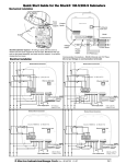
R9120
rev A
ModHopper quick start guide.
Step 1: Modbus Address.
Step 2: System Switches.
Every Modbus device in the system
must have a unique address. This
includes each Modhopper and every
attached RS485/Modbus device.
For most systems, set all of
the system switches to the
"off" position.
The only switch that is
required is the RS485 baud
rate option. Set this to "off"
for 19200 or to the "on"
position for 9600. The
example to the right is a
default configuration for 9600
baud on the RS485
connection.
Select an address, and set the
dipswitches to match.
The sum of the value of the switches is
the address. In the example to the right,
address 52 is set by placing switch 4,
16 and 32 to the on position.
Note: 4 + 16 + 32 = 52
Step 3: Pulse Hookup.
Attach any "dry contact" pulse output meters to the pulse input terminals as shown in
the wiring diagram. The ModHopper can support 2 pulse devices.
The ModHopper can be attached to many types of pulse output meter. Power, water,
gas, etc. For “KYZ” type power meters, use the normally open contacts, usually
labeled “K and Z”
Step 4: RS485 Modbus Hookup.
Attach any Modbus slave or master devices to the 485 terminals as shown in the
wiring diagram. Up to 32 Modbus devices may be attached to each ModHopper.
Note: when attaching Modbus devices, it is not necessary to specify if the device is a
master (AcquiSuite, PLC, etc) or a slave device (power meter, sensor, etc). The
ModHopper will automatically detect the master and handle it appropriately.
Step 5: Attach the Antenna.
Attach the Antenna to the side of the ModHopper. The antenna should be finger tight
and be placed in a vertical position.
Step 6: Power up the ModHopper.
Attach the power brick to the power jack on the ModHopper. The device should power up and be ready in
a few seconds. The LEDs should blink in the following manner.
●
●
●
●
●
The "Alive" LED should start to blink about once per second.
The Alarm LED will blink when transmission errors occur.
The RF TX/RX LEDs will blink when the radio is receiving or transmitting data.
The RS485 LEDs will blink for local Modbus activity.
The Pulse input LEDs will light when the corresponding pulse input terminals are closed.
When the ModHopper is operating, the Test Button can be used to report the signal strength received by
the ModHopper from another unit. Press and hold down the test button. The status LEDs will light up as
a bar graph display. Each LED is approximately 10% of scale. For example if PULSE 1 and 2 are on, the received
strength is approximately 20% to 29%. For useful signal reporting, it is important to turn off all but one other ModHopper.
For complete instructions and Modbus register listings, please consult the ModHopper user manual.
3300 NW 211th Terrace,
Hillsboro, OR
97124 Ph: +1-503-601-2099
Draft: Revised: Jun 21, 2010