1
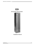
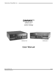
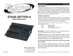
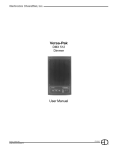
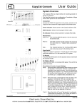
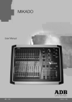
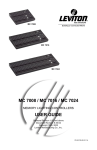
Plus Plus Control Console User Manual Revision 7, May 1998 © 1997, 1998, Electronics Diversified, Inc. 070-0580 1 Plus INTRODUCTION ABOUT THE PLUS CONSOLE The Plus Console is designed to support a series of very basic control concepts established in the lighting industry. These concepts are based on the fundamental idea of standard two-scene preset operation with a healthy twist. The layout of the Plus controls suggests a two-scene preset background with two familiar rows of Channel sliders and a basic set of Crossfaders. Each Channel and Submaster is equipped with a Bump Button. Bump controls allow the operator to select the feature and the level of the bump. Plus also allows the operator to double the channel capacity with the scene mode switch. When in 1 scene mode, the lower row of sliders simply add to the upper row of sliders. This feature makes it quick and easy to gain additional channel control when needed. Plus incorporates the page concept for memory storage in both Submaster and Preset memories. Each is equipped with a page switch. This method layers the storage and allows the operator to select a recorded memory from any page at any time. Pages can be switched without affecting the current output. Plus offers an Independent Fader with a pile-on or inhibit capacity. This Fader can accept both preset memories and Submaster memories in a manual or timed mode. When a memory is loaded in either Fader 1 or 2, the Independent Fader, selected to Inhibit, and the channel slider can subtract any channels from the recorded memory output. This unique feature allows fast edits and adjustments based on live circumstances. Plus also supports a monochromatic CRT, Off Line Printer, a Hand Held Remote for dimmer address, Off Line Storage for up to 40 shows, Alphanumeric show labels, Preview capacities, and a simple Effects package. All of these features are standard in an economical control package. So, as you step through this Guide, the real advantages will become clear. For best results, work with the Guide and the Plus together to highlight the features of the console. We think the Plus is a step above the average preset control console. This Operational Guide is supplied with your system. Copies of this guide may be obtained from Electronics Diversified, Inc. for a nominal charge. It is recommended that you copy those portions of this manual applicable to your present use in the installation, maintenance or repair and preserve the original in a safe place. © 1998, by Electronics Diversified, Inc. All rights reserved. No part of this manual may be reproduced by any means, graphic, electronic, or mechanical, including photocopying, recording, taping, or information storage and retrieval systems, without the express written permission of Electronics Diversified, Inc., except in connection with installation, repair and maintenance of Electronics Diversified, Inc. systems. 2 Plus TABLE OF CONTENTS 1-Scene Preset . . . . . . . . . . . . . . . . . . . . . . . . . . . . 20 4-Scene Preset . . . . . . . . . . . . . . . . . . . . . . . . . . . . 22 OVERVIEW Front Panel . . . . . . . . . . . . . . . . . . . . . . . . . . . . . . . . . . . 4 Rear Panel . . . . . . . . . . . . . . . . . . . . . . . . . . . . . . . . . . . 4 Side Panel . . . . . . . . . . . . . . . . . . . . . . . . . . . . . . . . . . . .5 INDEPENDENT FADER Pile-On Mode . . . . . . . . . . . . . . . . . . . . . . . . . . . . . . . . 24 Inhibit Mode . . . . . . . . . . . . . . . . . . . . . . . . . . . . . . . . . . 24 SET-UP CRT Display. . . . . . . . . . . . . . . . . . . . . . . . . . . . . . . . . . .6 Keypad Display. . . . . . . . . . . . . . . . . . . . . . . . . . . . . . . . 6 RECORDING A PRESET Set Fade Time . . . . . . . . . . . . . . . . . . . . . . . . . . . . . . . 25 RECORDING A SUBMASTER To Record . . . . . . . . . . . . . . . . . . . . . . . . . . . . . . . . . . . 26 CONTROLS Keypad . . . . . . . . . . . . . . . . . . . . . . . . . . . . . . . . . . . . . . .8 Shifted Keys . . . . . . . . . . . . . . . . . . . . . . . . . . . . . . . . . . 9 Switches . . . . . . . . . . . . . . . . . . . . . . . . . . . . . . . . . . . . 10 Sliders . . . . . . . . . . . . . . . . . . . . . . . . . . . . . . . . . . . . . 11 Displays . . . . . . . . . . . . . . . . . . . . . . . . . . . . . . . . . . . . . 12 Effects . . . . . . . . . . . . . . . . . . . . . . . . . . . . . . . . . . . . . . 13 FADER OPERATIONS Loading a Preset . . . . . . . . . . . . . . . . . . . . . . . . . . . . . . 27 Loading a Submaster . . . . . . . . . . . . . . . . . . . . . . . . . . 27 Submaster Operation . . . . . . . . . . . . . . . . . . . . . . . . . . 28 EDITING Edit a Preset . . . . . . . . . . . . . . . . . . . . . . . . . . . . . . . . . 29 Edit a Submaster . . . . . . . . . . . . . . . . . . . . . . . . . . . . . 31 EFFECTS OPERATION Preparation . . . . . . . . . . . . . . . . . . . . . . . . . . . . . . . . . . . .34 PATCH OPERATION Access Patch . . . . . . . . . . . . . . . . . . . . . . . . . . . . . . . . . 14 Assign Patch . . . . . . . . . . . . . . . . . . . . . . . . . . . . . . . . . 14 THRU Function. . . . . . . . . . . . . . . . . . . . . . . . . . . . . . . . 14 AND Function. . . . . . . . . . . . . . . . . . . . . . . . . . . . . . . . . 15 Park Feature. . . . . . . . . . . . . . . . . . . . . . . . . . . . . . . . . 15 REMOTE RECORD Plus to SubCommander. . . . . . . . . . . . . . . . . . . . . . . . . 35 OFF-LINE STORAGE Save Show . . . . . . . . . . . . . . . . . . . . . . . . . . . . . . . . . . 36 Load show . . . . . . . . . . . . . . . . . . . . . . . . . . . . . . . . . . . 36 PRINTERS Set-Up . . . . . . . . . . . . . . . . . . . . . . . . . . . . . . . . . . . . . . 37 BUMP SET-UP Configure . . . . . . . . . . . . . . . . . . . . . . . . . . . . . . . . . . . . 16 Playback. . . . . . . . . . . . . . . . . . . . . . . . . . . . . . . . . . . . . 16 CRT DISPLAYS Set-Up Screen . . . . . . . . . . . . . . . . . . . . . . . . . . . . . . . . 38 Stage Screen . . . . . . . . . . . . . . . . . . . . . . . . . . . . . . . . 38 Patch Screen . . . . . . . . . . . . . . . . . . . . . . . . . . . . . . . . . 39 Preset Screen . . . . . . . . . . . . . . . . . . . . . . . . . . . . . . . . . 39 Submaster Screen . . . . . . . . . . . . . . . . . . . . . . . . . . . . 40 Save Screen . . . . . . . . . . . . . . . . . . . . . . . . . . . . . . . . . 40 Disk Screen . . . . . . . . . . . . . . . . . . . . . . . . . . . . . . . . . . 41 Help Screen . . . . . . . . . . . . . . . . . . . . . . . . . . . . . . . . . . 41 PRESET OPERATION Preparation . . . . . . . . . . . . . . . . . . . . . . . . . . . . . . . . . . 17 2-Scene Preset . . . . . . . . . . . . . . . . . . . . . . . . . . . . 18 3 ADDENDUM Plus OVERVIEW FRONT PANEL 01. COMMAND KEYPAD: 2 5 3 7 9 Numeric Keypad and LED display with keys for access to Patch, Channel, Level, Preset, Submaster and Disk functions. 10 02. KEY SWITCHES: Key access to both power and record functions. 03. EFFECTS CONTROLS: Program controls for Chase effects to include dedicated level and rate controls. 04. SUBMASTERS: Four pages of 12 overlapping submaster memories with bump buttons and bank load capacities. 05. PLAYBACK CONTROLS: Plus 1 4 6 Split dipless cross-faders with timer controls and LED preset displays. An Independent fader for pile-on or inhibitive capacity. Bump mode controls with off, level control, and solo selections. Grand Master and blackout switch. 8 06. LOAD/RECORD KEYS: When selected with preset key loads to a specified fader. When selected with preset key records to a specified preset. 07. INDICATOR PACKAGE: For Power, Back-Up and Overtemp conditions. 08. BUMP BUTTONS: Channel bump buttons and/or preset record keys. 09. CHANNEL CONTROLS: Single or two-scene channel controllers for individual level setting. 10. DISK DRIVE: Multi-Show off-line storage of recorded information. REAR PANEL 1 2 3 5 6 8 9 10 1 11 01. SCRIPT LIGHT RECEPTACLE: For optional Console Script Lights. 02. DMX-AMX OUT: Console output locking 5-pin XLR connector. 03. HOUSELIGHTS: 12 4 4 7 12 D15-pin connector for analog houselights. 04. ANALOG OUTPUT PORTS: 2 D25-pin connectors for 0-10 VDC output. (1-48 channel capacity) 05. ANALOG BACK-UP: For connection to EDI Multi-Link 10-channel backup. Function switch must be selected. 06. PRINTER PORT: D25-pin for connection to standard parallel printer. (IBM-PC Parallel) 07. OUTPUT SELECTOR SWITCH: Selects console output options: DMX-512; AMX-192; or Analog back-up. 4 Plus OVERVIEW 08. VIDEO OUTPUT: D9-pin connector for standard monochromatic video output. (TTL-Monochrome) 09. MONITOR POWER: Grounded Edison connector for monitor: 100 Watts max. 10. CONSOLE POWER: Grounded recessed Edison connector for console power, 3 Amps max. 11. FUSE HOLDER: 3 Amp fuse holder. (Not user replaceable) 12. SCRIPT LIGHT DIMMER: 12-Volt, 200-300 mA, 2.4 Watt low-intensity lamp. SIDE PANEL Disk Drive DISK HANDLING PROCEDURE: DISK DRIVE: 3.5" IBM format, 1.44MB. Disks must be formatted by the Plus console before use. Insert the diskette as illustrated. Do not force it into the drive. If the diskette will not insert easily, it is not correctly oriented. To eject the diskette, push the small button on the disk drive. To protect your data: Indicator Light Do not expose to high temperatures. Eject Button Do not store near magnetic fields. 3.5" Disk Do not eject a diskette while the disk drive indicator light is on. This could result in loss of data or incomplete loading of a show. Wait until the indicator light goes off before ejecting. Write-protect Tab TO FORMAT A DISK: Disk must be formatted before recording show information to the disk. Press and hold Shift and Press 5 Select 12; press Enter When format is complete, disk will stop and console restores. WRITE PROTECTION: Write protection locks the disk, preventing alteration of stored data. To write protect the disk: Orient the diskette so that the round metal circle is pointed toward you. With the metal flap on top, the write-protect tab is located in the lower right-hand corner. If this tab is closed, the diskette is not Write Protected. If the tab is open, the diskette is Write Protected, and no new data can be recorded. Diskettes may be purchased from EDl (Part#119-0058) or any computer supply house. Diskettes should be double-sided, high-density, MF2-HD diskette equivalent. Two non-formatted disks are supplied with the Plus console. 5 Plus SET-UP CRT DISPLAY TO ACCESS SET-UP: Hold (SHIFT) and press (5) (SETUP). [ SETUP ] 1. 3. 5. 7. 9. 11. 13. Test Channels Test Dimmers Show Version Unity Patch Auto Follow Wrapping Check Disk Midi Address SE 2. Change Channel Count 4. Change Dimmer Count 6. Clear Memory 8. Modulus Patch 10. +Independent Not Assigned GM 12. Format Disk 14. Remote Store UP NOTE: Use NEXT, LAST keys to position highlight bar on CRT or enter number and press ENTER. On models without CRT, enter number on keypad. For item to be selected, press ENTER to start. 01 KEYPAD DISPLAY 1. TEST CHANNELS: Select: All Channels are set to the level of Fader 1 and individually set to the level of Fader 2 at a rate determined by the Independent Fader. Press CLEAR to stop test. 2. CHANGE CHANNEL COUNT: Select: Current channel count is displayed. Select new channel count less than available channels and press ENTER. 3. TEST DIMMERS: Select: All Dimmers are set to the level of Fader 1, and individually set to the level of Fader 2 at a rate determined by the Independent Fader. Press CLEAR to stop test. 04. CHANGE DIMMER COUNT: Select: Current Dimmer count is displayed. Select new dimmer count less than 512 and press ENTER. Patch operations are limited to number selected. 05. SHOW VERSION: Select: Current software version installed is displayed. 6 Plus SET-UP 06. CLEAR MEMORY: Select: [ SETUP ] Clears recorded Presets, Submasters and Faders. Patch defaults to Unity Patch. 1. 3. 5. 7. 9. 11. 13. Test Channels Test Dimmers Show Version Unity Patch Auto Follow Wrapping Check Disk Midi Address 2. Change Channel Count 4. Change Dimmer Count 6. Clear Memory 8. Modulus Patch 10. +Independent Not Assigned GM 12. Format Disk 14. Remote Store 07. UNITY PATCH: Select: Installs one Dimmer per Channel patch for available channels. 08. MODULUS PATCH: Select: Installs wrap-around patch for Dimmers to Channels. 09. AUTO-FOLLOW WRAP: Select: SE UP Allows all four preset pages to Auto-follow into Crossfades by loading the first preset of the next page after the last preset of the current page is displayed. 01 Auto-follow stops at the last recorded preset on page 4. 10. INDEPENDENT FADER ASSIGN: Select: Assigns or releases Independent Fader to Grand Master control. 11. CHECK DISK: Select: Checks and confirms information stored on disk. 12. FORMAT DISK: Select: (Required for new disk.) NOTE: Formatting erases all information on disk. 13. MIDI ADDRESS: Select: Optional Midi protocol. 14. REMOTE STORE: Select: Assigns output to Page and Playback number on the Subcommander. The user will be prompted for the SubCommander page and playback, page in Channel window, and playback in Level window. Press CLEAR to stop any test. Press CLEAR to quit Set-Up function. 7 Plus CONTROLS KEYPAD Upon pressing ENTER, a window blinks, indicating where the next data entry will go. CLEAR removes data entry in the current window and moves to the next window, left. ENTER accepts the data in the current window and moves to the next window, right. AT defers acceptance of data in the current window and moves to the next window, right. HINT: The keypad is the entrance to Blind/Edit functions. This capacity allows access to memory functions different from the Stage output. In the Blind Mode, edits to levels may occur without affecting the existing stage picture. = AT: Ends entry and moves active window to the right. EXAMPLE: = AND: Sets of Dimmers or Channels are selected. EXAMPLE: =THRU: Groups of Dimmers or Channels are selected. EXAMPLE: = CLEAR: Removes last entry. EXAMPLE: = NEXT: Selects the next number. EXAMPLE: = LAST: Selects the previous number. EXAMPLE: = ENTER: Accepts numbers and stores information. EXAMPLE: = FL: Assigns 100% value to entry. EXAMPLE: = PRESET: Selects editing of recorded Presets. EXAMPLE: 8 Plus CONTROLS SHIFTED KEYS Some keys have names on the front of the key. To access this function, Press and Hold the SHIFT key and select the desired function key. = NON-DIM: Sets a Dimmer to a Non-Dim when in the Patch mode. = RATE: Selects fade rate assignment for Preset and Submasters when in the Submaster or Preset screen. = SUB: Selects editing of a recorded Submaster. = SET-UP: Accesses system Setup options. = SAVE: Records system memory to the disk. = PRINT: Prints selected information. = LOAD: Loads disk information into system memory. = HELP: Accesses system Help program. = STAGE: Accesses screen for direct channel output or current output status. = PATCH: For assignment of dimmers to control channels at levels. 9 Plus CONTROLS SWITCHES 1. CHANNEL MODE: 2. STAGE/BLIND: Selects single or two-scene operation. 1 Selects all outputs for Stage Record or only channel outputs for Blind. 2 3. SUBMASTER PAGE: 4. BUMP MODE: Selects active Submaster memory, pages 1 through 4. 3 Selects Bump button function: SOLO, 4 5 ON, or 6 OFF. 5. AUTO FOLLOW: Enables loading next sequential preset onto next fader automatically. 6. PRESET PAGE: Up to 4 Preset pages are available with the number of channel bump buttons, equalling the number of memory spaces available. 7. BLACKOUT: In the Black position, all levels are forced to OFF immediately. 8. INDEPENDENT MODE: Selects Pile-on or Inhibit mode for the Independent Fader. 9. RECORD: Selects recording of active levels into Presets, Submasters or Faders. 7 8 9 10 10. LOAD: Selects Fader to be loaded. 10 Plus CONTROLS SLIDERS 1. BUMP MASTER: 2. INDEPENDENT FADE RATE TIMER: Controls minimum output level for Bump functions. Sets fade times for Independent Fader. 7 3. SUBMASTERS: Twelve individual Pile-on memory faders. 8 1 4. GRAND MASTER: Controls overall console output level. 5. 2 INDEPENDENT FADER: Third Playback Fader for Submaster and Preset memories, or: Manual control of Channels. 6. CROSSFADERS: 7. CROSSFADER TIMERS: Produces split/dipless fades between two scenes. 9 Sets fade time for associated Faders; or: Auto setting for recorded time playback. 8. SCENE 1 SLIDERS: Sets levels for Scene 1, used by Fader 1 in manual mode; or: Used as source for levels in BLIND mode. 9. 3 4 5 SCENE 2 SLIDERS: Sets levels for Scene 2, used by Fader 2 in manual mode; or: Used as source for additional levels in 1 Scene mode; also a source for Blind in 1-Scene mode. 6 11 Plus CONTROLS DISPLAYS 1 P24 2 01 1. 3 DIMMER/PRESET WINDOW: Displays the current dimmer, Preset or Submaster for Patch and Edit functions. 2. -- CHANNEL WINDOW: Displays the selected Channel for Patch and Edit functions. 3. LEVEL WINDOW: Displays the selected Level for Patch and Edit functions. (Blinking numbers means next entry in this window. To advance active window, press ENTER or AT. 4 To access previous window, press CLEAR). 4. FADER WINDOWS: Display the Fader source. 5 Modes --Hold Status: H1 H2 1-Scene Manual: 5 Preset: Submaster: 5. -2 -1 2-Scene Manual: -- -14 28 01 ● ● BARGRAPHS: Indicate active status of Crossfades. 6. 6 7 8 OVERTEMP: Indicates a dimmer cabinet overtemp condition. 7. BACKUP: Indicates when the console is in Backup mode. 8. POWER: Indicates console ON. 12 12 Plus CONTROLS EFFECTS 7 8 01. ON/OFF: Turns Effects On and Off. 02. STEPS: 4 Determines the number of 'looks' in the Effect. 03. DIRECTION: Determines the direction of the Effect. 04. STEP: 2 Indicates a 'look' currently active by the Effect generator. 05. RUN/STOP: 3 Runs or stops the Effect in progress. 06. STEP/HOLD: Holds a running Effect, or steps a stopped Effect. 5 07. BLACKOUT: 1 Forces Effect levels to zero output. 10 08. RATE SLIDER: Varies the speed of the Effect. 09. MASTER: Varies the intensity of the Effect. 9 10. PAGE: 6 Selects Submaster memory page in which the Effect is active. 13 Plus PATCH OPERATION TO ACCESS PATCH: Press and hold (SHIFT), press (ENTER). [ PATCH ] DIM CH % Displays Patch screen on CRT. 1 2 3 4 5 6 7 8 9 10 11 12 13 14 15 1 2 3 4 5 6 7 8 9 10 11 12 13 14 15 FL FL FL FL FL FL FL FL FL FL FL FL FL FL FL TO ASSIGN UNITY: 16 17 18 19 20 21 22 23 24 25 26 27 28 29 30 16 17 18 19 20 21 22 23 24 25 26 27 28 29 30 FL FL FL FL FL FL FL FL FL FL FL FL FL FL FL Shows SETUP Screen. 31 32 33 34 35 36 37 38 39 40 41 42 43 44 45 31 32 33 34 35 36 37 38 39 40 41 42 43 44 45 FL FL FL FL FL FL FL FL FL FL FL FL FL FL FL Installs one dimmer per channel patch for available channels. 46 47 48 49 50 51 52 53 54 55 56 57 58 59 60 46 47 48 49 50 51 52 53 54 55 56 57 58 59 60 FL FL FL FL FL FL FL FL FL FL FL FL FL FL FL TO ASSIGN MODULUS: 61 62 63 64 65 66 67 68 69 70 71 72 73 74 75 61 62 63 64 65 66 67 68 69 70 71 72 73 74 75 FL FL FL FL FL FL FL FL FL FL FL FL FL FL FL Shows SETUP Screen. Installs wrap-around patch for dimmers to channels. (Used for Test purposes only.) TO ASSIGN PATCH: --- When Dimmer/Preset window is blank, select Dimmer or Dimmers to be assigned. - -2 Press (AT) and select the proportion of the channel level to be output. Press (AT) and select the channel to control the Dimmer(s). 5 FL Press (ENTER). 3 (ENTER) advances the next number in the Dimmer/Preset window. Repeat until all system Dimmers are assigned to the available channels. Record Patch to disk (position #) for safety. THRU FUNCTION: 2 The THRU key allows a continuous section of Dimmers to be selected as a group for patch operations. --5 10 FL 14 Plus PATCH OPERATION AND FUNCTION: The AND key allows Dimmers and groups of Dimmers to be handled as a combined set for patch operations. [ PATCH ] DIM CH % 1 2 3 4 5 6 7 8 9 10 11 12 13 14 15 1 2 3 4 5 6 15 15 15 15 15 12 13 14 15 FL FL FL FL FL FL 75 75 75 75 75 FL FL FL FL 16 17 18 19 20 21 22 23 24 25 26 27 28 29 30 16 17 18 19 20 15 15 15 15 15 15 15 15 15 15 FL FL FL FL FL 75 75 75 75 75 75 75 75 75 75 (ENTER) advances the next number in the Dimmer/Preset window. 31 32 33 34 35 36 37 38 39 40 41 42 43 44 45 31 32 33 34 35 36 37 38 39 15 41 42 43 44 45 FL FL FL FL FL FL FL FL FL 75 FL FL FL FL FL 46 47 48 49 50 51 52 53 54 55 56 57 58 59 60 46 47 48 49 50 51 52 53 54 55 56 57 58 59 60 FL FL FL FL FL FL FL FL FL FL FL FL FL FL FL 61 62 63 64 65 66 67 68 69 70 71 72 73 74 75 61 62 63 64 65 66 67 68 69 70 71 72 73 74 75 FL FL FL FL FL FL FL FL FL FL FL FL FL FL FL 40 15 75 (Preset/Dimmer window will look like this after last entry). PARK FEATURE: [ PATCH ] DIM CH % Hold (SHIFT) and press (ENTER). 1 2 3 4 5 6 7 8 9 10 11 12 13 14 15 1 2 3 4 5 6 7 8 9 10 11 12 13 14 15 FL FL FL FL FL FL FL FL FL FL FL FL FL FL FL 16 17 18 19 20 21 22 23 24 25 26 27 28 29 30 16 17 18 19 20 21 22 23 24 25 26 27 28 29 30 FL FL FL FL FL FL FL FL FL FL FL FL FL FL FL Patch Screen is displayed. Park feature assigns constant Dimmer output regardless of fader positions. 31 32 33 34 35 36 37 38 39 40 41 42 43 44 45 31 32 33 34 35 36 37 38 39 40 41 42 43 44 45 FL FL FL FL FL FL FL FL FL FL FL FL FL FL FL Select Dimmer or Dimmers, press (AT) to change to Channel window and press (FL) to select PARK. 46 47 48 49 50 51 52 53 54 55 56 57 58 59 60 46 47 48 49 50 51 52 53 54 55 56 57 58 59 60 FL FL FL FL FL FL FL FL FL FL FL FL FL FL FL 61 62 63 64 65 66 67 68 69 70 71 72 73 74 75 61 62 63 64 65 66 67 68 69 70 71 72 73 74 75 FL FL FL FL FL FL FL FL FL FL FL FL FL FL FL p fl p fl Press (AT) to change to Level window and select output level desired and press (ENTER). Dimmers will output at the assigned level until reassigned. 50 15 Plus BUMP SET-UP CONFIGURE BUMP MASTER: The Bump Master slider determines the output level for bumped Channels. BUMP MODE: SOLO: Outputs levels as in normal bump mode, except all channels not involved with the bump are held at zero for the duration of the bump. ON: Normal Bumps are enabled. Pressing a Bump button adds an individual Channel or a Submaster Channel into the console output, based on the level of the Bump Master. OFF: Bump buttons are deactivated on the console. PLAYBACK CHANNEL BUMPS: Channel Bumps set the output level of an individual Channel into the console output, based on the level of the Bump Master. If the channel level is at 25% and the Bump Master is at FULL, the bumped level is at 25% SUBMASTER BUMPS: Submaster Bumps set the output level of all the channels stored in the Submaster to the level of the Bump Master. If the channel level is at 25% and the Bump Master is at FULL, the bumped level is at 25% 16 Plus PRESET OPERATION PREPARATION If you plan to follow the examples set on the following pages, make sure the front panel controls are set in the following positions: 01. Memory access switch keyed 'On' 02. Grand Master at 100% 1 03. Blackout Switch at Normal 04. Time Faders at '0' 8 11 9 7 05. Ind Fader at '0' 4 06. Ind Switch at 'Pile-On' 07. Preset Page at '1' 08. Submaster Page at '1' 09. Auto Follow 'On' 10. Fader 1 & 2 split and set at '0' 11. Bump Switch set 'Off' 3 -1 6 12. Effect Switch set 'Off' If you plan to address the dimmer bank, make sure the data cable is plugged into the back of the console and the output switch is set to the proper protocol. When the front panel controls match the above outline, proceed to the next step. 2 5 10 12 17 Plus 2-SCENE PRESET OPERATION SETTING LEVELS TWO-SCENE MODE: Set Channel Mode switch to "2-SCENE". Scene 1 defaults to Fader 1, Scene 2 defaults to Fader 2. SET SCENE 1 LEVELS: Set sliders to desired levels. SET SCENE 2 LEVELS: Set sliders to desired levels. SET FADE TIME: Set Fader Time sliders to desired fader playback time. 18 Plus 2-SCENE PRESET OPERATION PLAYBACK PLAY SCENE: Move Crossfader 1 to position 10. Bargraph will follow based on set Fader time. -1 -2 CROSSFADE: -1 -2 Move both Faders together in the same direction. One moves to '0', the other moves to '10'. Bargraphs follow according to set fade time. INDEPENDENT: Assigned to Scene 1 channels in two-scene mode or: Assigned to ALL channels in one-scene mode. 19 Plus 1-SCENE PRESET OPERATION SETTING LEVELS ONE-SCENE MODE: Set Channel Mode switch to "1-SCENE". The second row of scene sliders is a continuation of Scene 1, doubling the console channel capacity. INDEPENDENT FADER is assigned top and bottom row of channels in one-scene mode. SET SCENE 1 LEVELS: Set sliders to desired levels for Scene1. SET FADE TIME: Set Fader Time sliders to desired fader playback time 1 2 HOLDING FEATURE: H- Press and hold (RECORD); Press (LOAD) under Fader 1. Fader window displays 'H -'. Fade time is captured. (With "Holding" active, channels and levels are stored for playback and are no longer affected by slider positions.) SET SCENE LEVELS: Set Scene 1 sliders and Scene 2 sliders to levels desired for Scene 2. SET FADE TIME: Set Fader 2 Time Slider to desired fader playback time. 20 Plus 1-SCENE PRESET OPERATION HOLDING FEATURE: H- Press and hold (RECORD); Press (LOAD) under Fader 2. Fader window displays 'H -'. Fade time is captured. (With "Holding" active, channels and levels are stored for playback and are no longer affected by slider positions.) TO RESTORE MANUAL CONTROL: At any time you may press (LOAD) under the holding Fader to return to manual scene control. NOTE: If you restore manual control to the Fader, you will lose the Holding Scene. PLAYBACK PLAY SCENE: -1 -2 Move Crossfader 1 to position 10. Bargraph will follow based on set Fader time. CROSSFADE: -1 -2 Move both Faders together in the same direction. One moves to '0', the other moves to '10'. Bargraphs follow according to set fade time. INDEPENDENT FADER: Always assigned to SCENE 1 channels in two-scene mode or: Always assigned to ALL channels in one-scene mode. 21 Plus 4-SCENE PRESET OPERATION SETTING LEVELS ZERO CROSSFADERS: Set Fader 1 and Fader 2 to ZERO position. TWO-SCENE MODE: Set Channel Mode switch to "2-SCENE". Scene 1 defaults to Fader 1, Scene 2 defaults to Fader 2. SET SCENE 1 LEVELS: Set sliders to desired levels for Scene 1. SET FADE TIME: (See Page 20.) HOLDING FEATURE: H1 Press and hold (RECORD); Press (LOAD) under Fader 1. Fader window displays 'H 1'. Fade time is captured. (With "Holding" active, channels and levels are stored for playback and are no longer affected by slider positions.) (See Page 20 for illustration). SET SCENE 2 LEVELS: Set sliders to desired levels for Scene 2. SET FADE TIME: (See Page 20). HOLDING FEATURE: H2 Press and hold (RECORD); Press (LOAD) under Fader 2. Fader window displays 'H 2'. Fade time is captured. (With "Holding" active, channels and levels are stored for playback and are no longer affected by slider positions.) (See Page 21 for illustration). SET SCENE 3 LEVELS: Set Scene 1 sliders to desired levels for Scene 3. 22 Plus 4-SCENE PRESET OPERATION SET SCENE 4 LEVELS: Set Scene 2 sliders to desired levels for Scene 4. PLAYBACK PLAYBACK SCENE 1: -1 H2 H1 H2 In playback Time, sliders must be in Auto/Hold position for the first two scenes. Move Crossfader 1 to position 10. Scene 1 fades in over stored fade time. CROSSFADE TO SCENE 2: Simultaneously move Fader 1 to 0 and Fader 2 to 10. Scene 1 fades out at its stored fade rate and Scene 2 fades in at its stored fade rate. 1 When Scene 1 reaches 0 the Fader 1 display will show '-1'. 2 -1 -2 -1 CROSSFADE TO SCENE 3: -2 After completing Scenes 1 & 2, set Time sliders to the desired fade time. Simultaneously move Fader 1 to 10 and Fader 2 to 0. Scene 2 fades out at its stored fade rate and Scene 3 fades in at its set fade rate. When Scene 2 reaches 0 the Fader 2 display will show '-2'. CROSSFADE TO SCENE 4: Simultaneously move Fader 1 to 0 and Fader 2 to 10. 3 Scene 3 fades out at its set fade rate and Scene 4 fades in at its set fade rate. 4 23 Plus INDEPENDENT FADER PILE-ON MODE In Pile-On mode, channel levels assigned to the Independent Fader add to the output of other sections of the console. In this mode the Independent Fader relates to the Grand Master in two ways; fully independent and scaled. When the Independent Fader is assigned to the Grand Master, the Pile-On output of the Independent Fader is scaled by the level of the Grand Master. If the Independent Fader is fully independent, the output is not affected by the Grand Master, so if the Grand Master is at zero, the levels generated by the Independent Fader will be displayed. Displays Setup screen. Reviews configuration. To temporarily add levels or new channels to a recorded preset, position IND MODE switch to Pile-On. Set levels greater than recorded. Move IND FADER handle up and selected channels will 'Pile On'. INHIBIT MODE To temporarily remove channels stored in a preset, move the IND MODE switch to Inhibit position. In Inhibit mode, channels assigned to the Independent Fader are reduced in intensity according to the level assignments of the individual channels. Position selected channel sliders to Full output. Move IND FADER handle up and selected channels will move to '0'. In this mode, if a channel assigned to the Independent Fader with a level of 50% and the Fader is at Full, the selected channels' level is reduced to 50% of its computed output level. Press (LOAD) to set Manual mode. Set IND MODE switch to INHIBIT. Set channel sliders to percentage to be removed. Move IND Fader to Full (10). Selected channels will be reduced according to the proportion set on the Channel slider. Move the IND Fader to 0. Channels are restored. When action is complete, restore mode switch to 'Pile-On' position. 24 Plus RECORDING A PRESET TO RECORD A PRESET: Set levels on sliders in either One- or Two-Scene mode. Select Preset page number. Press and hold (RECORD), then press the Channel Bump button corresponding to the preset number to be stored. Preset window will blink to confirm. HINT: Use sequential numbers to store sequential 'looks'. SET FADE TIME: s 0 15 Press Preset Button followed by a Preset Number to access Fade Times 0 Hold (SHIFT) and press (AND). (RATE key) Select fade time minutes (0 - 9). Press (AT) and select fade time seconds (0 - 99). Press (ENTER) to complete. s 2 30 FADE TIME: 0 If a Fader Time slider is set for a manual time, the stored Preset or Submaster fade time is not used. Set Fade Time sliders to AUTO for use of stored fade rate. 25 Plus RECORDING A SUBMASTER TO RECORD A SUBMASTER: Set levels on sliders in either One- or Two-Scene mode Select Submaster page number. • Press and hold (RECORD), then press the Bump button under the Submaster number to be stored. • Preset window will blink to confirm. HINT: Use sequential numbers to store sequential 'looks'. 26 Plus FADER OPERATIONS LOADING A PRESET LOADING A FADER: Once Preset level information has been recorded and stored, the recorded infomation can be played back on any Fader. TO LOAD FADER WITH A PRESET: Press and hold (LOAD) button for Fader and press Bump button under Channel number for the Preset. LOAD FADER: Preset number will appear in Preset window. SELECT AUTO FOLLOW: Select Auto Follow Switch if you wish the next sequential number to appear in the empty Fader window. -1 SET FADE TIME: 11 Move Time slider over Crossfader to desired playback fade rate. PLAY FADER: Move Fader handle towards 10. Bargraph will follow manually or according to the fade rate selected. CLEAR A FADER OR RESTORE MANUAL CONTROL: Press the (LOAD) button under the Crosssfader. NOTE: Pressing the LOAD button will release the information assigned to the Fader. LOADING A SUBMASTER • LOADING A FADER: • Once Submaster level information has been recorded and stored, the recorded infomation can be played back on any Fader. TO LOAD FADER WITH A SUBMASTER: Press and hold (LOAD) button for Fader and press Bump button under Channel number for the Submaster. LOAD FADER: Submaster number will appear in Preset window. SELECT AUTO FOLLOW: Select Auto Follow Switch if you wish the next sequential number to appear in the empty Fader window. (NOTE: Console will not AUTO-FOLLOW with a Submaster loaded on a Crossfader.) 27 Plus FADER OPERATIONS • SET FADE TIME: 11 • Move Time slider over Crossfader to desired playback fade rate. PLAY FADER: Move Fader handle towards 10. Bargraph will follow manually or according to the fade rate selected. CLEAR A FADER OR RESTORE MANUAL CONTROL: Press the (LOAD) button under the Crosssfader. (NOTE: Pressing the LOAD button will release the information assigned to the Fader.) SUBMASTER OPERATION: Submasters may be manually controlled or loaded on a fader for time or crossfade control. To operate a submaster manually: Select active Submaster page; Move Submaster Slider to desired level; Submaster outputs are controlled by the Grand Master. The Submaster page can be changed when sliders are active or passive. This allows active Submasters from different pages to be played at the same time. When a Submaster from a previous page is returned to a '0' position, the page automatically advances to the current page. The active page number is displayed at the top of the Submaster display area in the Stage screen on the CRT. [ STAGE ] The previous page number is always displayed under the Slider on the CRT. Submasters may be edited blind on the CRT by pressing Shift Preset and selecting the number and page of the Submaster to be edited. FADER SUBMASTER Preset Time Percent Page: 1 -1- Pg1-Pr12 00:00.0 FL 1 2 3 4 5 6 7 8 9 10 11 12 Bounce -2- Pg2-Sm10 00:00.0 FL 50 50 25 Page :1 +INDManual 00:00.0 25 Active Page 4 4 EFFECTS Running 75 75 Steps : 4 Master : 0 28 Plus EDITING EDIT A PRESET MEMORY ACCESS: To record or edit Memories, set Key Switch to ON. KEYPAD: 1. Upon pressing (ENTER), a window blinks, indicating where the next data entry will go. 4 2. (CLEAR) removes data entry in the current window and moves to the next window, left. 3. (ENTER) accepts the data in the current window and moves to the next window, right. 4. (AT) defers acceptance of data in the current window and moves to the next window, right. 2 1, 3 PRESET PAGE SWITCH: Page switches select the memory page in which memory operations occur. The pages memory capacity corresponds to the number of bump buttons for that section. VIEW PRESET (for CRT Only): [ PRESET ] Page : 01 Number : 01 Fade Rate : 00:00.0 Press (PRESET), select Number, Press (ENTER). Used by: None # CH 01 02 03 04 05 06 07 08 09 10 11 12 13 14 15 16 17 18 19 20 21 22 23 24 % FL FL FL 00 00 00 00 00 00 00 00 00 00 00 00 00 00 00 00 00 00 00 00 00 Displays the next sequential Preset. 25 26 27 28 29 30 31 32 33 34 35 36 37 38 39 40 41 42 43 44 45 46 47 48 00 00 00 00 00 00 00 00 00 00 00 00 00 00 00 00 00 00 00 00 00 00 00 00 Displays the previous Preset. 49 50 51 52 53 54 55 56 57 58 59 60 61 62 63 64 65 66 67 68 69 70 71 72 00 00 00 00 00 00 00 00 00 00 00 00 00 00 00 00 00 00 00 00 00 00 00 00 73 74 75 76 77 78 79 80 81 82 83 84 85 86 87 88 89 90 91 92 93 94 95 96 00 00 00 00 00 00 00 00 00 00 00 00 00 00 00 00 00 00 00 00 00 00 00 00 29 Plus EDITING VIEW PRESET (without CRT): p- - To select a Preset press (PRESET), enter the number of the desired Preset, and press (ENTER). 2 p2 (NUMBER) Displays the next Preset. Moves to the Channel window. 10 Displays the previous Preset. Displays Channel 10 level, or if the level is displayed, moves to the Channel window. TO EDIT A PRESET: p 2 p 2 p2 p2 Press (PRESET), select Preset number and press (ENTER). The first entry displays Preset 2. -12 Select channel number, press (AT), select intensity level, then press (ENTER). 50 EDIT CHANNELS: 5 When the Channel window blinks, Preset channels may be selected. AND and THRU may be used to create groups and sets of Channels. (NUMBER) (NUMBER) --p2 Press (ENTER) again. The second entry moves to the Channel window. 9 fl p2 9 fl p2 10 0 LEVEL ASSIGNMENT: When the Level window blinks, Preset channels may be entered. When Level is determined, press (ENTER) to accept the value. Active window moves to the Channel window for specification of the next Channel. NEXT CHANNEL: ...advances to the next Channel when the active window is Channel or Level. 30 Plus EDITING p2 9 0 p2 -- 0 s 0 00 0 2 30 0 LAST CHANNEL: ...backs up to the previous sequential Channel when the active window is Channel or Level. CLEAR KEY: ...backs up to Channel when the active window is Level. SET FADE TIME: Hold (SHIFT) and press (AND) (rate). RATE key Select fade time minutes (0 - 9). Press (AT) and select fade time seconds (0 - 99). Press (ENTER) to complete. FADE TIME: If a Fader Time slider is set for a manual time, the stored Preset or Submaster fade time is not used. EDIT A SUBMASTER MEMORY ACCESS: To record or edit Memories, set Key Switch to ON. KEYPAD: 1. Upon pressing (ENTER) a window blinks, indicating where the next data entry will go. 2. (CLEAR) quits data entry in the current window and moves to the next window left. 3. (ENTER) accepts the data in the current window and moves to the next window, right. 4 4. (AT) defers acceptance of data in the current window and moves to the next window, right. 2 1, 3 31 Plus EDITING SUBMASTER PAGE SWITCH: The Submaster page can be changed when sliders are active or passive. This allows active Submasters from different pages to be played at the same time. When a Submaster from a previous page is returned to a '0' position, the page automatically advances to the current page. VIEW SUBMASTER SCREEN (CRT Only): [ SUBMASTER ] Page : 01 Number : 02 Fade Rate : 02:30.0 Press and hold (SHIFT), then press (SUB). Used by: None CRT will display Submaster screen. CH 01 02 03 04 05 06 07 08 09 10 11 1213 14 15 16 17 18 19 20 21 22 23 24 % FL FL FL 00 00 00 00 00 00 00 00 00 00 00 00 00 00 00 00 00 00 00 00 00 SUB key Select Submaster number and press (ENTER). 25 26 27 28 29 30 31 32 33 34 35 36 37 38 39 40 41 42 43 44 45 46 47 48 00 00 00 00 00 00 00 00 00 00 00 00 00 00 00 00 00 00 00 00 00 00 00 00 # 49 50 51 5253 54 55 56 57 58 59 60 61 62 63 64 65 66 67 6869 70 71 72 00 00 00 0000 00 00 00 00 00 00 00 00 00 00 00 00 00 00 0000 00 00 00 # To adjust stored Submasters, use procedures as for Presets. 7374 75 76 77 78 79 80 81 82 83 84 85 86 87 8889 9091 92 93 94 95 96 0000 00 00 00 00 00 00 00 00 00 00 00 00 00 0000 0000 00 00 00 00 00 SUBMASTER SELECTION: s- 2 s2 To select a Submaster, press (SHIFT) (PRESET); enter the number of the desired Submaster, and press (ENTER). (NUMBER) Displays the next Submaster. Displays the previous Submaster. 10 Moves to the Channel window. Displays Channel 10 level, or if the level is displayed, moves to the Channel window. s2 s2 s2 TO EDIT A SUBMASTER: Press (SHIFT) (PRESET), select Submaster number and press (ENTER). -- The first entry displays Submaster 2. -12 Press (ENTER) again. The second entry moves to the Channel window. Select channel number, press (AT), select intensity level, then press (ENTER). 50 32 Plus EDITING s2 5 When the Channel window blinks, Submaster channels may be selected. AND and THRU may be used to create groups and sets of Channels. (NUMBER) (NUMBER) --s2 EDIT CHANNELS: 9 fl s2 9 fl s2 10 0 s2 s2 9 -- LEVEL ASSIGNMENT: When the Level window blinks, Submaster channel levels may be entered. When Level is determined, press (ENTER) to accept the value. Active window moves to the Channel window for specification of the next Submaster channel. NEXT CHANNEL: ...advances to the next channel when the active window is Channel or Level. 0 LAST CHANNEL: ...backs up to the previous sequential channel when the active window is Channel or Level. 0 s 0 00 0 2 30 0 CLEAR KEY: ...backs up to Channel when the active window is Level. FOR SUBMASTER CROSSFADER USE ONLY! SET FADE TIME: Hold (SHIFT) and press (AND) (rate). RATE key Select fade time minutes (0 - 9). Press (AT) and select fade time seconds (0 - 99). Press (ENTER) to complete. FADE TIME: If a Fader Time slider is set for a manual time, the stored Preset or Submaster fade time is not used. 33 Plus EFFECTS OPERATION 5 PREPARATION 7 01. ON/OFF SWITCH: Controls EFFECTS generator. Set to On. 02. STEPS SWITCH: 8 Sets the number of Submasters involved in the chase. 03. PAGE SWITCH: Set this switch to the memory page storing the Submasters to be chased. 2 04. DIRECTION SWITCH: Selects motion for chase: 4 FORWARD assigns a left-to-right sequence. BOUNCE assigns a left-to-right-to-left sequence. REVERSE assigns a right-to-left sequence. 6 05. BLACKOUT SWITCH: 1 Set this switch to Normal. 3 Instantly removes effects from console output. 06. RUN/STOP SWITCH: Set to Run. (Runs or stops effects stepping.) 10 07. RATE SLIDE POT: 9 Selects the speed of the step interval. 08. STEP WINDOW: Indicates the current 'look' in use by the EFFECT generator. 09. STEP/HOLD BUTTON: Pauses the current 'look' while the button is held (in Run). Advances the current 'look' when in Step. 10. EFFECT MASTER SLIDE POT: Determines the output level of the EFFECT generator. NOTE: The source of the 'look' for the Effects Generator is the Page switch. The active page switch assigns the Submaster 'looks' of that page to the step switch. If the step switch is positioned at '3' and the page switch is on '4'. The first 3 Submaster 'looks' on Submaster page 4 will be the 3 steps in the Step window. Recorded Submasters from a different page can operate while 'steps' are operating on the Effects Generator. If the Effects page is the same as the Submaster page, then the console operates on a 'highest takes precedence' basis. This means that the Submaster slider will override the output of the Effect if the Submaster slider is set at a higher level than the Effect Master. This also means that the Effect will not go to '0' output if the Submaster slider is set slightly below the level of the Effects Master. To create an irregular rhythm with the Effects Generator: Use the Step key to highlight and pause the sequence. Use the 8-Step position switch without 'looks' recorded in all the first 8 steps. 34 Plus REMOTE RECORD THE PLUS TO SUBCOMMANDER: [ SETUP ] 1. 3. 5. 7. 9. 11. 13. Test Channels Test Dimmers Show Version Unity Patch Auto Follow Wrapping Check Disk Midi Address To copy stage output to SubCommander: 2. Change Channel Count 4. Change Dimmer Count 6. Clear Memory 8. Modulus Patch 10. +Independent Not Assigned GM 12. Format Disk 14. Remote Store Set levels on channels manually. or; Load Preset to Fader, or; Load Preset on Submaster, or; Manually move Submaster. Move Fader or Submaster to output position. On Plus Keypad: Press & hold (SHIFT) and press 5 (SET-UP). Display window shows: SET-UP; Level 1. Press (REMOTE STORE) Display window shows: SE UP 1 Press page #__ (1-12) AT __ __ (1-12). # # # # Stores in SubCommander on Page and Playback. NOTE: On models without CRT, enter number on keypad. For item to be selected, press ENTER to start. 35 Plus OFF-LINE STORAGE SAVE SHOW: EC GD Press and hold (SHIFT), Press 7 (SAVE). 0 Shows 40 Show slots available. Enter Show number (01 to 40). Press (ENTER). ALPHA LABEL (CRT ONLY): Shows may be stored with labels of up to 24 characters. Select a Show number. Use Scene 1 Slider 1 to select a character for the current label position. When the correct character is in position, press (NEXT) or (LAST) to select the character and advance to the next position. After completing label, press (ENTER). Upon completion, the Channel window will show 'GD' or an error message. Show # 01 ## 02 ## 03 ## 04 ## 05 ## 06 ## 07 ## 08 ## 09 ## 10 ## 11 12 ## 13 ## 14 ## 15 ## 16 ## 17 ## 18 ## 19 ## 20 ## Show Name No Show Stored No Show Stored No Show Stored No Show Stored No Show Stored No Show Stored No Show Stored No Show Stored No Show Stored No Show Stored Wind Storm No Show Stored No Show Stored No Show Stored No Show Stored No Show Stored No Show Stored No Show Stored No Show Stored No Show Stored ## ## ## ## ## ## ## ## ## ## ## ## ## ## ## ## ## ## ## Show # 21 ## 22 ## 23 ## 24 ## 25 ## 26 ## 27 ## 28 ## 29 ## 30 ## 31 ## 32 ## 33 ## 34 ## 35 ## 36 ## 37 ## 38 ## 39 ## 40 ## Show Name No Show Stored No Show Stored No Show Stored No Show Stored No Show Stored No Show Stored No Show Stored No Show Stored No Show Stored No Show Stored No Show Stored No Show Stored No Show Stored No Show Stored No Show Stored No Show Stored No Show Stored No Show Stored No Show Stored No Show Stored ## ## ## ## ## ## ## ## ## ## ## ## ## ## ## ## ## ## ## ## LOAD SHOW: LO GD Hold (SHIFT) and Press 9. Select Show number (01 to 40). Press (ENTER). The show will be loaded into console memory over-writing current contents. # # Upon completion, the Channel window will show 'GD' or an error message. 36 Plus PRINTERS SET-UP PRINTER The Plus Console is equipped with a parallel printer output port configured for Epson Standard protocol. Recommended Printers: Citizen GSX-190 Panasonic KX-P1124 Citizen 200GX Panasonic KX-P2023 Epson FX-870 Set-up printer. Load paper and test printer functions as identified in printer manual. Configure printer for standard Epson protocol. Turn Off power to printer. Connect printer cable to console printer port. Connect printer cable to printer output. Turn on printer power. Select page to be printed. Press 37 and hold to print contents of video screen. Plus CRT DISPLAYS SETUP SCREEN [ SETUP ] 1. 3. 5. 7. 9. 11. 13. Test Channels Test Dimmers Show Version Unity Patch Auto Follow Wrapping Check Disk Midi Address To display, press... 2. Change Channel Count 4. Change Dimmer Count 6. Clear Memory 8. Modulus Patch 10. +Independent Not Assigned GM 12. Format Disk 14. Remote Store NEXT / LAST key moves Highlight Bar forward / backward. ENTER #-- Bar to position # CLEAR key -- moves bar back to Position 1. SE UP 01 STAGE SCREEN [ STAGE ] Grand Master : FL Ind Master : 25 Bump Master : FL To display, press... Bump Mode : On Screen Mode : 1 Scene Preset Stage : 1 01 02 03 04 05 06 07 08 09 10 11 12 13 14 15 16 17 18 19 20 21 22 23 24 25 26 27 28 29 30 31 32 33 34 35 36 37 38 39 40 41 42 43 44 45 46 47 48 49 50 51 52 53 54 55 56 57 58 59 60 61 62 63 64 65 66 67 68 69 70 71 72 73 74 75 76 77 78 79 80 81 82 83 84 85 86 87 88 89 90 91 92 93 94 95 96 FADER SUBMASTER Preset Time Percent Page: 1 -1- Pg1-Pr12 00:00.0 FL 1 2 3 4 5 6 7 8 9 10 11 12 Bounce -2- Pg2-Sm10 00:00.0 FL Page :1 +INDManual 00:00.0 FL Active Page 4 4 EFFECTS Running Steps : 4 Master : 0 --- 38 Plus CRT DISPLAYS PATCH SCREEN [ PATCH ] DIM CH % To display, press... 1 2 3 4 5 6 7 8 9 10 11 12 13 14 15 1 2 3 4 5 6 7 8 9 10 11 12 13 14 15 FL FL FL FL FL FL FL FL FL FL FL FL FL FL FL 16 17 18 19 20 21 22 23 24 25 26 27 28 29 30 16 17 18 19 20 21 22 23 24 25 26 27 28 29 30 FL FL FL FL FL FL FL FL FL FL FL FL FL FL FL TO ASSIGN PATCH: 31 32 33 34 35 36 37 38 39 40 41 42 43 44 45 31 32 33 34 35 36 37 38 39 40 41 42 43 44 45 FL FL FL FL FL FL FL FL FL FL FL FL FL FL FL Press 1 (AT) 1 (AT) FULL (ENTER). 46 47 48 49 50 51 52 53 54 55 56 57 58 59 60 46 47 48 49 50 51 52 53 54 55 56 57 58 59 60 FL FL FL FL FL FL FL FL FL FL FL FL FL FL FL ACTIVE KEYS IN THIS SCREEN: 61 62 63 64 65 66 67 68 69 70 71 72 73 74 75 61 62 63 64 65 66 67 68 69 70 71 72 73 74 75 FL FL FL FL FL FL FL FL FL FL FL FL FL FL FL --- PRESET SCREEN [ PRESET ] Page : 01 Number : 01 Fade Rate : 00:00.0 Used by: None To display, press... CH 01 02 03 04 05 0607 08 09 10 11 12 13 1415 16 17 18 19 20 21 22 23 24 % FL FL FL 00 00 0000 00 00 00 00 00 00 00 00 00 00 00 00 00 00 00 00 00 TO EDIT PRESETS: 25 26 27 28 29 30 31 32 33 34 35 36 37 38 39 40 41 42 43 44 45 46 47 48 00 00 00 00 0000 00 00 00 00 00 00 00 00 00 00 00 00 00 00 00 00 00 00 Preset 1 Enter. 49 50 51 52 53 54 55 56 57 58 59 60 61 62 63 64 65 66 67 68 69 70 71 72 00 00 00 00 0000 00 00 00 00 00 00 00 00 00 00 00 00 00 00 00 00 00 00 7374 75 76 77 78 79 80 81 82 83 84 85 86 87 8889 9091 92 93 94 95 96 0000 00 00 0000 00 00 00 00 00 00 00 00 00 0000 0000 00 00 00 00 00 P- - -- 1 thru 5 at 50 Enter 0- - 39 Plus CRT DISPLAYS SUBMASTER SCREEN To display, press... [ SUBMASTER ] Page : 01 Number : 01 Fade Rate : 00:00.0 Used by: None CH 01 02 03 04 05 06 07 08 09 10 11 1213 14 15 16 17 18 19 20 21 22 23 24 % FL FL FL 00 00 00 00 00 00 00 00 0000 00 00 00 00 00 00 00 00 00 00 00 TO EDIT SUBMASTERS: Press 1 Enter 25 26 27 28 29 30 31 32 33 34 35 36 37 38 39 40 41 42 43 44 45 46 47 48 00 00 00 00 0000 00 00 00 00 00 00 00 00 00 00 00 00 00 00 00 00 00 00 49 50 51 52 53 54 55 56 57 58 59 60 61 62 63 64 65 66 67 68 69 70 71 72 00 00 00 00 0000 00 00 00 00 00 00 00 00 00 00 00 00 00 00 00 00 00 00 1 thru 5 at 50 Enter 7374 75 76 77 78 79 80 81 82 83 84 85 86 87 8889 9091 92 93 94 95 96 0000 00 00 0000 00 00 00 00 00 0000 00 00 0000 0000 0000 00 00 00 S- - -- -- -- DISK SCREEN Show # 01 02 03 04 05 06 07 08 09 10 11 12 13 14 15 16 17 18 19 20 Show Name ##No Show Stored ##No Show Stored ##No Show Stored ##No Show Stored ##No Show Stored ##No Show Stored ##No Show Stored ##No Show Stored ##No Show Stored ##No Show Stored ##No Show Stored ##No Show Stored ##No Show Stored ##No Show Stored ##No Show Stored ##No Show Stored ##No Show Stored ##No Show Stored ##No Show Stored ##No Show Stored EC Show # ## ## ## ## ## ## ## ## ## ## ## ## ## ## ## ## ## ## ## ## 21 22 23 24 25 26 27 28 29 30 31 32 33 34 35 36 37 38 39 40 -- SAVE SCREEN: Show Name ## ## ## ## ## ## ## ## ## ## ## ## ## ## ## ## ## ## ## ## No Show Stored No Show Stored No Show Stored No Show Stored No Show Stored No Show Stored No Show Stored No Show Stored No Show Stored No Show Stored No Show Stored No Show Stored No Show Stored No Show Stored No Show Stored No Show Stored No Show Stored No Show Stored No Show Stored No Show Stored To display, press... ## ## ## ## ## ## ## ## ## ## ## ## ## ## ## ## ## ## ## ## TO ACCESS SHOW: Select Show numbers, and press ENTER. -- -- 40 Plus CRT DISPLAYS DISK SCREEN To display disk memory on screen, press... Show # 01 02 03 04 05 06 07 08 09 10 11 12 13 14 15 16 17 18 19 20 Show Name ##No Show Stored ##No Show Stored ##No Show Stored ##No Show Stored ##No Show Stored ##No Show Stored ##No Show Stored ##No Show Stored ##No Show Stored ##No Show Stored ##No Show Stored ##No Show Stored ##No Show Stored ##No Show Stored ##No Show Stored ##No Show Stored ##No Show Stored ##No Show Stored ##No Show Stored ##No Show Stored LO Show # ## ## ## ## ## ## ## ## ## ## ## ## ## ## ## ## ## ## ## ## 21 22 23 24 25 26 27 28 29 30 31 32 33 34 35 36 37 38 39 40 Show Name ## ## ## ## ## ## ## ## ## ## ## ## ## ## ## ## ## ## ## ## No Show Stored No Show Stored No Show Stored No Show Stored No Show Stored No Show Stored No Show Stored No Show Stored No Show Stored No Show Stored No Show Stored No Show Stored No Show Stored No Show Stored No Show Stored No Show Stored No Show Stored No Show Stored No Show Stored No Show Stored ## ## ## ## ## ## ## ## ## ## ## ## ## ## ## ## ## ## ## ## -- -- HELP SCREEN To display, press... Help Index SWITCH FUNCTIONS SLIDER FUNCTIONS KEYPAD FUNCTIONS DISPLAYS EFFECTS CONTROLS 2 SCENE PRESET OPERATION 1 SCENE PRESET OPERATION 4 SCENE PRESET OPERATION FADER OPERATIONS BUMP OPERATION EFFECTS OPERATION INDEPENDENT FADER OFF LINE STORAGE PATCH OPERATION MEMORY OPERATIONS SETUP FUNCTIONS SUPPORT & INFORMATION HLP 1 Page 1 2 3 4&5 6 7 8 9 & 10 11 - 13 14 15 & 16 17 18 - 20 21 & 22 23 - 25 26 - 30 31 - 33 34 To page through the HELP Index, use the NEXT / LAST key. -- -- 41 Plus ADDENDUM PLUS CHASSIS A B C D E 123 123 123 123 123 123 123 F S2 ANALOG BACKUP 12345 12345 12345 12345 12345 12345 12345 J DMX 123456789012345678901234567890 123456789012345678901234567890 123456789012345678901234567890 G 123456789012345678901234567890 123456789012345678901234567890 123456789012345678901234567890 123456789012345678901234567890 H N L 12345678 On M LEGEND: Connector on Card 8-position DIP Switch Socketed IC w/Direction Indicated Format Switch Battery On/Off Switch Outline of Component EDI PART NUMBER DESCRIPTION A B C D E F G H J K L M N A Script Lights (Optional) Breaker Power Input Monitor Power Video Output Printer Output Video Card Plus CPU Card Analog Output (Optional) Disk Drive Power Transformer Transformer for Script Light Option Battery 42 017-4203 260-0149 133-0026 133-0077 017-4212 017-4213 119-0071 670-8893 017-4215 119-0057 120-0070 120-0027 146-0004 K Plus ADDENDUM PLUS FRONT PANEL A C D E F G H 12345 123456789012345678 12345678901234 1234567890123412345678901234 123456789012345 12345 123456789012345678 12345678901234 12345 123456789012345678 1234567890123412345678901234 1234567890123412345678901234 12345678901234123456789012345 123456789012345 12345123456789012345678 123456789012341234567890123412345678901234123456789012345 12345123456789012345678 123456789012341234567890123412345678901234123456789012345 K #1 #2 LEGEND: Dip Switch: (Setting per Circuit Board shown) Connector DESCRIPTION EDI PART NUMBER A Keypad Module 670-8895 B Key Switches 019-0140 C Submaster Module 670-8892 D Fader Module 670-8890 E 12-Channel Module (Dip 1 On) 671-8891 F 12-Channel Module (Dip 2 On) 671-8891 G 12-Channel Module (Dip 3 On) 671-8891 H 12-Channel Module (Dip 4 On) 671-8891 43 #3 #4 Plus SERVICE EDI offers a 24 hour Service / Support Network. For technical questions about this product or operational assistance, ask for Customer Service at: . . . . . . . . . . . . . . . . . . . . . . . . . . . . . . . . . . . . . . . . . . . . . . . . . . 1-800-547-2690 You may communicate by FAX: . . . . . . . . . . . . . . . . . . . . . . . . . . . . . . . . . . . . . . . . . . . . . . . . 1-503-629-9877 After Hours Emergency contact: . . . . . . . . . . . . . . . . . . . . . . . . . . . . . . . . . . . . . . . . . . . . . . . 1-503-645-5533 Ask for Emergency Assistance. Internet: . . . . . . . . . . . . . . . . . . . . . . . . . . . . . . . . . . . . . . . . . . . . . . . . . . . . . . . . . . . . . . . . . . . . . . . . . . . . . . . www.edionline.com Internet E-Mail: . . . . . . . . . . . . . . . . . . . . . . . . . . . . . . . . . . . . . . . . . . . . . . . . . . . . . . . [email protected] If your Plus console needs repair, call 503-645-5533 for a Return Materials Authorization number, and a shippping address will be furnished This console is a product of: 1675 N.W. Cornelius Pass Road, Hillsboro, Oregon 97124 USA 44 Plus Attention Plus Console owners! Please return this registration card immediately. Your prompt attention to this matter will ensure your receiving updated technical information for this product as it becomes available. Please complete all information. Look for acknowledgment of your registration within 6-8 weeks. Name: _______________________________________________________ Title: ________________________________________________________ Facility and/or Company: ________________________________________ _____________________________________________________________ Street Address: _______________________________________________ _____________________________________________________________ City: ____________________________ State: ______ Zip: __________ Phone: ______________________________________________________ E-mail: ______________________________________________________ Web site: ____________________________________________________ Mail to: EDI User Manual Registration 1675 NW Cornelius Pass Road Hillsboro, Oregon 97124 ! CUT ALONG DOTTED LINE Fax: _________________________________________________________ or FAX to: (503) 629-9877 Revision 7, May 1998 45